
ABSTRACT
An overview is given of recent developments in the use of a system of inducing natural air supply via the façade in the Netherlands. This is followed by a review of the results of measurements from climate chamber experiments of its inducing ventilation performance and detailed insights gained from related experiments of climate chamber measurements for a school and a hospital. Finally, lessons learned from practical experience gained in a newly built office and two schools are outlined. These studies of different systems of natural air supply via the facade are used to inform a scoping review of options for use in the design of new buildings using such systems in the future. Because turbulence is an important comfort-parameter, having a positive as well as negative influence on comfort and with physical principles that are, in relation to a number of parameters, still unknown, the issue of turbulence within such systems is discussed in more detail.
1. Introduction
Natural air supply via the façade is one of the most basic and robust options to ventilate buildings. In order to reduce draught problems associated with these natural airflows, a combination of natural supply and mechanical exhaust (ME) might provide a potentially successful option for new buildings. In most cases the use of a ME is necessary in order to guarantee enough fresh air supply via the façade. Due to generally complicated architectural boundary conditions, integration of such a system into the building heat and airflows needs careful attention (van den Engel Citation2005, Citation2007). In the future, more fully natural ventilation systems might possibly be used, even in challenging locations, as a result of better integrated design and more physical insight in the character of the natural air flows involved and their control within buildings.
The main research-questions are:
How can draught with natural air supply be prevented?
One of the options is high-inducing air supply just underneath the ceiling.
In what way can thermal (dis)comfort due to air flows from natural air supply be evaluated?
Recent research (e.g. Ouyang Citation2006) shows that the method of the EN-ISO 7730 does not give a complete description of the character of turbulence and the effect on thermal comfort.
Figure 1. Working principle of the ventilation system with only exhaust in the corridor. Possible pressure differences in and around a building are represented in grey. However, the most effective way of exhaust is direct exhaust of each room. This is the common way of application of the system at the moment.
The design principles of the system were subsequently used by architects, the building industry and consultants to develop other similar systems for schools, offices, low energy houses and hospitals. An overview is given of these developments with the performance of several measured and/or simulated situations as well. The focus of this research is on natural air supply and ME. An extensive review of other systems could be the subject of other research. For instance, in the Netherlands there are many different types of air inlets with different qualities and ways of integration. Natural, hybrid and mechanical ventilation could also be compared with each other, as Heiselberg et al. have done (Citation2002). Additional parameters for comparing natural and mechanical air supply systems are:
– Thermal comfort of high-inducing natural air supply can have (almost) the same level as mechanical air supply.
– Air quality of natural air supply is very much dependent on the outdoor quality, but the outdoor quality in Europe is usually much better than the indoor air quality (Ragas et al. Citation2011). On top of that, the ventilation system itself is a source of pollution, which is often not taken into account (Bluyssen Citation2009).
– Outside noise till more than 70 dB(A) can be reduced by sound-absorbing air inlets (Schuur Citation1996). There are many noisy locations where natural air supply is still possible.
2. Materials and methods
In the past, ventilation systems were tested and validated using climate chamber measurements that were deemed to provide convincing performance evidence for designers. Currently computational fluid dynamics (CFD) modelling is used extensively in the development of such systems for the early and late stages of the design process. However, the use of these experimental methods cannot completely replicate, or predict, the information gained from actual (comfort) measurements taken in real working or living spaces once the systems are used. That is why the effect in real buildings is and should be evaluated as well.
Additionally, the effect of air turbulence on comfort is not well understood yet and is discussed in more detail below.
3. Theory and calculation
At first, the main physical principles of high-inducing natural air supply are presented. Secondly the advantages of venturi-shaped air inlets are illustrated and finally the effects and characteristics of turbulence are discussed. In fact the presented research consists of two parts: the development and application of high-inducing vents and a discussion about the current evaluation methods of turbulence and draught. A more detailed evaluation is necessary in the future in which the frequency of the pulsating air flow due to turbulence should be taken into account.
Turbulence is not very well understood. In the field of climate design it is usually related to draught. The turbulence intensity is defined as the air velocity divided by the standard deviation of the air velocity. However, the time constant of the measurement is not very well defined; so very short-time and very long-time deviations of the average velocity usually do not play an important role in the comfort-evaluation. On top of that, the frequency distribution of turbulent energy plays an important role and is not evaluated yet. This discussion is relevant for natural as well as mechanical air supply systems. Pressure-controlled fluctuating air flows can also reduce air velocities as seems to be the effect of the Baopt-mechanical ventilation system, which cannot be simulated in CFD yet (Kandzia and Schmidt Citation2010); so related to turbulence there are still many fields to explore.
3.1. Main principles of high-inducing natural air supply below the ceiling
The physical principles of the high-inducing vents in this system in order to prevent draught are:
High turbulence at the ceiling inlet: high mixing qualities of the incoming air and much induction of surrounding room air into the flow. Limited air flows via air inlets with a small internal height are almost completely mixed before entering the comfort-zone.
In the case of larger air flows, >20 dm3/s m, the air flow will cling to the ceiling (Coanda-effect) and will not descend and mix with the surrounding air immediately. For larger air flows per metre the Archimedes-number of the inlet, measuring the relationship between the thermal forces and those of velocity, should be lower than circa 0.001 in order to minimize the deflection of the air flow. For instance, an Ar-value of 0.001 is 26 dm3/s m (0°C), supplied with 2.6 m/s via an inlet with a height of 10 mm.
In the original climate chamber measurements (van den Engel Citation1995a, Citation1995b) it was shown that with an air inlet temperature of 0°C, draught rates (DRs) are lower than 20% without extra heating below the air inlet.
The notion of the DR was originally developed for the evaluation of uncomfortable air streams produced by mechanical ventilation systems (Fanger et al. Citation1988). The DR is defined as the predicted percentage of people that experience discomfort due to draught. This value is measured at critical local points like at the neck height of a sitting person, 1.1 m above the floor. The following equation is used:
(2)
where I is the local turbulence intensity, U the local air velocity and T is the local temperature in °C.
The type of turbulence and airflows that result from natural air supply can have a large influence on the comfort of occupants and depend largely on the design of the inlet-system. The level of the operational temperature in combination with the average local air velocity is the main boundary condition for a positive or negative thermal experience. Turbulence is an additional parameter on air velocity. The level of the turbulence intensity and power spectral density (PSD)-distribution (see Section 3.5) should both be taken into account. For instance, air flows and turbulence via a window with an outside temperature above 15°C are often experienced as positive. Air flows via a fan on the ceiling on a hot day are usually experienced as positive as well. Turbulent cold flows from an air supply device above a working place are often experienced as negative. There is always a strong relation between the temperature, air velocity and feeling of thermal satisfaction. Turbulence is an additional factor that is still underestimated in comfort-evaluation.
In order to evaluate their impact, the use of measurements alone will not give adequate information on how occupants perceive them. Up to now, high-inducing air inlets in the façade have not been systematically studied with subjective evaluations of occupants in a room.
3.2. Venturi shape of an air inlet
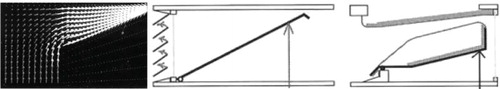
The lowest pressure differences within such a system are possible with an inlet shape for a venturi flow. By using that form it is already possible to produce an airflow that clings to the ceiling (>1 m) at a pressure difference below 3 Pa. Moreover, the same venturi flow that is used for daytime ventilation could be modified for use in night-time purging of heat from the mass of a building. In this way the amount of façade-elements such as windows or grilles for passive buildings can be reduced ().
Figure 2. CFD-simulation of airflow in a venturi-shaped inlet (left) and two types of similar air inlets (right) that have been tested in a climate chamber. In the right model sound-absorbing materials are added. However, a venture-shape in itself is not favourable for sound-isolation. A protecting element at the outside (like simulated in the CFD-calculation) could improve this. This way of protection does not have an effect on the air resistance.
The required comfort level can also be sub-optimally realized with air inlets that are already available within the Dutch building industry and if used as such the most influential design attribute of the system is the actual size and position of the inlet within the room. Minor additions and adaptations to proprietary systems are necessary in order to place the inlet at the right location ((c)) or to preheat the air with inserted simple heating pipes (). A disadvantage of the common solutions is that the total pressure difference over commonly available inlets is rather high (>5 Pa) due to the non-optimization of the system integration into the building.
The maximum velocity via an opening in a venturi can be calculated with the following equation:
(3)
which can also be derived from Bernouilli’s law.
3.3. Origin of the DR approach
One of the first studies on the effect of airflows on human sensation responses was a laboratory study in the mid-1980s where 100 subjects were exposed to a turbulent airflow (Fanger and Christensen Citation1986). The study was performed in a laboratory space, which had one outside wall and no windows. The airflow was coming from behind and aimed at the position of the seated subjects. The subjects participated in three-, two- and a half-hour experiments and the supplied air velocities fluctuated in a random manner. The turbulent airflow was characterized by the mean velocity and the turbulence intensity, defined by the standard deviation divided by the mean velocity. shows the found relationships between the mean air velocity, air temperature and the percentage of dissatisfied at a turbulence intensity of 34.6%.
Figure 3. The draught chart. The chart applies to sedentary persons, wearing normal indoor clothing, exposed to air velocity in the occupied zone of ventilated spaces. The turbulence intensity is 34.6% (Fanger and Christensen Citation1986).
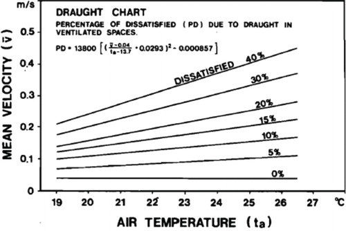
It appeared that people are more sensitive to draught from a turbulent air flow, coming from a mechanical ventilation system, then from a laminar flow. The back of the head was the most draught-sensitive part of the body. No significant differences between the draught sensitivity of men and women were found. Also it was found that there were substantial inter-individual differences in draught sensitivity.
In a later study the impact of turbulence intensity on the sensation of draught was investigated with more levels of turbulence (Fanger et al. Citation1988). Fifty subjects were exposed to air flow with low (Tu < 12%), medium (20% < Tu < 35%) and high (Tu > 55%) turbulence intensity and to six mean air velocities between 0.05 and 0.40 m/s. The sensation of draught was significantly influenced by the turbulence intensity. A model was presented which predicts the percentage of people dissatisfied due to the perception of draught as a function of air temperature, mean velocity and turbulence intensity (). The time constant of the velocity measurement equipment was 0.1 s; so fluctuations up to 10 Hz could be measured.
Figure 4. The draught risk model. The surfaces shown correspond to 10%, 15% and 20% dissatisfied, respectively. The axes represent turbulence intensity, mean air velocity and air temperature (Fanger et al. Citation1988).
These laboratory studies form the basis of the DR equation of the international standard EN-ISO-7730. The aim of this standard is to provide a calculation method of the allowed values of the combination of air temperature, air velocity and turbulence intensity. Given the nature of the laboratory studies, where airflows were generated mechanically, this equation to determine thermal comfort due to allowable air velocities cannot be considered valid for airflows with a natural characteristic, like airflows through windows and grids. Because turbulence in air flows through façade inlets can be very different, it is better to check, not only the turbulence intensity, but also the effect of the PSD on comfort (see Section 3.5).
3.4. Air flows and the human skin
Wind or airflows can be characterized in terms of time and space. Temporarily fluctuations can be hourly, diurnal or seasonal. Spatially, wind can be characterized by two horizontal vectors, the azimuth and a vertical vector, the elevation. Air does not flow exactly horizontally; the elevations varies with speed. In the laboratory studies of Fanger and Christensen the airflows were coming from behind the subjects; however recent studies show that people are more sensitive of airflows coming from the front (Simone and Olesen Citation2013). Conclusions from experiments carried out in controlled environments should be treated carefully because human perceptions might not be similar to the field observations (Djamila, Ming, and Kumaresan Citation2014). Various studies (e.g. Humphreys, Nicol, and Roaf Citation2016) show that people adapt themselves to the environment and control the environment to suit their comfort preferences depending on the physical and social context. What might be considered an unpleasant draught in one situation may be a welcome breeze in another.
When we perceive a warm or cool environment, we do not actually sense the temperature of the air or heaters directly, but rather we notify a change in conditions by our nerve endings, the thermoreceptors, which send signals in certain frequencies to the hypothalamus in the brain (Zhang Citation2003). The combined effect of air temperature and air movement on the human skin reaches the brain coded as frequency of nerve signals. Research shows that the frequency of change in airflows of between 0.2 and 1.0 Hz had a strong cooling effect on subjects (Huang, Ouyang, and Zhu Citation2012). Fluctuations with frequency between 0.3 and 0.5 Hz seem to have the greatest impact and are most likely to be perceived as draught (Madsen Citation1984). Higher frequencies (between 0.7 and 1.0 Hz) could also significantly affect thermal comfort (Ouyang Citation2006). Humans sense air temperature and air movement differently in cold and hot environments because the skin includes more cold than warm receptors (de Dear Citation2010).
3.5. Power spectral density
As turbulence intensity describes turbulence as a function of time, turbulence can also be studied in the frequency domain. PSD shows how power is distributed over a range of frequencies. The velocity, measured by time, can be transformed by Fourier transform into a PSD graph. In an example of the PSD is given. The PSD E(f) is defined as follows (Ouyang Citation2006):
(4)
To be able to quantify the power spectral characteristics of airflow, the so-called β-value can be used, which represents the negative slope of the logarithmic power spectrum graph. The higher the value, the higher the power in the low frequencies, which represents large period eddies (Ouyang Citation2006). gives examples of β-values of natural and mechanical airflows (Kang, Song, and Shiavon Citation2013).
Figure 5. PSD (Djamila, Ming, and Kumaresan Citation2014). On the vertical axis the power spectrum density E(f) is presented. The sampling interval is 0.13 s.
Figure 6. Representation of power distribution and β-value for natural (left) and mechanical airflow (right). The sampling interval is 0.1 s. The hot-wire anemometer could measure fluctuations up to 5 Hz (Kang, Song, and Shiavon Citation2013).
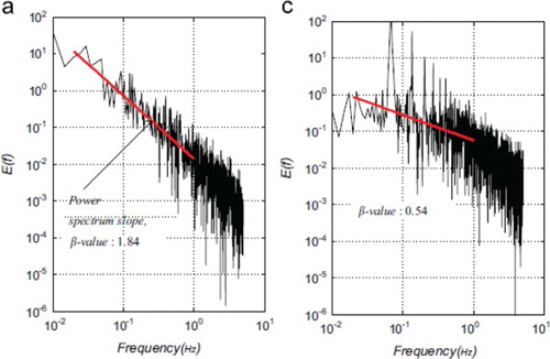
When we take a closer look at the difference in spectrum characteristics between natural and mechanical airflows, we see that natural airflows have higher β-value than mechanical ones.
When the airflow velocity is reduced, an increase in β-value of mechanical airflows is noticed. This is also seen to a lesser extent for natural airflows, although the β-value remains higher than 1.1 (Ouyang Citation2006).
Concerning human perception, it was found that airflows with higher β-values are perceived as more pleasant. The optimum range for β-values is between 1.41 and 1.80 and are mainly found in natural airflows (Kang, Song, and Shiavon Citation2013). This supports the findings that people prefer airflows from systems with the characteristics of those found with natural ventilation.
Much of the research on air velocities and advanced data-processing and analyses techniques is dependent in part on the sensitivity of the measuring devices. New research should clearly specify the required response time of the devices used, including conventional anemometers or modern ultrasonic measurement equipment. In order to develop more insight in the complete spectrum of PSD, high sensitive measurement equipment is recommended, but it is not clear yet how much effect high frequencies have. For many years it is already possible to measure fluctuations up to 100 Hz (Mayer Citation1987; van den Engel Citation1995a).
3.6. Still or variable?
The current air velocity standards seem to apply to situations with mechanical ventilation under (mainly winter) circumstances where they could cause draught complaints, but in situations with natural ventilation, higher temperatures and/or personal control opportunities other airflow characteristics might be preferred.
In warmer climates or under summer conditions draught might not be the main concern, but sufficient air movement is a significant advantage (Aynsley Citation2012). In naturally ventilated environments, airflows play an important role in controlling indoor air quality and thermal comfort. In extensive field studies (Arens et al. Citation2009; Hoyt, Zhang, and Arens Citation2009) it is found that people who feel cool prefer less air movement and those who feel warm prefer more air movement, even though the occupants did not have much control over air movement. For people voting for thermal sensation values of 0.7–1.5, the air movement limit can be extended to 0.8 m/s. Standards such as EN-ISO-7730 were based on the concept of avoiding any disturbing or undesirable air movement (draught). More recent standards, such as ASHRAE 2010 and EN-NEN-15251, appreciate that higher air speeds are useful in offsetting increased temperatures and allow higher airspeeds to maintain both the same total heat transfer from the skin and to promote thermal comfort. Another additional effect of air movement, especially around the face, is an increase of perceived air quality, even though the measured air quality was the same (Zhang et al. Citation2010). This could have important consequences for saving energy through the use of elevated air motion by means of personal control systems, operable windows and (advanced ceiling) fans (Huang et al. Citation2013).
The concept of ‘alliesthesia’ is another way of assessing air velocities and this knowledge can be used for designing naturally ventilated environments. When a certain environmental stimulus is able to restore the internal state of the body to its set-point, this is perceived as pleasant, this can be called positive alliesthesia. A stimulus that enlarges the discrepancy between the internal state and its set-point will be perceived as unpleasant: negative alliesthesia (de Dear Citation2010). Examples of negative alliesthesia are heating sources in a warm environment and temperature gradients that cause ‘warm head’ and ‘cold feet’. Positive alliesthesia can be a fire place in a cold room and ‘cool head’ and ‘warm feet’. A slight breeze can bring thermal pleasure when the core temperature is slightly above neutral, but the same air movement can be perceived as an unwanted ‘draught’ if the core temperature is below its set-point.
It seems that in steady-state conditions, people can be comfortable, but to be very comfortable, the environment should rather offer sensational transience, asymmetries and personal control (Arens et al. Citation2010; de Dear Citation2010; Brager, Zhang, and Arens Citation2015). In terms of design this asks, for instance, for new ideas on window design, the use of shadings, operable windows and ventilation grids in relation to summer and winter conditions.
4. Applications
The results of four different categories of functions are discussed in which decentralized natural air supply is a realistic option: offices, schools, hospitals and houses.
For a school (Regionaal Opleidingencentrum (regional educational centre [ROC] of Twente)) and a hospital, detailed climate chamber measurements have been carried out. Another school (De Schakel in Utrecht) has been measured just before being in use (Versteeg Citation2014). All the measurements are related to or based on the comfort-criteria of the EN-ISO 7730.
The office (Amolf Research Centre in Amsterdam), schools and houses are also built; so there is user experience as well. Up to now this is positive; however, no systematic user evaluation has been carried out yet.
All the presented systems have natural air supply and ME.
4.1. Offices
One of the requirements of clients can be as much natural ventilation as possible, as was the case for the occupants of the three storey Amolf ((a)). Here an induced natural supply system in the façade was combined with operable windows, a concrete core activation (CCA) system and a convector placed at floor level underneath the air inlet. Moreover, an outside sunshade was added. The pressure difference via the façade is lower than 10 Pa. Each room has a separate ME. Up to now, no draught problems of the occupants have been reported.
Figure 7. (a) Top figure: overview of the façade with outside sunshade. (b) Result of a CFD-simulation on an exceptional very cold winter day. The window is 13°C. There is a convector (540 W) underneath the air supply. Floor (24°C) and ceiling (30°C) are heated as well (CCA). The presented air velocities are between 0.25 and 1.93 m/s (dark area near the ceiling). However, CFD tends to overestimate the throw of the jet with small air flows (van den Engel Citation1995a). In the occupancy zone the air velocities are lower than 0.25 m/s. The supplied air temperature is −10°C (far below zero). 70 m3/h is supplied via an inlet with a height of 7 mm and width of 2 m (Ar = 0.0036). (c) An architectural detail of the natural air inlet-system for the Amolf Research Centre Architect: Dick van Gameren. The inlet is hidden behind a concrete façade-element.
4.2. Schools
An inducing natural air supply can be a low energy option for the successful ventilation of classrooms compared with more electricity hungry mechanically driven, ducted ventilation systems with heat recovery (MVHR). This is largely due to the fact that classrooms often have a high occupancy level and consequently a high internal heat load. Not only does the induced natural ventilation provide fresh air at a far lower mechanical energy cost, but the use of the body heat to warm the air passing through the class room and into the rest of the building will also limit the necessary amount of heating required for comfort in the school as a whole. On top of that, such systems offer much free cooling potential.
The starting point of the design should be provision of natural fresh air with draught prevention resulting from effective flow control. With heated pipes (), air can be warmed up to above 0°C to produce a DR lower than 20% (Cauberg-Huygen Citation2005). A combination is possible of induced natural ventilation with radiators below the inlet or CCA. For large schools with CCA built over several storeys, it is essential that the system is automatically closed off at the end of the occupancy period. This is necessary in order to reduce energy loss and to keep the temperature of the CCA as low as possible and to prevent a too large temperature difference between class rooms.
For schools a Dutch guide has been developed to improve the climatic conditions (ISSO Citation2008). In this publication, mechanical ventilation systems are compared with systems with natural air supply. In order to prevent draught, principles of induced air near the ceiling are presented. This Dutch guide has been a source of both information and inspiration for architects and consultants as to how to improve the quality of natural air supply while preventing down draughts and minimizing energy consumption.
A comparable, but more compact, system with only one heated pipe in the inlet and a radiator against the façade has been applied for the school De Schakel (Versteeg Citation2014). CFD-simulations and thermal comfort measurements according to EN-ISO 7730 in this other school confirmed the earlier conclusion that the DRs with this ventilation system are low and below 20%.
4.3. Hospitals
Hospitals are special environments with vulnerable occupants who may suffer from ventilation-related health problems. Natural air supply is an interesting alternative for mechanical supply, as there might be smaller risk of contamination by pathogenic micro-organisms than can be found in the air supplied by handling units and supply ducts with filters that are regularly, or irregularly, maintained and changed (Green Citation2011).
To achieve very low DRs, air should be preheated by more than 0°C, depending on outdoor conditions. Measurements of patient rooms for a new hospital indicate that DRs below 15% are possible with Archimedes numbers lower than 0.0003 (10 mm inlet size, 15°C, 2.6 m/s, 26 dm3/s m or 10°C, 3.6 m/s, 36 dm3/s m). These inlet temperatures are comparable with those produced by mechanical air supply systems (Peutz Citation2008). In this case, two air inlets with a width of 0.84 m are used. The limitations of the width of the air inlet, and the channelling of the flow from outside to inside (screens inside the plenum) also led to DR reductions ().
Figure 8. Air inlet-system of the ROC of Twente. Air inlets are placed in the façade, air is preheated with pipes and supplied to the room via a narrow slit near the ceiling.
Figure 9. Air inlet-system for a hospital in a mocked-up experimental room.
4.4. Houses
Disappointing monitored results from houses with MVHR in the Netherlands led to a growing interest in induced natural air supply systems via the façade. After health problems in the district Vathorst of the city of Amersfoort in 2007, MVHR seemed to be the main cause. However, this was mainly due to the poor installation of the MVHR system and lack of operable windows. Nevertheless, additional research initiated by the Ministry of Health made clear that the appreciation of natural air supply systems by occupants is still higher than MVHR (RIVM Citation2011).
Natural air supply with ME and full MVHR systems are all being continuously improved and both have a future, despite some recent adverse press on the subject. The choice of an optimal system often depends on the outdoor and architectural contexts, including conditions of ambient noise, pollution and the height of the spaces above ground. Often reported or recorded ventilation complaints are noise from the fans from ME and MVHR systems (van Dijken and Boerstra Citation2011) and high measured levels of CO2 in the sleeping rooms. The reported problems could be solved, for instance, by lower air velocities in the ventilation system (reduction of noise), local CO2-controlled valves or more conscious usage of the opening of the vents (reducing CO2-level). However, CO2 is not a good indicator of perceived air quality (Sassi Citation2016). There is no evidence to suggest yet that a technically more advanced system, such as a CO2-controlled system, leads to more occupant satisfaction or a more robust system. Moreover, occupant complaints or user satisfaction are not always directly related to physically measurable parameters. Probably not all dominant physical parameters are known, and psychological parameters, such as experience and expectation, may have a great impact as well.
More than half of the houses in the Netherlands are equipped with natural supply systems. For a passive or zero energy house, MVHR recovery used to be the standard for the past decade or so.
With an effective control of fresh air supply via the façade, natural supply with ME is now an option as well. An inlet with an air flow lower than 10 l/s/m, located more than 1.80 m above the floor, will not produce a serious draught problem. The higher the location above the floor, the lower the draught risk. For houses the average pressure difference is much lower due to a small required air flow per metre façade: around 1–2 Pa. An example of an air inlet near the ceiling of a (near) zero energy house is the Brabant House air inlet-system of Renz Pijnenborgh (Buma Citation2014 and ). This solution was developed by the architect because there is no radiator or convector underneath the air inlet, which increases draught risk. The house is heated by internal ‘warm walls’.
Figure 10. Example of air supply near the ceiling with the option of a curtain-location that will not disturb the air flow that enters the room (Renz Pijnenborgh).
5. Conclusions
In order to optimize occupant comfort and save energy, induced natural ventilation (air supply via the façade and exhaust via shafts) is a challenging option. One of the most practical solutions for the prevention of discomfort in dwellings or spaces with low occupancy is to ensure that an amount of air can be supplied via the façade of around 10 l/s m, from outlets below the ceiling. With this limited amount of fresh air supply, mixing of cold and warm surrounding air is possible within a zone of circa 1 m from the façade. When larger airflows are required, such as in classrooms, the pressure differences should be increased, in order to prevent draughts and to direct and maintain the air flow as close to the ceiling possible. Induced natural ventilation works well in a hybrid combination with a ME system that can guarantee the required pressure difference (5–10 Pa) and direction of flow. In that case it is possible to realize sufficient air supply and an air flow that clings to the ceiling.
For inducing vents for an outer wall, a wide range of natural air supply systems, principles and products are available for use in carefully designed systems to reduce draught risk and energy used for ventilation. A further development of these systems can involve the simplification of the shape of these vents in order to reduce the pressure loss below 5 Pa and make them more appropriate for night ventilation.
Induced natural air supply is also an option when the outdoor temperature rises and night ventilation alone is not enough to fulfil the comfort requirements. In that case a combination of the system with cooled floors and/or ceilings is possible (Figures and ).
Induced natural air supply systems are often used in conjunction with operable windows for summer-time comfort cooling as well. More insight into the physical principles of air flows, and turbulence, is necessary to reinforce the current trend in induced natural ventilation systems becoming a more commonly specified solution.
Points to watch out for in the design of such systems are the prevention of return air flows and the reduction of resistance of incoming air across the external wall. Heat losses via the air inlet should be limited as much as possible through the use of good detailing to eliminate cold bridging in the systems in their passage through the external envelope of the building.
To assess the effectiveness of induced natural air supply systems, it is necessary to also evaluate their performance using real occupants in their ordinary work or living spaces in order to give more insight into the actual comfort conditions they create.
The measurement of the PSD in summer and winter, combined with occupant feedback, will give more detailed insight in the thermal quality of air flows across the systems.
Evaluations of the energy consumption of natural air supply systems in use are also necessary to gauge the real-world cost benefits of their adoption in real buildings.
Disclosure statement
No potential conflict of interest was reported by the authors.
Additional information
Notes on contributors
Peter J. W. van den Engel
Peter J.W. van den Engel educated as an architect, is since 1987 specialized on the design of hybrid ventilation systems and air flow simulations. Currently he is a consultant/air flow specialist at Deerns consulting engineers and teacher/researcher at Delft University of Technology, Faculty of Architecture, Chair Building Services. His main field of interest is making buildings healthier and energy-efficient by using natural energy-flows, with better understanding of human behaviour.
Stanley R. Kurvers
Stanley R. Kurvers is working in the field of indoor environmental quality since 1979, first as a researcher for the Dutch Occupational Health Service and later for consultancy companies. His main interests are thermal comfort, indoor air quality and post occupancy evaluation. Currently he is a researcher at the Faculty of Architecture, Delft University of Technology, and Chair of Indoor Environment where he contributed to the development of tools, guidelines and methods for building indoor environmental quality.
References
- Arens, E., M. A. Humphreys, R. de Dear, and H. Zhang. 2010. “Are ‘Class A’ Temperature Requirements Realistic or Desirable?” Building and Environment 45: 4–10.
- Arens, E. A., S. Turner, H. Zang, and G. Paliaga. 2009. “Moving Air for Comfort.” ASHRAE Journal 51 (5): 18–21.
- Aynsley, R. 2012. “How Much Do You Need to Know to Effectively Utilise Large Ceiling Fans?” Architectural Science Review 55 (2): 16–25.
- Bluyssen, P. M. 2009. The Indoor Environment Handbook – How to Make Buildings Healthy and Comfortable. London: Taylor & Francis.
- Brager, G., H. Zhang, and E. Arens. 2015. “Evolving Opportunities for Providing Thermal Comfort.” Building Research & Information 43 (3): 274–287.
- Buma, W. 2014. “De Brabantwoning.” TVVL-magazine 2014 (4): 34–36.
- Cauberg-Huygen. 2005. ROC van Twente te Hengelo. Klimaatkameronderzoek. Report 2004.2297-1v2.
- de Dear, R. 2010. “Thermal Comfort in Natural Ventilation – A Neurophysiological Hypothesis.” Proceedings of conference: adapting to change: new thinking on comfort cumberland lodge, Windsor, April 9–11, 2010. London: Network for Comfort and Energy Use in Buildings.
- van Dijken, F. A., and A. C. Boerstra. 2011. “Onderzoek naar de kwaliteit van ventilatiesystemen in nieuwbouweengezinswoningen.”
- Djamila, H., C. C. Ming, and S. Kumaresan. 2014. “Exploring the Dynamic Aspect of Natural Air Flow on Occupants Thermal Perception and Comfort.” Proceedings of 8th Windsor conference: Counting the cost of comfort in a changing world cumberland lodge, Windsor, April 10–13, 2014. London: Network for Comfort and Energy Use in Buildings.
- van den Engel, P. J. W. 1995a. “Inducing Vents and Their Effect on Air Flow Patterns, Thermal Comfort and Air Quality.” Indoor Air, an Integrated Approach, 1994. Gold Coast, Australia: Elsevier Science.
- van den Engel, P. J. W. 1995b. “Thermisch Comfort en Ventilatie-Efficiency Doort Inducerende Ventilatie via de Gevel.” Thesis, TU-Delft.
- van den Engel, P. J. W. 2005. “Healty Climate in Schools Due to Ventilation an Slab Heating.” Proceedings of Clima 2005, Lausanne.
- van den Engel, P. J. W. 2007. “Typologies of Hybrid Ventilation in Schools.” Proceedings of Clima 2007, Helsinki.
- Fanger, P. O., and N. K. Christensen. 1986. “Perception of Draught in Ventilated Spaces.” Ergonomics 29 (2): 215–235.
- Fanger, P. O., A. K. Melikov, H. Hanzawa, and J. Ring. 1988. “Air Turbulence and Sensation of Draught.” Energy and Buildings 12 (1): 21–39.
- Green, J. 2011. http://www.ted.com/talks/jessica_green_are_we_filtering_the_wrong_microbes.html.
- Heiselberg, P., A. van der Aa, S. Aggerholm, Å. Blomsterberg, M. Citterio, W. de Gids, Y. Li, et al. 2002. “Principles of Hybrid Ventilation.” Summary of IEA-ECBCS Annex 35 “hybrid ventilation in new and retrofitted office buildings,” Aalborg University.
- Hoyt, T., H. Zhang, and E. Arens. 2009. “Draft or Breeze? Preferences for Air Movement in Office Buildings and Schools from the ASHRAE Database.” Proceedings of healthy buildings, Syracuse, NY, September 13–17.
- Huang, L., Q. Ouyang, and Y. Zhu. 2012. “Perceptible Airflow Fluctuation Frequency and Human Thermal Response.” Building and Environment 54: 14–19.
- Huang, L., Q. Ouyang, Y. Zhu, and L. Jiang. 2013. “A Study about the Demand for Air Movement in Warm Environment.” Building and Environment 61: 27–33.
- Humphreys, M., F. Nicol, and S. Roaf. 2016. Adaptive Thermal Comfort. Foundations and Analysis. London: Routledge.
- ISSO. ISSO-publicatie 89. 2008. “Binnenklimaat scholen.”
- Kandzia, C., and M. Schmidt. 2010. “Bauer Entzaubert? Untersuchung zu instationären Betriebsweiseneines Luftfürungssystem.” RWTH-research, Technik 13.
- Kang, K., D. Song, and S. Shiavon. 2013. “Correlations in Thermal Comfort and Natural Wind.” Journal of Thermal Biology 38: 419–426.
- Leenaerts, C. L. M., and P. Briggen. 2014. “Innovatief ventilatieconcept voor ‘frisse school’ MFA het nest. Ventilatieconcept met natuurlijke toevoer voorkomt klachten binnenklimaat.” Bouwfysica 3: 2–6.
- Madsen, T. L. 1984. “Why Low Air Velocities May Cause Thermal Discomfort.” Proceedings of indoor air, Stockholm.
- Mayer, E. 1987. “Draught Measurements in Ventilated and Non-ventilated Buildings.” Proceedings of the 8th AIVC-conference, Űberlingen.
- Ouyang, Q. 2006. “Study on Dynamic Characteristics of Natural and Mechanical Wind in Built Environment Using Spectral Analysis.” Building and Environment 41: 418–426.
- Peutz. 2008. “Eindrapportage Klimaatkameronderzoek Reinier de Graaf.” Report BZ 469-4.
- Ragas, A. M. J., R. Oldenkamp, N. L. Preeker, J. Wernicke, and U. Schlinck. 2011. “Cumulative Risk Assessment of Chemical Exposures in Urban Environments.” Environment International 37: 872–881.
- RIVM. 2011. “Kwaliteit van mechanische ventilatiesystemen in nieuwbouw eengezinswoningen en bewonersklachten.” Report 630789006.
- Sassi, P. 2016. “Evaluation of Indoor Environment in Super-insulated Naturally Ventilated Housing in the South of the United Kingdom.” Proceedings of the 9th Windsor conference, Windsor.
- Schuur, A. 1996. “Ventilatie, geluidsbelasting en gevelontwerp.” Ventilatie via de gevel, een delicate balans tussen luchtkwaliteit en energiegebruik. Symposiumbook DUT.
- Simone, A., and B. W. Olesen. 2013. “Preferred Air Velocity on Local Cooling Effect of Desk Fans in Warm Environment.” Proceedings of 3th AIVC–4th TightVent–2nd venticool joint conference, Athens, September 25–26.
- Versteeg, H. 2014. “Natuurlijke Toevoer van Ventilatielucht in Onderwijsruimten.” TVVL-Magazine 2014 (4): 2–4.
- Zhang, H. 2003. “Human thermal sensation and comfort in transient and non-uniform thermal environment.” Thesis, UC Berkeley.
- Zhang, H., E. A. Arens, D. Kim, E. Buchberger, F. S. Bauman, and C. Huizenga. 2010. “Comfort, Perceived Air Quality, and Work Performance in a Low-power Task-ambient Conditioning System.” Building and Environment 45 (1): 29–39.