
Abstract
The Dougong (brackets set) is a traditional Chinese capital used to transfer the roof load to the columns. Besides its historical significance, it is also known for its anti-seismic and environmentally friendly properties. This paper investigates which existing digital design and fabrication technologies are suitable for the automated assembly and production of the Dougong joint by reviewing relevant research. The paper systematically reviews and comparatively analyses 23 articles filtered through 1,774 publications searched by using the keywords ‘timber’, ‘digital fabrication’, and ‘robot’ in the databases Scopus, CumlnCAD, ScienceDirect, Engineer Village, IEEE and Semantic Scholar. Our findings include a comparative analysis chart evaluating workflows, tools and technologies on their suitability for the robotic reinterpretation of the Dougong, as well as the proposal of a novel design for fabrication workflow for that particular purpose, which is verified through the design and fabrication of a timber column fragment.
1. Introduction
The Dougong is an independent class of joints within the traditional Chinese timber structural systems. It comprises various Gong and Dou elements, arch-form and square-form components, respectively (Liang Citation2006). Incorporating the Dougong in contemporary design has three benefits: seismic stability, sustainability, and cultural significance. Long et al. (Citation2020) conducted experiments proving that the Dougong has remarkable energy absorption properties (anti-seismic properties). The pine wood utilized to build the Dougong is a natural material that can regrow, which is more sustainable compared to steel and concrete. Moreover, integrating the Dougong into contemporary Chinese design also pays tribute to the Chinese cultural heritage. Due to its complex production technology, specialized carpenters are often required to build the Dougong on construction sites of timber-frame buildings (Ma Citation2003).
Over thirty Dougong types are described in the historic rulebook Gongcheng Zuofa Zeli (Liang Citation2006), but their classification can be simplified according to the position within buildings. Overall, the Dougong can be categorized into three types (Figure ): the intermediate set, the corner set and the column set (Ma Citation2003). Generally, the Dougong's function is to translate loads of the roof to foundations through pillars and enhance the seismic performance of the timber-frame system. Conventionally, it is produced manually, which is a time-demanding process. It comprises five elements (Figure ), including the Gong, Qiao, Ang, Dou and Shen (Liang Citation2006). According to the Technical Code for Maintenance and Strengthening of Ancient Timber Buildings published by China Architecture & Building Press (MHURD Citation1992), the tolerance gap between two Dougong components should not exceed 1 mm. The tolerance gap between the tenon and mortise of the two components is set as 1 mm in our research.
Our research focuses on reinterpreting the Dougong in contemporary architecture by using parametric tools and robotic fabrication techniques. We aim to develop a framework integrating design, structural optimization, automated production, and robotic assembly. Therefore, a systematic review of related research is necessary to identify and evaluate research methods, tools, and techniques that may contribute to our approach. Consequently, this paper will answer the following questions:
What is the current status of research about the utilization of digital technologies on the Dougong and its related structures?
Which of the examined techniques would be more suitable for the reinvention and use of the Duogong joint in contemporary timber-frame architecture?
How can we develop a design-to-fabrication for the digital reinterpretation of the Dougong joint?
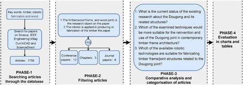
Our findings add new insights to the body of knowledge by identifying and categorizing existing robotic technologies that have been applied in the digital fabrication of the Dougong and its related beam and joint primary elements. Our systematic review is undertaken in five distinct phases (Figure ): 1) searching articles through databases, 2) filtering selected articles 3) the comparative analysis and categorization of articles, 4) evaluation in charts and tables, and 5) proposing a workflow for reinterpreting the Dougong and testing the novel workflow on a prototype.
Figure 1. Positions of Dougong in historical Chinese buildings.
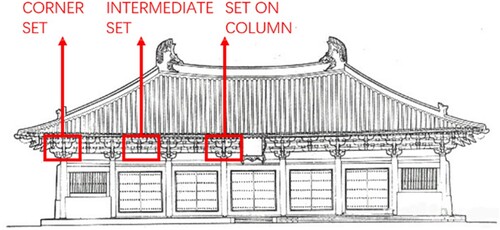
Figure 2. Dougong components and structure.
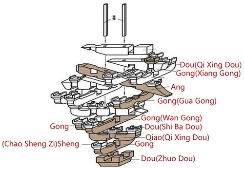
Figure 3. Flowchart of the systematic review method.
2. Methodology
As shown in Figure , this paper screened, methodically reviewed and comparatively investigated existing papers through four distinct phases. Databases included Scopus (Elsevier's abstract and citation database), IEEE (Institute of Electrical and Electronics Engineers), Engineer Village, CumlnCAD (Cumulative Index about publications in Computer Aided Architectural Design), ScienceDirect and Semantic Scholar. Keywords (timber, digital fabrication and robotic fabrication) were applied for searching in titles, abstracts, and keywords of publications in the databases. The criteria for choosing these databases were accuracy, liability and comprehensiveness. The database CumlnCAD was supported by the sibling associations ACADIA, CAADRIA, eCAADe, SIGraDi, ASCAAD and CAAD futures, the leading digital architecture research conferences in the world. Therefore, CumlnCAD covered main conference paper searches, while Scopus and ScienceDirect contained journal papers and book chapters related to our topic. At the same time, expanding search in IEEE, Engineer Village and Semantic Scholar ensured to unignore any academic practice deriving from engineering-originated research.
Consequently, our search results revealed 1,774 academic publications, including 1,579 conference papers in CumlnCAD, 164 articles in ScienceDirect, 11 papers in Scopus and 20 publications in Semantic Scholar. No relevant papers were found in the IEEE and Engineering Village. The next step was to filter these publications based on relevance to our research topic.
In phase two, the selected articles were filtered, thus, repeating papers, review publications, and low-relevance articles were removed. The databases’ filter tools screened the papers first, removing 72 articles. Firstly, articles about news, encyclopaedias, short communications, and reviews were removed. Secondly, papers unrelated to architecture, such as decision science, chemical engineering, and mathematics, were removed. The remaining 1,702 articles were screened again by reading abstracts, whereby non-timber-related joint or framework structures (e.g. shells, walls), were removed. Overall, 1,751 articles were removed, resulting in 23 articles published between 2013 and 2021.
In phase three, the remaining articles were categorized by analysing publication sources, publication year and locations of the first authors’ institutions. Furthermore, the papers were analysed according to design workflows, application types, optimization methods, robotic end-effector types, robotic firmware, and human-robot cooperation methods.
In phase four, the articles were evaluated in charts according to suitability for rethinking/reinventing the Dougong using robotic fabrication technologies. The evaluation revealed opportunities, challenges and limitations, which helped to develop a ‘file to fabrication’ framework for the upper-named purpose.
Finally, based on the findings of phase four, we proposed a file-to-fabrication framework suitable for Dougong’s reinterpretation thus it can be utilized in contemporary architecture and design projects. A pillar was applied to test the feasibility of the workflow.
3. Current status of the existing research related to Dougong structures
3.1. Distribution of articles according to the publication source
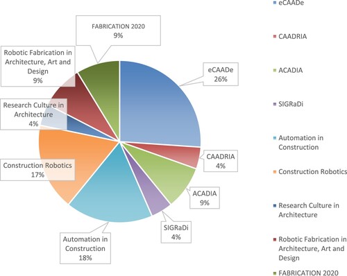
The article distribution overview based on publication sources can be seen in Figure . Dougong-related articles were published mainly in eCAADe (Education and Research in Computer-Aided Architectural Design in Europe), ACADIA (Association for Computer-Aided Design in Architecture), CADRIA (Computer-Aided Architectural Design Research in Asia) and SIGRaDi (Sociedad Iberoamericana de Gráfica Digital). Overall, 48% of the papers (10 out of 23) appeared in the four conferences, eight papers were published in journals, and only 9% were published in books. However, only three papers referred to the Dougong, indicating the topic was a new area worth exploring. The other papers were selected due to their technologies and workflows, which could be helpful in our research.
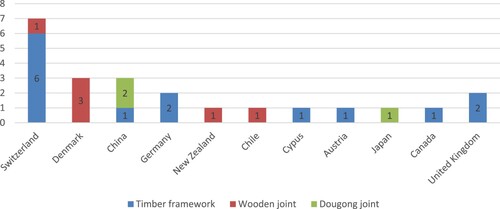
Figure 4. Distribution of articles by sources of publication (total number of articles: 23).
Overall, six articles had a first author from Switzerland, followed by Denmark and China (three articles), and Germany (two articles) followed by main authors from New Zealand, Chile, Cyprus, Austria, Japan and Canada (Figure ).
Figure 5. Geographical distribution of articles (total number of articles: 23).
3.2. Publication year
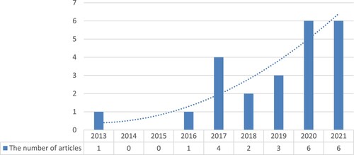
All selected papers were published between 2013 and 2021 (Figure ), with no publications related to the topic before 2013. We can see an upward trend in the number of articles published over the years, with one drop in 2018. In 2017, there was a sudden increase to four articles, while there were no articles at all from 2014 to 2015 and a steady increase from 2018 to 2021, with fifteen. The steady increasing trend indicated a growing interest in the research topic.
Figure 6. Chronological distribution of articles.
4. Analysis and categorisation
4.1. Application fields
The filtered articles were categorized into two categories: 1) contemporary timber structures and 2) traditional timber structures (Table ). Fourteen articles fell within the category of contemporary timber structures, followed by nine within traditional timber structures.
Table 1. Article categorization based on their timber structure type.
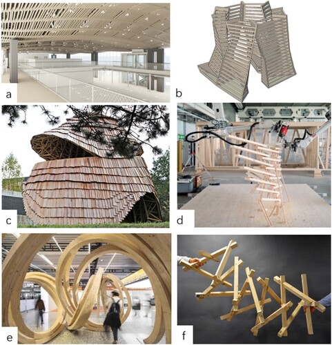
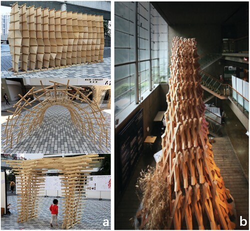
Four articles, categorized as contemporary timber structures, explored the design of standardized structural components produced automatically and built with high efficiencies, such as a timber bridge (Figure a) (Naboni and Kunic Citation2020 and Kunic et al. Citation2021) and a reversible connection joint (Figure b) (Kunic et al. Citation2021), and a non-standardized beam structure (Adel et al. Citation2018). Six articles applied robotics to fabricate freeform timber structures, such as a sizeable free-form timber roof (Figure a), a free-form wall (Figure b), a free-form double-storey structure (Figure c), an innovative dowel-laminated timber structure (Figure d), a double-curved glulam-beam structure (Figure e) and douglas fir struts. These above elements were designed without a complex curve to an easy position by robotic arms and mass production. These projects could be described as timber structures made of standardized components, characterized by the flexibility and feasibility of workflows integrating parametric design and robotics.
Figure 7. a) Timber arch bridge(Kunic et al. Citation2021); b) A re-configurable timber architecture (Kunic et al. Citation2021).
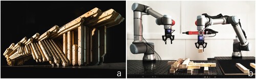
Figure 8. Six free-form timber structures, a) sizeable freeform roof (Willmann et al. Citation2016), b) free-form timber walls (Kontovourkis Citation2017), c) double-storey structure(Eversmann, Gramazio, and Kohler Citation2017), d) free-form structure designed with dowel-laminated timber(Leopold, Robeller, and Weber Citation2019), e) freeform timber structure with double-curved glulam beams (Chai, So, and Yuan Citation2021), f) douglas fir struts (Morse et al. Citation2020).
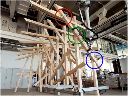
Apolinarska et al. (Citation2021) utilized machine learning, an artificial intelligence algorithm, to teach a robotic arm to assemble a double lap joint (Figure ). Apolinarska et al. (Citation2021) utilized robotic clamp end-effectors to assemble a freeform timber structure with varied beams (Figure ). The two papers mainly explored robotic fabrication, without incorporating design and structural optimization.
Figure 9. A robot trained to fabricate an overlap joint by Apolinarska et al. (Citation2021).
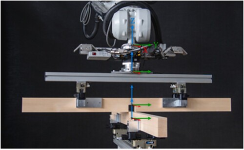
Figure 10. Free-form timber structure by Apolinarska et al. (Citation2021).
In the category of traditional timber structures, Mostafavi et al. (Citation2020) and Xian, Hoban, and Peters (Citation2020) explored the robotic fabrication of reciprocal structures, such as a freeform frame structure (Figure ) and a timber wall (Figure ). However, Xian and Peters utilized screws as primary connections in the timber wall.
Figure 11. A freeform, reciprocal timber frame structure (Mostafavi et al. Citation2020).
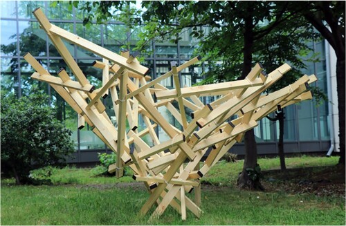
Figure 12. A timber-frame wall(Xian, Hoban, and Peters Citation2020).

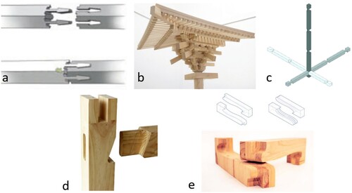
Two articles designed new structures based on rethinking the Dougong in contemporary design, such as traditional interlocking joints including the Dougong (Figure a) (Lange Citation2017), and applying the Dougong in a timber tower (Figure b) (Chai et al. Citation2019). Their article only focused on connection methods between verified components of the Dougong rather than mechanical properties.
Figure 13. a) Three timber explorations designed according to the Dougong, a reciprocal structure, and a rigid lock system (Lange Citation2017); b) A timber tower designed based on the connection method of the Dougong (Chai et al. Citation2019).
Five articles explored reproducing elements of traditional structures with robotics. Three papers were about traditional Japanese joints, such as a traditional Japanese joint in a frame pavilion (Figure a) (Dank and Freissling Citation2013), a part of a traditional Japanese pagoda (Figure b) (Takabayashi and Kado Citation2019), the Japanese Chidori joint (Figure c) (Koerner-Al-Rawi et al. Citation2020), the traditional T-bridle joint (Figure d) (Böhme et al. Citation2017), the Mortised Rabbeted Oblique Splice joint (Figure e) (Heesterman and Sweet Citation2018). These articles also identified two research directions in dealing with traditional timber structures: the reproduction of historic structures and the reuse in contemporary design.
Figure 14. a) a Japanese wood joint (Dank and Freissling Citation2013), b) a part of a traditional Japanese pagoda(Takabayashi and Kado Citation2019), c) a Chidori joint (Koerner-Al-Rawi et al. Citation2020), d) a T-bridle joint, e) mortised rabbeted oblique splice(Heesterman and Sweet Citation2018).
In summary, the above papers show that simple geometry and standardized dimensions of the timber units are key requirements for automated production and assembly (Naboni and Kunic Citation2020), (Kunic et al. Citation2021). The widely applied fixation method of using screws would not be suitable for our research as the Dougong relies on a tenon-mortice connection.
4.1.1. Optimization methods
This section analyses and categorizes optimization methods in the selected articles. In Table , nine of twenty-one selected papers utilized three optimization methods: topology optimization (TO), multi-objective optimization (MOO) and genetic algorithm (GA). The TO applied to structural design is a computational method for concentrating the material distribution in those areas of the design space where structural stresses are prominent; it is applied within a given set of loads, boundary conditions and constraints. The MOO focuses on mathematical optimization problems involving the optimization of over one objective function, such as maximizing the stiffness of timber buildings while minimizing mass. The GA is a metaheuristic used to generate high-quality solutions based on a fitness function, such as minimizing or maximizing displacement of the timber structure. TO and MOO were applied widely through the Grasshopper plugins Millipede and Wallacei (Makki et al. Citation2018), while Karamba3D developed by Preisinger (Citation2013) was famous for mechanical analysis.
Table 2. Article categorization based on the optimization method used.
Naboni and Kunic (Citation2020), and Kunic et al. (Citation2021) included the TO Grasshopper plugin Millipede in designs. They presented the design and fabrication of a timber structure using the TO, voxelisation and robotics. The plugin was applied to optimize the material layout and generate stress lines where various wooden components were positioned.
Kontovourkis (Citation2017) developed a Grasshopper script to generate the shape of a timber pavilion. He optimized the design by maximizing space and minimizing volume by using MOO with the plugin Octopus. Mostafavi et al. (Citation2020) used the Grasshopper plugin Wallacei to find optimal configurations by minimizing the max structural displacement and elastic energy and maximizing the total average height of accessible space. Xian, Hoban, and Peters (Citation2020) used the Galapagos (a component in Grasshopper), to reduce the eccentricity of a timber wall.
Eversmann, Gramazio, and Kohler (Citation2017) optimized beams’ cross-sections by using section-optimization functions of Karamba3D, a finite element analysis plugin in Grasshopper. Chai et al. (Citation2019) designed a timber structure based on Dougong-inspired elements, whose length, layout and section were optimized with Karamba3D.
In summary, adopting TO in a design-to-fabrication workflow would increase its material efficiency. While GA optimization could resolve a single objective, such as eccentricity, MOO could optimize single and multiple objectives. Karmaba3D appears to be a useful tool because it could output values of displacement, mass, and stiffness.
4.2. Robotic tools and technologies
4.2.1. Robotic end-effectors
We have identified nine end-effectors in the selected articles: the gripper/clamp, the spindle, the camera, the electric screwdriver, the band saw, the circular saw, the square chisel, and the vibration chisel (Table ). Seventeen articles mainly explored single-function end-effectors. Eight of the seventeen articles applied robotic gripper effectors to position materials in the assembly and production.
Table 3. Article categorization based on robotic end-effectors used.
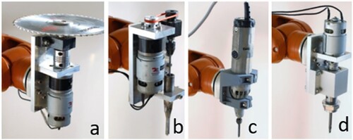
Chai, So, and Yuan (Citation2021) used an electric bandsaw to cut beams and a spindle to mill mortise and tenons (Figure ). Leopold, Robeller, and Weber (Citation2019) explored a workflow of a combined gripper and spindle end-effector, where an ABB robot with a gripper holding slats and another one with a spindle drilled holes in them. In Figure , a circular saw, a square chisel, and a vibration chisel end-effectors combined with a CNC router were introduced in four traditional carpentry tools to process the part of a traditional Japanese building (Takabayashi and Kado Citation2019).
Figure 15. a) a band saw end-effector, b) a spindle end-effector used to produce free-form beams (Chai, So, and Yuan Citation2021).
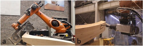
Figure 16. a) circular saw, b) square chisel, c) vibration chisel and d) router, designed by Takabayashi and Kado (Citation2019).
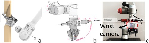
As seen in Figure a, a robotic multi-function end-effector with a mechanical clamp and a tool changer was designed for assembling a spatial frame structure (Apolinarska et al. Citation2021). Naboni and Kunic (Citation2020) applied two UR10e robots using gripper end-effectors and a CNC router to fabricate a wooden bridge. In addition, a recent article by Kunic et al. (Citation2021) improved work efficiency by introducing a multi-functional end-effector, including a gripper, a wrist switch and a screwdriver (Figure b). The gripper was used to assemble components into a bridge. A screwdriver was applied to fix it with w. The two functions could be switched manually with the wrist switch. Kunic et al. (Citation2021) added a wrist camera to scan beams to calculate the bolt-holes’ position, beside the gripper and the screwdriver (Figure c). The integrated robotic end-effector made the assembly straightforward and efficient, easy for architects to comprehend.
Figure 17. a) mechanical clamp and quick tool changer (Apolinarska et al. Citation2021), b) multi-functional end-effector, including a gripper, wrist switch and screwdriver(Kunic et al. Citation2021),c) end-effector with a wrist camera applied to scan beams (Kunic et al. Citation2021).
In summary, a circular saw, a square chisel, and a vibration chisel end-effectors are useful tools for milling timber components, however, their production efficiency appears to be lower than a CNC router. Using a gripper end-effector is suitable for the automated assembly because it could mimic a craftsman’s hand movements. Furthermore, a 3D scanning camera could calculate the tenon-mortise positions during robotic fabrication.
4.2.2. Robotic firmware
Table categorizes the filtered articles based on robotic firmware types. Twelve articles generated robotic toolpaths and simulated fabrications in Grasshopper, utilizing plug-ins such as KUKAprc, HAL, ABB and FURobot, which showed that the software was top-rated in the field. Eight more articles introduced Robotstudio, COMPAS FAB, PyBullet and CAM to create a robotic fabrication toolpath. According to the above papers, the most widely used software was Rhinoceros3D and its plugin Grasshopper since it integrated model generation, mechanical analysis, fabrication simulation and robotic toolpath generation. It was easy for architects without a previous engineering background to use for simulation and fabrication purposes.
Figure 18. Proposed workflow for reinterpreting the Dougong joint.
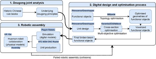
Table 4. Analysis of robotic firmware used in the selected papers.
4.2.3. Robotic fabrication and human-robot collaboration methods
In Table , six papers explored robotic production and manual assembly of timber-frame components. Lange (Citation2017) designed various robotic tools to produce wooden beams (Figure a). The beams held by bespoke tools were milled by a CNC router and then assembled manually. Dank and Freissling (Citation2013), Chai et al. (Citation2019), Mostafavi et al. (Citation2020), and Chai, So, and Yuan (Citation2021) used a KUKA robot with a milling end-effector to produce wooden beams assembled manually. Human-robot collaboration was applied to the fabrication phase, but not the assembly, which was conducted manually.
Table 5. Human-robot cooperation types.
Furthermore, Morse et al. (Citation2020) applied augmented reality (AR) for the assembly of timber elements. AR was utilized to control the robotic arm to assemble a small timber beam structure connected with lap joints, as shown in Figure e. However, the use of AR-assisted assembly increases the tolerances to 2 mm.
Ten articles explored auto-fabrication workflows, where timber components were produced robotically but assembled in human-robot collaboration. Adel et al. (Citation2018), and Xian, Hoban, and Peters (Citation2020) produced and assembled wooden beams automatically layer by layer into a structure. A craftsman used an electric drill to fix the beams with screws. Willmann et al. (Citation2016), and Eversmann, Gramazio, and Kohler (Citation2017) applied a similar method for a wooden pavilion and a timber roof. Due to the large size, they divided the structures into smaller parts. The parts were produced and assembled robotically but fixed together manually with screws.
Leopold, Robeller, and Weber (Citation2019) assembled a freeform timber tower with one robotic arm, drilled by another, and manually fixed with timber dowels. In the study by Naboni and Kunic (Citation2020) and Kunic et al. (Citation2021), two UR robots were utilized to assemble the various components produced with a CNC router. The assembly process took place layer-by-layer, following the stress lines of the bridge. Robots were responsible for the assembly and fixation tasks while switching from one task to the other took place manually. In a study by Kunic et al. (Citation2021), the one UR robot with the gripper assembled or unassembled the beams in the layer-by-layer method while the screwdriver screwed or unscrewed them based on the bolt holes positions detected by a camera.
Kontovourkis (Citation2017) fabricated parts of the timber pavilion using a method whereby a robotic arm would cut components at both ends and assemble them into a structure while the glueing would take place manually. Before the final assembly, the workflow was tested in a mock-up made of cheaper, foam-made components, thus any occurring issues were able to be corrected.
Only three papers explored reproducing traditional timber structures. Böhme et al. (Citation2017) reproduced a tenon-mortise of a historical building in Chile robotically and assembled it manually. They built a parametric model based on the joint's dimension measured in the National Maritime Museum of Chile. They analysed visual simulation results of robotic fabrication in Rhino/Grasshopper to avoid collisions. Heesterman and Sweet (Citation2018) produced robotically and assembled manually a traditional Japanese joint, whose geometry was adjusted for efficient production based on a feedback loop of productions. Takabayashi and Kado (Citation2019) applied the robotic arm to reproduce a corner, including the Dougong, of a traditional Japanese timber tower. The reproduced components were assembled manually. Their production method appears cumbersome and inefficient, so it could work in heritage conservation rather than mass-producing components.
Three papers were about the auto-assembly of timber structures. Apolinarska et al. (Citation2021) collected data from robotic simulation assemblies fed into an algorithm that trained the robot arm to assemble components of the lab joints accurately. However, this approach appears difficult for users without computer science backgrounds. Apolinarska et al. (Citation2021) described an assembly workflow for designing and fabricating a spatial timber structure using custom-built, remote-controlled, and high-force robotic clamps. The assembling sequences were determined based on the connection order between tenon and mortise. Koerner-Al-Rawi et al. (Citation2020) produced a timber frame with a CNC router. Then, to assemble a discrete unit, a robot with a bespoke gripper holed and another robot twisted a timber beam to interlock it with another beam. The assembly sequences of discrete units within a large-scale timber frame were established based on the connection order of timber joints. The research highlighted the geometric adjustment, such as tenon-mortise straight angle, to avoid collisions in fabrications, which could also be considered in our research. They also emphasized the importance of the assembly order of the tenon and mortise during robotic fabrication.
Regarding the robotic fabrication assembly, two papers (Claypool et al. Citation2020; Retsin et al. Citation2020) highlighted a computational design and fabrication method for timber assembly, based on the concept of discreteness. They attempted to transfer the core concepts of ‘digital materials’ to architectural modularity. In their research, various prefabricated and modular timber elements were designed to assemble functional buildings from smaller parts.
Kramberger et al. (Citation2022) introduced the Learning by Demonstration (LbD) concept in the robotic assembly of complex timber trusses. The trusses were designed in Rhinoceros/Grasshopper and fabricated using a CNC router. For its assembly, an experienced operator manually controlled a UR10e robot to assemble the tenon-and-mortise-based joints, using a bespoke gripper. All assembly data, such as rotation angles, the position of joints and the toolpath, were transferred to a bespoke ROS system. The code could be applied to repeat the fabrication process for mass manufacturing. The framework casts light on the assembly of complex timber structures with complex joinery in a layered fashion.
According to the analysis of the selected paper, the AR-assisted assembly and human-robot collaboration could be helpful in assembling complex timber structures, such as the Dougong. However, the AR-assistant assembly has a 2 mm tolerance, whereas the maximum tolerance gap for Dougong connection joints is 1 mm. Therefore, a further testing is necessary to identify the suitability of the AR-assisted robotic assembly for the Dougong. The design-to-fabrication concept of discretisation elements matches the Dougong assembly, a naturally discrete timber system based on its functions. A prototype test before mass assembly could identify the potential collisions.
5. Findings
5.1. Limitations and potential of digital design and optimization methods
The optimization and fabrication methods used in sixteen of the selected papers required the discretisation of their unit components. Discrete components have a limited number of connection points, following strict connection rules and can be prefabricated in the lab and assembled in situ into various structures such as pillars, walls, arches or towers. Standardization and prefabrication are Dougong's main properties, thus the reinvented Dougong components could act as discrete elements because they also have a limited set of connection possibilities following rules recorded in the historic rulebook Gongcheng Zuofa Zeli (Liang Citation2006). Applying standardized timber components deriving from the Dougong could improve automatic production and assembly efficiency because it is a premanufactured and consistent product.
The review results showed that almost half of the researchers (nine out of twenty-one papers) utilized structural optimization. These researchers either used TO or MOO. It seemed more efficient to optimize wooden structures with two or more methods, which could save material by optimizing the material layout and satisfy various optimization requirements such as structural performance, interior and exterior dimensions and others.
On the other hand, the in-depth analysis of application types and optimization methods showed a research methodology consisting of three main phases, which were widely applied by the selected papers. The first phase was to analyse the original structure's dimensions and connection types, such as the traditional Japanese joint, the Dougong, and the reciprocal system. The next phase was to design and optimize design objects, such as a free-form timber structure, a timber framework bridge or a timber tower. The optimization phase mainly consisted of TO and MOO, which aimed to reduce material waste, improve structure fitness, and maximize available construction spaces. The final step was to produce physical models, including the auto-production of wooden components, the auto-assembly of timber structures, and manual or human-robot collaboration approaches. The successful methods described in these papers also directly proved the feasibility of their methodology. Thus, our research on reinterpreting the Dougong could also utilize a similar method.
5.2. Limitations and potential of robotic assembly methods
According to the review of the robotic assembly and human-robot collaboration methods, almost half of the research produced or assembled timber structures in human-robot collaboration. Willmann et al. (Citation2016) showed that technology still had challenges to realize the auto-production and auto-assembly of actual-sized buildings without the help of humans. Willmann et al. (Citation2016) and Eversmann, Gramazio, and Kohler (Citation2017) achieved the automated production and assembly of parts of constructions, but they still assembled the parts manually due to workspace limitations of robotic arms.
Furthermore, the analysis disclaimed that Rhinoceros/Grasshopper offered a valuable platform that can bridge gaps between digital models, structural optimization, and robotic fabrication. It allowed the design configuration and robotic arm informed by feedback received by the robotic fabrication and assembly, which was very useful for our research.
The comparative analysis of the robotic end-effectors stressed the advantages of grippers in our research topic. A six-axis robotic arm equipped with a gripper could accurately imitate the human arm's pick-up and drop-off, which is a primary context of assembling timber components manually. The review results proved the flexibility of applying robotic arms with grippers in fabricating timber structures. Similarly, it could also be utilized in the robotic fabrication of the Dougong. Also, more than half of the papers reported that the layer-by-layer automatic fabrication method with the robotic arm-mounted gripper could be the effective assembly method.
5.3. Developing a file-to-fabrication workflow for rethinking the Dougong
Having examined the different methods proposed by the upper-named researchers, the paper introduced a file-to-fabrication workflow to rethink the Dougong in contemporary design which consisted of three phases (): 1) analysis of the underlying Dougong principles, 2) digital design and optimization, and 3) human-robot collaboration-based assembly. The workflow could be applied to design various vertical force functional objects. In our research, a timber pillar was applied to test the feasibility of the workflow.
Phase one analysed the underlying principles of the Dougong set according to the book Qing Dynasty Architectural Methods (Liang Citation2006). It reviewed the assembly rules, generation grammar, proportions, and connection methods of the Dougong components. The underlying principles were valuable to reinterpret the components of the Dougong as discrete materials.
In the second phase, the geometry and proportions of the Dougong were simplified by removing complex decorative elements and curves. The aim was to meet the requirements of automated manufacturing, where simplified and standard shapes could be effectively produced. The tolerance gap between the tenon and mortise of the components was set as 1 mm to ensure the stability of the pillar. As shown in Figure , the two Dougong components (Gongs) were simplified and utilized as components of the pillar. Furthermore, the reinterpreted Dougong components (Figure ) were placed as discrete units within voxels, which were introduced to control the positions of the simplified components within the pillar. A smaller voxel meant smaller components. Bigger or smaller voxels could cause the failure of the voxelisation process. It could also be challenging to produce and assemble them considering the constraints of our lab conditions, as shown in Figure . To save material, the geometry of the pillar was optimized with TO before voxelisation (Figure ), and the section size of the unit components was optimized with MOO.
Figure 19. The simplification process of two the Dougong components, and the descretised components within a voxel.
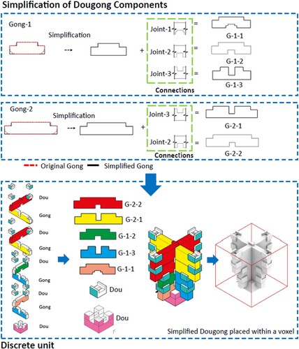
Figure 20. Optimization and voxelisation of the pillar, and the assembly of the prototype fragment of a pillar.
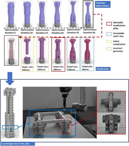
In the third phase, the components were assembled in human-robot collaboration. The robot's tool path was generated in Grasshopper based on the positions of the components within the pillar. During the robotic assembly, some collisions took place which could be caused by discrepancies between the virtual and physical positions of the discrete units within the pillar. An operator used the teach pendant to adjust the coordinates of components that collide with other components to ensure successful assembly. The adjusted coordinates were fed back into Grasshopper to ensure the repeatability of the robotic assembly. The components were produced by an AXYZ ATC 4004 CNC router and assembled by a UR10e robotic arm equipped with a Robotiq 2F-140 gripper. The scripts for the robotic toolpath were generated and simulated in the Rhinoceros/Grasshopper plugin ‘Robots’ and uploaded to the UR controller via the internet.
6. Conclusions
This article reviewed twenty-three articles about applying parametric design and robotics in the design and fabrication of timber-frame structures. The overview showed that only three papers reported directly about the rethinking of the Dougong by utilizing robotic fabrication. The other papers were selected due to the related structures, workflows and robotics related to the topic. The overview stresses that the robotic fabrication of the Dougong is a new area worth exploring. By comparing the geographical distribution of the articles, researchers in Switzerland contributed more work on the topic. The steady increase in publication trends generally indicates a growing interest in the Dougong and timber frame structures joint globally.
It became evident that the digital fabrication of the Dougong required its redesign and adjustment in relation to its original dimensions, connection rules and mechanical properties as high-complexity geometries cause difficulties in fabrication and robotic assembly. Furthermore, its components should undergo discretisation by adopting simple geometry and standard dimensions. The novel Dougon can act as a discrete element and be applied in contemporary design. Using TO and MOO contributed to saving material and improving the stiffness of our discretised Dougong prototype.
Rhinoceros3D and Grasshopper proved to be a widely accepted software package for digital design, optimization and fabrication, especially in the architecture industry since it integrates model generation, mechanical analysis, fabrication simulation and robotic toolpath generation. Overall, Rhinocero3D-Grasshopper was a valid tool for the design and fabrication of our prototype.
The gripper utilized for layer-by-layer assembly appears to be appropriate for the task. The same applies to the electric saw end-effector and the CNC router. The combination of a CNC router and a robotic arm with a gripper appeared to be suitable for fabricating and assembling Dougong elements because of the short operating time, high accuracy and production efficiency.
Furthermore, the proposed workflow, which integrated design, optimization, voxelisation and human-robot collaboration, filled the gap in the application of Dougong in contemporary design. The results of the pillar test proved the feasibility of the proposed design-to-fabrication workflow. The Dougong components were simplified by adjusting dimensions to integer numbers and removing decorative elements, ensuring that the units met the needs of mass production and robotic manufacturing. Voxelisation made it possible to use the Dougong to assemble functional objects such as pillars, but it could also be applied to construct various similar structures. However, the Dougong is a vertical force component, so it could only be applied in vertical force functional objects. The TO and MOO were introduced into the workflow to minimize material usage and optimize the section size of the Dougong components. The pillar test results showed that the optimisations saved 90% of material usage, and its mechanical properties also matched the Chinese timber design codes. The application of human-robot collaboration streamlined the complex manufacturing process of the Dougong joint and minimized the discrepancy between the virtual and physical positions of the Dougong components; the tolerance was reduced to 1 mm, which matched the design codes of the Dougong. Uneven assembly space could cause tolerance discrepancies, leading to collisions during robotic assembly.
Our future research will explore large-scale functional objects as this research was limited to lab size and could only be applied to artefacts of a limited size. In addition, an automatic feeding system will be developed to increase the efficiency of the current workflow.
Disclosure statement
No potential conflict of interest was reported by the author(s).
Data availability statement
Data sharing is not applicable to this article as no new data were created or analysed in this study.
Correction Statement
This article has been corrected with minor changes. These changes do not impact the academic content of the article.
Bibliography
- Adel, Arash, Andreas Thoma, Matthias Helmreich, Fabio Gramazio, and Matthias Kohler. 2018, October 18-20. “Design of Robotically Fabricated Timber Frame Structures.” In Proceedings of the 38th Annual Conference of the Association for Computer Aided Design in Architecture (ACADIA), 394–403.
- Apolinarska, Aleksandra Anna, Matteo Pacher, Hui Li, Nicholas Cote, Rafael Pastrana, Fabio Gramazio, and Matthias Kohler. 2021. “Robotic Assembly of Timber Joints Using Reinforcement Learning.” Automation in Construction 125 (May): 103569. https://doi.org/10.1016/j.autcon.2021.103569.
- Apolinarska, Aleksandra Anna, Davide Tanadini, Fabio Gramazio, and Matthias Kohler. 2021. “Automatic Assembly of Jointed Timber Structure Using Distributed Robotic Clamps.” CAADRIA 124: 1–10.
- Böhme, González, Luis Felipe, Francisco Quitral Zapata, and Sandro Maino Ansaldo. 2017. “Roboticus Tignarius: Robotic Reproduction of Traditional Timber Joints for the Reconstruction of the Architectural Heritage of Valparaíso.” Construction Robotics 1 (1-4): 61–68. https://doi.org/10.1007/s41693-017-0002-6.
- Chai, Hua, Dario Marino, Chun Pong So, and Philip F. Yuan. 2019, October 21-26. “Design for Mass Customization Robotic Realization of a Timber Tower with Interlocking Joints.” In Proceedings of the 39th Annual Conference of the Association for Computer Aided Design in Architecture (ACADIA), 564–572. Austin, Texas: The University of Texas at Austin School of Architecture.
- Chai, Hua, Chunpong So, and Philip F. Yuan. 2021. “Manufacturing Double-Curved Glulam with Robotic Band Saw Cutting Technique.” Automation in Construction 124 (April): 103571. https://doi.org/10.1016/j.autcon.2021.103571.
- Claypool, Mollie, Jane Burry, Jenny Sabin, Bob Sheil, and Marilena Skavara. 2020. “Towards Discrete Automation.” In Fabricate, edited by Burry Jane, Jenny E. Sabin, Bob Sheil, and Marilena Skavara, 272–279. London: UCL Press.
- Dank, Richard, and Christian Freissling. 2013. “The Framed Pavilion.” In Rob | Arch 2012, edited by Brell-Cokcan Sigrid and Johannes Braumann, 238–247. Vienna: Springer Vienna.
- Eversmann, Philipp, Fabio Gramazio, and Matthias Kohler. 2017. “Robotic Prefabrication of Timber Structures: Towards Automated Large-Scale Spatial Assembly.” Construction Robotics 1 (1-4): 49–60. https://doi.org/10.1007/s41693-017-0006-2.
- Heesterman, Mikayla, and Kevin Sweet. 2018. “Robotic Connections: Customisable Joints for Timber Construction.” SIGRADI, 644–652. https://doi.org/10.5151/sigradi2018-1358.
- Koerner-Al-Rawi, Julia, Kyoung Eun Park, Tyson Keen Phillips, Michael Pickoff, and Nichole Tortorici. 2020. “Robotic Timber Assembly.” Construction Robotics 4 (3–4): 175–185. https://doi.org/10.1007/s41693-020-00045-6.
- Kontovourkis, Odysseas. 2017. “Multi-Objective Design Optimization and Robotic Fabrication Towards Sustainable Construction.” eCAADe 35 (2): 125–134.
- Kramberger, Aljaz, Anja Kunic, Iñigo Iturrate, Christoffer Sloth, Roberto Naboni, and Christian Schlette. 2022. “Robotic Assembly of Timber Structures in a Human-Robot Collaboration Setup.” Frontiers in Robotics and AI 8: 768038. https://doi.org/10.3389/frobt.2021.768038.
- Kunic, Anja, Aljaz Kramberger, Roberto Naboni, and The Maersk. 2021. “Cyber-Physical Robotic Process for Re-Configurable Wood Closing the Circular Loop in Wood Architecture.” eCAADe 39 (2): 181–188. https://doi.org/10.52842/conf.ecaade.2021.2.181.
- Kunic, Anja, Roberto Naboni, Aljaz Kramberger, and Christian Schlette. 2021. “Design and Assembly Automation of the Robotic Reversible Timber Beam.” Automation in Construction 123 (December): 103531. https://doi.org/10.1016/j.autcon.2020.103531.
- Lange, Christian J. 2017. “Elements | Robotic Interventions II.” eCAADe 35 (1): 671–678. https://doi.org/10.52842/conf.ecaade.2017.1.671.
- Leopold, Cornelie, Christopher Robeller, and Ulrike Weber. 2019. “Cooperative Robotic Fabrication of Timber Dowel Assemblies.” Research Culture in Architecture (December): 77–88. https://doi.org/10.1515/9783035620238.
- Liang, Sicheng. 2006. “Gong Chen Zuo Fa” Graphic. Beijing City: Tsinghua University Press.
- Long, Zhang, Chang Zhenning, Li Qian, and Zhou Ting. 2020. “Experimental Research on the Anti-Seismic Properties of a Five-Stamping Tou-Kung Joint of Ancient Chinese Buildings in the Ming Dynasty: A Case Study of Guang-yue Tower in Liaocheng City, Shandong Province.” International Journal of Architectural Heritage 14 (9): 1360–1372. https://doi.org/10.1080/15583058.2019.1607626.
- Ma, Bingjian. 2003. “Chinese Ancient Architecture Woodwork Construction Technology.” China Science Publishing & Media 224–250.
- Makki, Mohammed, Milad Showkatbakhsh, Aiman Tabony, and Michael Weinstock. 2018. “Evolutionary Algorithms for Generating Urban Morphology: Variations and Multiple Objectives.” International Journal of Architectural Computing 17 (1): 5–35. https://doi.org/10.1177/1478077118777236.
- MOHURD. 1992. GB 50165-1992-Technical Code for Maintenance and Strengthening of Ancient Timber Buildings. Beijing City: China Architecture & Building Press.
- Morse, Christopher, Erik Martinez-Parachini, Philip Richardson, Charlie Wynter, and John Cerone. 2020. “Interactive Design to Fabrication, Immersive Visualization and Automation in Construction.” Construction Robotics 4 (3-4): 163–173. https://doi.org/10.1007/s41693-020-00039-4.
- Mostafavi, Sina, Valmir Kastrati, Hossam Badr, Shazwan Mazlan, Wood Assembly, and Reciprocal Tessellation. 2020. “Design Computation to Robotic Production Methods for Reciprocal Tessellation of Free-from Timber Structures Design, Production, and Assembly of 100 Years Bauhaus Wood Pavilion.” eCAADe 38 (2): 413–422. https://doi.org/10.52842/conf.ecaade.2020.2.413.
- Naboni, Roberto, and Anja Kunic. 2020. “A Computational Framework for the Design and Robotic Manufacturing of Complex Wood Structures.” eCAADe 37 (3): 189–196. https://doi.org/10.5151/proceedings-ecaadesigradi2019_488.
- Preisinger, Clemens. 2013. “Linking Structure and Parametric Geometry.” Architectural Design 83 (2): 110–113. https://doi.org/10.1002/ad.1564.
- Retsin, Gilles, Jane Burry, Jenny Sabin, Bob Sheil, and Marilena Skavara. 2020. “Discrete Timber Assembly.” In Fabricate, edited by Burry Jane, Jenny E. Sabin, Bob Sheil, and Marilena Skavara, 264–271. London: UCL Press.
- Takabayashi, Hiroki, and Keita Kado. 2019. Robotic Fabrication in Architecture, Art and Design 2018. Cham, Switzerland: Springer International Publishing.
- Willmann, Jan, Michael Knauss, Tobias Bonwetsch, Anna Aleksandra Apolinarska, Fabio Gramazio, and Matthias Kohler. 2016. “Robotic Timber Construction – Expanding Additive Fabrication to New Dimensions.” Automation in Construction 61 (January): 16–23. https://doi.org/10.1016/j.autcon.2015.09.011.
- Xian, Ziju, Nicholas Hoban, and Brady Peters. 2020. “Spatial Timber Assembly: Robotically Fabricated Reciprocal Frame Wall.” eCAADe 38 (2): 403–412. https://doi.org/10.52842/conf.ecaade.2020.2.403.