
 ?Mathematical formulae have been encoded as MathML and are displayed in this HTML version using MathJax in order to improve their display. Uncheck the box to turn MathJax off. This feature requires Javascript. Click on a formula to zoom.
Abstract
The present study deals with sensorless fault-tolerant control (SFTC) of five-phase Interior Permanent Magnet Synchronous Motors (IPMSMs). First, a Proportional-Integral Model Reference Adaptive System (PI-MRAS) speed estimator is proposed. The MRAS compares outputs of reference and adaptive models. Then, PI controller is utilized to generate the estimated speed by minimizing current errors between the two models. Second, a novel Sign Integral Terminal Sliding Mode Controller (SITSMC) is suggested in the presence of open phase faults. The proposed controller tolerates these faults through a transformation matrix tuning technique in view of equal current and minimum copper loss schemes. Meanwhile, SITSM controller utilizes the estimated speed of PI-MRAS block. Third, stability of the closed-loop system is provided by Lyapunov theorem. Finally, simulation results validate the feasibility and effectiveness of the suggested SFTC strategy both in normal and open one phase faulty conditions for a five-phase IPMSM.
1. Introduction
Nowadays, the multi-phase permanent magnet synchronous motors (PMSMs) are one of the most exciting candidates in high tech processes such as military applications, aerospace, marine applications and the electric vehicles [Citation1–3]. High-power density, lower current per phase without increasing the stator voltage, high efficiency, and the lower torque ripples are the brilliant advantages of multi-phase IMPSMs. Furthermore, multi-phase PMSMs are able to proceed their operation with one or even two lost phases, which increases the reliability of the processes [Citation4–6].
Field Oriented Control (FOC) is one of the most common techniques for speed control of multi-phase PMSMs [Citation6]. This technique allows to deal with the five-phase IPMSM like a DC motor by decoupling and transferring the equations from the stationary reference frame abcde to the rotary reference frame with a zero-sequence variable [Citation7]. The FOC aims to control the current vector, while it needs accurate data of the rotor speed or position. In this regard, different sensors like the resolvers and encoders have been proposed [Citation8]. However, a special motor construction is required to mount the sensors in the IPMSM drive. In addition, speed sensor installation increases the system costs on one hand and decreases the system reliability on the other hand [Citation9,Citation10]. Thus, driving the five-phase IPMSMs without speed or position sensors is an interesting topic and various estimators have been devoted including high frequency injection with an observer [Citation9], sliding mode observer [Citation10], Kalman filter [Citation11] and MRAS [Citation12].
The MRAS is one of the simple methods to estimate the rotor position and speed. This method ensures the estimator convergence via Popov’s hyper stability theory [Citation12,Citation13]. In this regard, the rotor speed is estimated by PI-MRAS structure which considers the stator currents or rotor fluxes as the state variables [Citation14,Citation15]. The MRAS has been used in lots of studies for speed estimation of three-phase PMSM and Induction Motors (IMs). However, there are few papers about investigating of MRAS for five-phase IMs [Citation15,Citation16]. To the author’s best knowledge, the MRAS technique has not been applied as the speed/position estimator for five-phase IPMSMs.
Once a system encounters with partial faults such as sensor faults, it will cause the loss of global control objectives. Therefore, it is important to compensate for the effect of faults, which can improve the security and reliability of systems [Citation17–19]. The IPMSMs may encounter with different faults. These faults can be categorized as follows [Citation20]: (a) Mechanical faults such as bearing damages and rotor eccentricities. (b) Magnetic faults such as demagnetization. (c) Electrical faults such as the open phase and short circuit faults. (d) Other equipment’s faults such as sensors faults.
The open phase fault is the most common fault which occurs in the supply disconnection or winding disconnection inside the stator in a star connection. Open phase fault causes the Magneto Motive Force (MMF) oscillations, speed reduction, ripples, current increasing, and deformation which may imply winding damages [Citation21]. Thus, compensating the open phase fault effects is necessary for five-phase IPMSMs.
The open phase fault can be detected through the associated phase current sensor. Thus, the control scheme should switch to the related Fault-Tolerant Control (FTC) algorithm. This method is simple and straightforward, however, it has some disadvantages like delay existence and sensor failure [Citation22,Citation23]. Thus, some online fault detection methods have been proposed in the literature for the three and multi-phase motors [Citation23,Citation24]. The present study is focused on the open phase fault detection through the current sensors.
There is no doubt that the sliding mode control (SMC) is a very effective and useful control technique and has plenty of advantages like containing a robust and accurate behaviour [Citation25,Citation26]. Because of these advantages, SMC has been used in many linear, nonlinear, uncertain, stochastic and faulty systems etc. [Citation27–29]. In this method, two main types of surfaces including the linear and nonlinear sliding surfaces have been suggested [Citation30,Citation31]. It is worthy to state that the nonlinear sliding surface is also known as a terminal sliding surface. The terminal sliding surface shows fast and high precision response vs. the linear sliding surface [Citation7]. In the basis of the noted benefits, the Terminal Sliding Mode Control (TSMC) seems to be a powerful technique for fault tolerance.
The FTC along with the sliding mode observation/control techniques has been studied in lots of papers. Combining fault-tolerant sliding mode controller with delta operator or fuzzy T-S model covers nonlinear systems actuator faults [Citation28–30]. The TSM controllers for three-phase PMSM have been studied in [Citation31–35] and recently have been used for five-phase PMSM in the normal and opened phase faulty states [Citation36–38]. To the author’s best knowledge, there are few researches around designing the FTC in view of TSM for five-phase IPMSM [Citation39].
In view of the foregoing discussion, we are going to propose, a SFTC strategy to control/estimate the mechanical speed and compensate the open phases fault of five-phase IPMSM. Comparative simulations validate the effectiveness of the suggested SFTC (SITSMC + PI-MRAS). The main contributions of the suggested method are as follows:
A novel SITSM controller is designed in both normal and open one phase faulty conditions. The main idea of this method is the total MMF maintenance in the normal and faulty states.
A PI-MRAS speed estimator is developed to reduce the speed sensor cost.
Both of the equal current and minimum copper losses fault-tolerant schemes are investigated in the proposed SFTC.
The rest of this paper is organized as follows. Section 2 presents a mathematical model for five-phase IPMSM. Two fault-tolerant schemes are introduced in Section 3. The PI-MRAS speed estimator is developed in Section 4. Section 5 proposes a novel SITSM controller which employs the estimated speed instead of measures speed. The closed-loop system configuration is explained in Section 6. Section 7 simulates various scenarios to show the performance of the proposed control strategies. The Conclusion Section concludes the paper.
2. Five-phase IPMSM mathematical model
A five-phase IPMSM mathematical model in the rotating reference frame is presented as follows [Citation1]:
(1)
(1)
where ,
,
and
are
-axis voltages,
denote the stator currents,
is the stator resistance,
,
and
represent the stator flux-linkage components,
and
are the
-axis inductances,
and
are the electrical and mechanical angular velocities,
denotes the electrical torque,
is the number of poles,
represents the rotational inertia,
is the friction factor and
shows the motor load.
The stator flux-linkage relations with the stator currents are given as
(2)
(2) where
represents the rotor permanent magnet flux-linkage,
is the
-axis inductance, and
denote the
-axis mutual inductances.
Substituting the flux linkage relations (2) in (1), gives us the five-phase IPMSM mathematical model as
(3)
(3) It is worthwhile to mention that the pseudo orthogonal transformation matrix that transfers the abcde stationary reference frame variables of five-phase IPMSM into the
rotating reference frame is defined by [Citation1].
(4)
(4) where θ is the rotor electrical angular position.
3. MMF of five-Phase IPMSM in normal and faulty conditions
The Multi-phase machines are potentially fault tolerant to open phase faults in a closed-loop control drive [Citation1]. In other words, maintenance of the total MMF without one phase is possible.
The stator MMFs in view of the stator windings sinusoidal distribution is given by [Citation1,Citation2]:
(5)
(5) where N denotes the total number of turns for each phase, “
” represents the spatial angle, Im shows the amplitude of the phase currents and
where
is the electrical angular speed.
Since the total MMF of stator is aggregation of all the phases MMFs, thus one finds
(6)
(6) which is given by
(7)
(7)
On the other hand, the total MMF is expressed as
(8)
(8) Comparing (7) and (8), results in (9) in a healthy condition.
(9)
(9)
Now, assume that phase “a” is opened by the winding faults or disconnections in the power transmission wires, keeping the total MMF level with the remaining four phases is possible in infinite ways. Equal current scheme and minimum copper losses schemes are two of the aforementioned ways to keep the total MMF in a certain range in our design.
3.1. Equal currents scheme
In equal current scheme, the idea for maintaining the same MMF is considering the current pairs equal and opposite as [Citation1]: ,
. This consideration implies that
(10)
(10) Therefore, the stator currents (when phase “a” is open) can be expressed in the following
reference frame as
(11)
(11)
The Equation (11) is given in the following transfer matrix form [Citation35].
(12)
(12)
3.2. Minimum copper losses scheme
Another scheme to manage the total MMF level is known as minimum copper losses. In this method, the remained four healthy currents can be considered as follows [Citation39]:
(13)
(13) where
and
are constants that can be calculated. To keep the MMF with the remained four phases in (9), one has
(14)
(14)
Utilizing (13) and (14), yields
(15)
(15) Another constraint is
, which gives us
(16)
(16)
To minimize the copper losses, the target function “” is defined as below
(17)
(17) Now, the target function should be minimum in view of (15) and (16) constraints. Applying the genetic algorithm (GA) obtains the optimal currents
(18)
(18)
The results are expressed based on the fact that can be represented with one sine function
where
and
.
4. Model reference adaptive system for five-Phase IPMSM
Our paper is going to propose a sensorless control scheme based on the MRAS on a five-phase IPMSM for the first time. The MRAS algorithm compares the outputs of reference and adaptive models. An adaptive mechanism based on PI controller is utilized to generate the estimated speed by minimizing the error between the reference and adaptive models. This concept is presented in Figure .
Figure 1. Schematic diagram of MRAS.
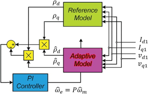
According to (1), only currents are involved in the torque production. Then, by considering that
,
,
and
, the reference and adaptive models of Figure can be expressed by (19) and (20), respectively.
(19)
(19)
(20)
(20)
Accordingly, the estimated speed can be obtained as
(21)
(21) where
and
are the proportional and integral parameters
.
5. Sign integral terminal sliding mode controller for five-Phase IPMSM
In this section, a novel fault-tolerant controller is proposed for the speed control of five-phase IPMSM. According to Equation (1), when and
, the electrical torque is given by
(22)
(22) Thus, by defining the parameters
,
,
, one obtains
(23)
(23)
Let us rewrite (23) along with the estimated speed , thus one finds
(24)
(24) where
is the sum of lumped uncertainties.
Now, consider the following error and sliding surface for the speed control
(25)
(25)
(26)
(26) where
.
By taking the time derivative of (26) and substituting (24), one obtains
(27)
(27) To stabilize (27) dynamics, the control law is suggested as
(28)
(28)
THEOREM 1: Consider the sliding surface (26) with the sliding surface dynamic (27), thus the control law (28) guarantees the rotor speed error zero convergence.
Proof Let us consider the following Lyapunov candidate function:
(29)
(29) Taking the time derivative from (29) in view of (27)–(28), results in
Thus, one finds
(31)
(31)
Inequality (31) assures the sliding surface zero convergence for .
It is worthy to mention that the reference currents in axis managed to be zero in order to reduce the power losses.
6. Simulations
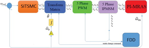
The schematic diagram of five-phase IPMSM control process in faulty mode through the proposed approach is illustrated in Figure . This figure contains the five-phase IPMSM, SITSM controller, five-phase PWM, speed estimation block through PI-MRAS, transformation matrix and finally the Fault Detection and Diagnosis (FDD) blocks.
Figure 2. SFTC schematic diagram for five-phase IPMSM.
The five-phase IPMSM parameters are listed in Table .
Table 1. Parameters of five-phase IPMSM.
Simulations have been carried out in MATLAB/Simpower environment to verify the effectiveness of the suggested control strategy. Simulations are performed with a 100-kHz switching frequency. Furthermore, the proposed SFTC (PI-MRAS + SITSMC) strategy parameters are listed in Tables and .
Table 2. Parameters of PI-MRAS.
Table 3. Parameters of SITSMC.
To consider the motor drive limitations in practice, the control signal is limited to 50 A by a saturation block. Moreover, a low pass filter is applied to the controller output signal in order to reduce the chattering effects. The filter cutoff frequency has been adjusted to .
In the following subsections, the analyses proceed in the normal and open phase faulty conditions with equal current and minimum copper loss fault tolerance techniques. Moreover, multiple comparative simulations are done to show the proposed method effectiveness and performance.
Normal drive
The developed strategy performance is validated in the normal drive under the following changes:
The initial reference speed is set to at
, and it is increased to
at
.
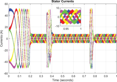
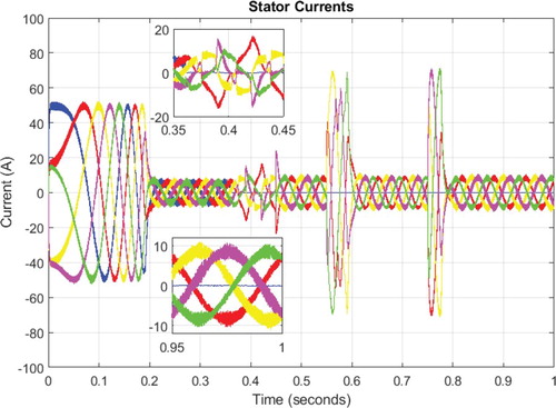
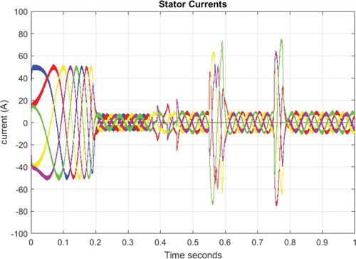
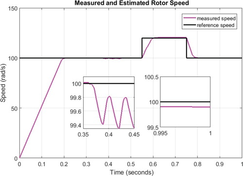
Figures – demonstrate the simulation results of SFTC method in the presence of the above changes. All of these figures contain some sectional extra zoom to provide more information. Figure and 4 indicates the reference, estimated and measured rotor speeds. This figure shows that the rotor estimated speed is converged to the measured value. Moreover, the estimated speed tracks the reference value very well. In Figure , the IPMSM torque is demonstrated which is kept constant unless during the motor start time and the reference speed variations. Moreover, the stator currents have been presented in Figure . The amplitude of currents are high during the motor start time and the reference speed variations, while they are well arranged at the next moments.
| (B) | Open phase fault with the equal current scheme | ||||
Figure 3. Measured and reference rotor speed in the normal drive.
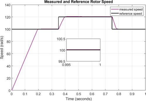
Figure 4. Measured and estimated rotor speed in the normal drive.
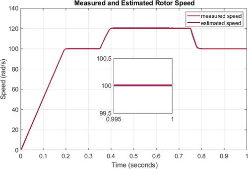
Figure 5. Motor torque in the normal drive.
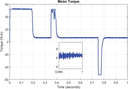
Figure 6. Stator currents in the normal drive.
The suggested SFTC strategy under the open one phase fault along with the equal current scheme tolerance is tested on the following changes:
The initial reference speed is set to
at
The open phase fault is set to
Figures –, are indicating the simulation results of SFTC in the presence of the stated changes. Figures and illustrates the reference, estimated and measured rotor speeds. In these figures, it is clear that the estimated rotor speed is converged to the measured speed, and the measured speed is converged to the reference value with small amount of tracking error. Moreover, the speed estimation/tracking is well even during the faulty time interval. The motor torque and stator currents are displayed in Figures and , respectively. It can be seen that SFTC approach reaction is excellent against the open one phase fault in view of equal current fault-tolerant scheme.
| (C). | Open phase fault with the minimum copper loss scheme | ||||
Figure 7. Measured and reference rotor speed in the open phase fault in view of equal current scheme.
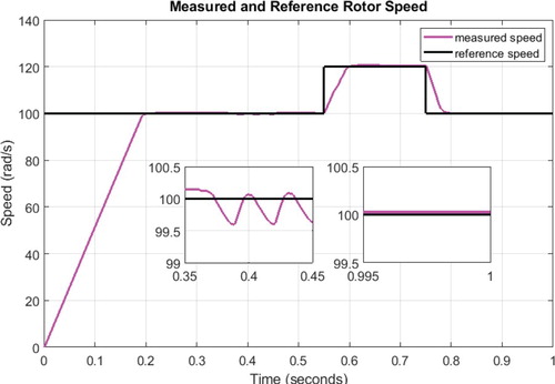
Figure 8. Measured and estimated rotor speed in the open phase fault in view of equal current scheme.
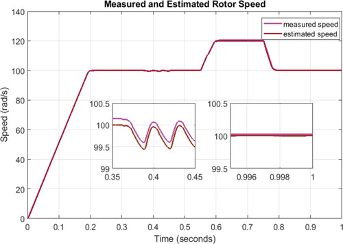
Figure 9. Motor torque in the open phase fault in view of equal current scheme.
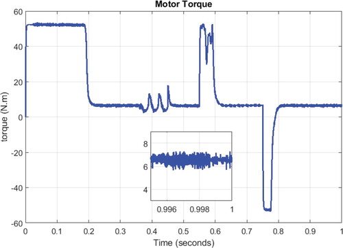
Figure 10. Stator currents in the open phase fault in view of equal current scheme.
The proposed SFTC method under the open phase fault with the minimum copper loss scheme is validated in the following conditions:
The initial reference speed is set to
The open phase fault is set to
Figures –, demonstrate the simulation results of SFTC in the presence of the noted changes. Figures and illustrate the reference, estimated and measured rotor speeds. These figures exhibit that the estimated rotor speed is converged to the reference/measured speed with small errors even in the faulty times. Figures and , represent the motor torque and stator currents. It is evident that SFTC strategy reaction is superb against the open one phase fault in view of minimum copper loss fault-tolerant scheme.
| (D). | Comparative simulations | ||||
Figure 11. Measured and reference rotor speed in the open phase fault in view of minimum copper loss scheme.
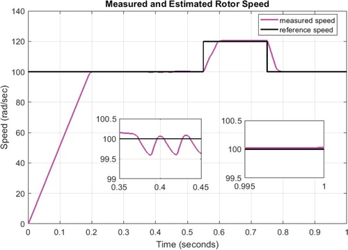
Figure 12. Measured and estimated rotor speed in the open phase fault in view of minimum copper loss scheme.
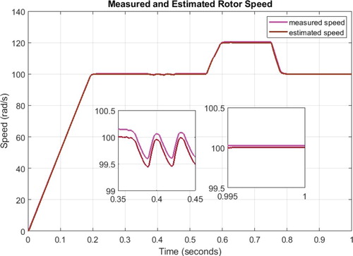
Figure 13. Motor torque in the open phase fault in view of minimum copper loss scheme.
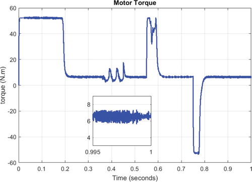
Figure 14. Stator currents in the open phase fault in view of minimum copper loss scheme.
To compare the proposed method effectiveness with the existing methods, a common fuzzy-PI controller with 25 rules for each gain has been designed according to [Citation12]. It is worthy to notify that the proposed SITSMC and fuzzy-PI controllers are utilizing the same PI-MRAS observer and transformation matrix. The rotor speed for the normal drive, and open phase fault-compensation schemes are demonstrated in Figures –.
Figure 15. Measured and reference rotor speed with sensorless fuzzy-PI strategy in the normal drive.
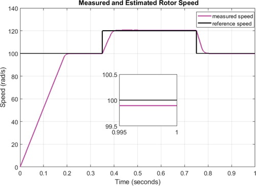
Figure 16. Measured and reference rotor speed with sensorless fuzzy-PI strategy in view of equal current scheme.
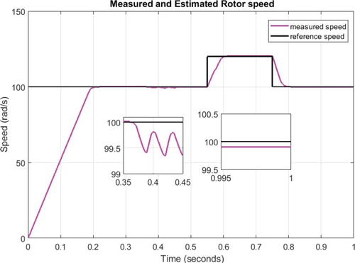
Figure 17. Measured and reference rotor speed with sensorless fuzzy-PI strategy in view of minimum copper loss scheme.
From Figures –, it is evident that the proposed SITSMC shows less tracking errors in comparison with the sensorless fuzzy-PI controller in the normal and faulty conditions. The speed estimation error and modelling imperfections are the main reasons of the steady-state tracking errors existence in Figures –. Moreover, the fault occurrence at 0.35 sec is another cause of the steady-state tracking errors for the sensorless fuzzy-PI in Figures –, while the proposed robust controller is able to reduce the tracking errors progressively.
7. Conclusion
In this paper, SFTC strategy is designed and developed for five-phase IPMSMs. In the first step, the PI-MRAS speed estimator is proposed. The MRAS compares the current outputs of the reference and adaptive models. Then, PI controller is applied to generate the estimated speed by minimizing the output errors between the two models. In the second step, SITSMC is designed in the presence of open phase faults. The suggested controller tolerates these faults through the transformation matrix in view of the equal current and minimum copper loss schemes. Meanwhile, SITSM controller utilizes the estimated speed of PI-MRAS block. In the third step, stability of the closed-loop system is dscussed by Lyapunov theorem. Finally, the simulation results confirm the feasibility and effectiveness of the proposed SFTC strategy both in the normal and open one phase faulty conditions. The suggested sensorless control strategy is able to detect and tolerate the opened phase fault very well in comparison with the sensorless fuzzy-PI method. Moreover, the speed estimation/tracking errors of five-phase IPMSM are so small even during the fault occurrence.
Disclosure statement
No potential conflict of interest was reported by the authors.
References
- Parsa L, Toliyat HA. Fault-tolerant interior-permanent magnet machines for hybrid electric vehicle applications. IEEE Trans Veh Technol. 2007;56(4):1546–1552.
- Ben Sedrine E, Ojeda J, Gabsi M, et al. Fault tolerant control using the GA optimization considering the reluctance torque of a five-phase flux switching machine. IEEE Trans Energy Convers. 2015;30(3):927–938.
- Hosseyni A, Trabelsi R, Mimouni MF, et al. Sensorless sliding mode observer for a five-phase permanent magnet synchronous motor drive. ISA Trans. 2015;58(1):462–473.
- Scuiller F, Semail E, Charpentier J-F, et al. Multi criteria-based design approach of multi-phase permanent magnet low-speed synchronous machines. IET Electr Power Appl. 2009;3(2):102–110.
- Mohammadpour A, Parsa L. A Unified fault-tolerant current control approach for five-phase PM motors with Trapezoidal Back EMF under different stator winding connections. IEEE Trans Power Elec. 2013;28(7):3517–3527.
- Betin F, Capolino G-A, Casedi D, et al. Trends in electrical machines control: samples for classical, sensorless, and fault-tolerant techniques. IEEE Ind Electron Mag. 2014;8(2):43–55.
- Zafari Y, Mazinan AH, Majidabad SS. Demagnetization fault detection for five-phase IPMSM through integral terminal sliding mode flux-linkage observer. IETE J Res. 2019;65(4):473–486.
- Boussak M. Implementation and experimental investigation of sensorless speed control with initial rotor position estimation for interior permanent magnet synchronous motor drive. IEEE Trans Power Electron. 2005;20(6):1413–1422.
- Allampalli RS, Mangsuli PR, Chatterjee K. Novel compensation method to reduce rotor position estimation error and torque reduction in signal injection based PMSM drives. Int J Power Electron Drive Syst. 2017;8(2):548–555.
- Baratieri CL, Pinheiro H. New variable gain super-twisting sliding mode observer for sensorless vector control of nonsinusoidal back-EMFPMSM. Control Eng Pract. 2016;52(1):59–69.
- Bolognani S, Tubiana L, Zigliotto M. Extended Kalman filter tuning in sensorless PMSM drives. IEEE Trans on Industry App. 2013;39(17):1741–1747.
- Liu Y, Wan J, Li G, et al. MRAS speed identification for PMSM based on Fuzzy PI control. Industrial Electronics and Applications, 2009. ICIEA 2009. 4th IEEE Conference on, pp.1995–1998.
- Pewmaikam C, Srisertpol J, Khajorntraidet C. Adaptive fuzzy Logic Compensator for permanent magnet synchronous motor torque control system. Int J Model Optim. 2012;2(2):141–146.
- Cheng M, Hua W, Zhang B. Sensorless control strategy of electrical variable transmission machines for Wind Energy Conversion systems. IEEE Trans Magnetics. 2013;49(7):3383–3386.
- Morsy AS, Abdel-khalik AS, Ahmed S, et al. Sensorless V/f control with MRAS speed estimator for a five-phase induction machine under open-circuit phase faults .2013 IEEE GCC Conference and exhibition. November 17–20, Doha, Qatar: p. 268–273.
- Abu-Rub H, Rizwan Khan M, Iqbal A, et al. MRAS-based sensorless control of a five-phase induction motor drive with a predictive adaptive model. Industrial Electronics (ISIE), 2010 IEEE International Symposium on, pp. 3089–3994.
- Zhang L, Lam HK, Sun Y, et al. Fault detection for fuzzy Semi-Markov Jump systems based on interval Type-2 fuzzy approach. IEEE Trans Fuzzy Syst. 2019. doi:10.1109/TFUZZ.2019.2936333.
- Cao L, Li H, Dong G, et al. Event-triggered control for multi-agent systems with sensor faults and Input saturation. IEEE Trans Syst Man Cybern Syst. 2019. doi:10.1109/TSMC.2019.2938216.
- Zhang L, Liang H, Sun Y, et al. Adaptive event-triggered fault detection for semi-Markovian jump systems with output quantization. IEEE Trans Syst Man Cybern Syst. 2019. doi: 10.1109/TSMC.2019.2912.
- Moosavi SS, Djerdir A, Amirat YA, et al. Demagnetizationfault diagnosis in permanent magnet synchronous motors: a review of the state-of-the-art. J Magn Magn Mater. 2015;351:203–212.
- IEEE recommended practice for the design of reliable industrial and commercial power systems. Technical report, IEEE. doi:10.1109/IEEESTD.1998.89291.
- Taherzadeh M, Carriere S, Betin F, et al. A novel strategy for sensorless control modification of a six-phase induction generator in faulted mode. Electric Power Compon Sys. 2016;44(8):941–953.
- Duran MJ, Gonzalez-Prieto I, Rios-Garcia N, et al. A simple, fast and robust open-phase fault detection technique for six-phase induction motor drives. IEEE Trans on Power Elec. 2018;33(1):547–557.
- Yang SH, Hsu YL, Chou PH, et al. Online open-phase fault detection for permanent magnet machines with low fault harmonic magnitudes. IEEE Trans on Industrial Elec. 2018;65(5):4039–4050.
- Majidabad SS, Shandiz HT. Discrete-time based sliding mode control of robot manipulators. Int J Intell Comput Cybern. 2012;5(3):340–358.
- Majidabad SS, Shandiz HT, Hajizadeh A. Nonlinear fractional-order power system stabilizer for multi-machine power systems based on sliding mode technique. Int J Robust Nonlinear Control. 2015;25(10):1548–1568.
- Wu L, Gao Y, Liu J, et al. Event-triggered sliding mode control of stochastic systems via output feedback. Automatica (Oxf). 2017;82(1):79–92.
- Wang J, Gao Y, Qiu J, et al. Sliding mode control for non-linear systems by Takagi–sugeno fuzzy model and delta operator approaches. IET Control Theory Applic. 2017;11(8):1205–1213.
- Gao Y, Wu L, Shi P, et al. Sliding mode fault-tolerant control of uncertain system: a delta operator approach. Int J Robust Nonlinear Control. 2017;27(18):4173–4187.
- Li S, Zhou M, Yu X. Design and implementation of terminal sliding mode control method for PMSM speed regulation system. IEEE Trans Industrial Informatics. 2012;9(4):1879–1891.
- Gao Y, Liu J, Sun G, et al. Fault deviation estimation and integral sliding mode control design for Lipschitz nonlinear systems. Syst Control Lett. 2019;123(1):8–15.
- Zhang X, Sun L, Zhao K, et al. Nonlinear speed control for PMSM system using sliding-mode control and disturbance compensation techniques. IEEE Trans Power Electron. 2013;28(3):1358–1365.
- Xu W, Jiang Y, Mu C. Novel composite sliding mode control for PMSM drive system based on disturbance observer. IEEE Trans Appl Supercond. 2016;26(7):1–5.
- Zafari Y, Majidabad SS. Robust flux observer and robust block controller design for interior permanent magnet synchronous motor under demagnetization fault. Int J Model Ident Control. 2018;30(3):206–218.
- Baik I-C, Kim K-H, Youn M-J. Robust nonlinear speed control of PM synchronous motor using boundary layer integral sliding mode control technique. IEEE Trans Control Syst Technol. 2000;8(1):47–54.
- Tian B, An Q-T, Duan J-D, et al. Decoupled modeling and nonlinear speed control for five-phase PM motor under single phase open fault. IEEE Trans Power Electron. 2017;32(7):5473–5486.
- Tian B, An Q-T, Duan J-D, et al. Cancellation of torque ripples with FOC strategy under two phase failures of five-phase PM motor. IEEE Trans Power Electron. 2017;32(7):5459–5472.
- Zafari Y, Mazinan AH, Majidabad SS. Speed control of five-phase IPMSM through PI, SMC and FITSMC approaches under normal and open phase faulty conditions. Automatika. 2018;58(4):506–519.
- Gu G, Zhao W, Zhang B. Simplified minimum copper loss Remedial control of a five-phase fault-tolerant permanent-magnet Vernier Machine under short-circuit fault. Energies. 2016;9(1):860–875.