
 ?Mathematical formulae have been encoded as MathML and are displayed in this HTML version using MathJax in order to improve their display. Uncheck the box to turn MathJax off. This feature requires Javascript. Click on a formula to zoom.
ABSTRACT
In the context of larger renewable energy harnessing, combining offshore wind farm (OWF) and marine current farm (MCF) at the same location is often found suitable in terms of geographical conditions and economic reasons. However, stochastic nature of wind speed and marine current speed with increased penetration level significantly affects the system stability, grid voltage and raises some control and stability problem; furthermore, the parametric uncertainty of generators brings additional challenges under grid voltage distortion. Therefore, in this article, we present a consolidated application of STATCOM and BFCL in the context of stability assessment of integrated system. Consequently, a robust H∞ loop-shaping controller has been proposed in the presence of parametric uncertainties. In this context, optimizing controller performance with respect to the undesired parametric uncertainties and external disturbances has been proposed. The control effort is initiated by formulating the robust H∞ loop-shaping controller in the context of evaluating the controller parameters and gain with respect to desired robust stability margin. The efficacy of the proposed control scheme is measured through different case studies in real time digital simulation (RTDS) environment. The comparative analysis of simulation results demonstrates the effectiveness of the proposed control strategy in the context of integrated system stability and reliability.
1. Introduction
The remarkable growth of power demand worldwide and concerns for protection of environment have renewed interest in large-scale investments in non-conventional energy options. In the last couple of years, OWF has been found attractive as an energy solution and is being considered as an alternate resource for considerable electricity generation. The ocean has untapped energy resources in the form of tidal wave [Citation1], geothermal, offshore wind etc. at different geographical locations. They form formidable energy resources especially in the Gulf Stream, Florida straight and California straight which is capable of making up for a large share of the future energy needs. OWF combined with MCF, owing to their natural availability in close proximity, would become a new kind of integrated energy generation system in near future. Further high correlation between offshore wind energy and marine current energy operating characteristic is arguably convenient of grid integration without raising much ancillary issues to address. However, the wind energy and marine current energy resources are stochastic in nature. Thus, high penetrations of OWF and MCF into the national grid rise some critical issues of stability [Citation2,Citation3] power quality and fault ride through the ability of the integrated system and the grid code requirement [Citation4,Citation5] takes a nose dive to take care of such issues.
One of the simple methods of running an OWF is to aggregate several doubly fed induction generator (DFIG)-based generator driven by offshore wind turbine and then connected to on-shore grid through step-up transformers and under-sea cables. Similarly, to run a marine current farm (MCF), we may use an aggregated model of squirrel cage induction generator (SCIG)-based generator driven by marine current turbine, directly connected to the grid through step-up transformers and under-sea cables. Both WTs and MCTs have similar operating characteristic, but SCIG required reactive power for magnetization, while DFIG operates close to unity with the control of back to back PWM converters. The active power generated by an SCIG-based MCF is varied because the stochastic nature of marine current speed, the absorbed reactive power and terminal voltage are significantly affected. These generators are very sensitive to the voltage distortion, e.g. grid faults, when connecting large-scale high capacity OWF and MCF to the power grid a fact device or a control device is required to compensate the power fluctuations and grid voltage distortion under dynamic or transient conditions. Also required are current limiting devices to limit the transient current and improve the stability of the studied system. In this context, the authors used the aggregated model of DFIG-based generator for OWF and MCF is modelled by the aggregated model of SCIG-based generator driven by marine current turbine that is integrated with STATCOM and bridge type fault current limiter (BFCL). Voltage fluctuations, current harmonics, unbalance current and change in flux density create overheating [Citation6] in the generator windings and other control problems are common with integrated system. Due to this, the parameters of the generator and associated devices are varying, the variation in parameters is considered as a parametric uncertainty which affects the control signals of the studied system [Citation7].
Various FACTS controllers, fault current limiters and control techniques are proposed to address the power oscillation damping, voltage distortions and stability of the system. The authors in [Citation8] have discussed the stability enhancement of grid-interactive OWF and MCF using STATCOM. A PID-based damping controller has been proposed to enhance the dynamic and transient stability of an integrated system without considering the uncertainty present in the system. In [Citation9], a robust control is proposed for wind farm consisting of STATCOM, it is not fully explored the parametric uncertainty in controller design. In [Citation10], authors discuss the FSIG/DFIG-based WTGs directly connected to a weak grid with unified power quality compensators (UPQCs) and investigate the reactive power compensation and enhancement of voltage stability, FRT capability. In [Citation11], a comparative study of reactive power compensation to WTGs directly connected to the AC grid is performed to investigate the efficacy of the STATCOM, static synchronous series compensator (SSSC) and static VAR compensator (SVC).
Consequently, various control techniques have been reported in the literature, some of these control techniques are proportional integral and resonant control [Citation12–14] or fuzzy logic-based control [Citation15] or sliding mode control [Citation16] or predictive control [Citation17] which may give optimal performance if system parametric uncertainty is fully considered. The authors in [Citation18] proposed a sliding mode control-based controller for variable speed WTs and similarly in [Citation19] authors have proposed a fuzzy logic-based controller for grid-integrated WTs. These controllers can give satisfactory performance when the parametric uncertainty or disturbance is considered in controller design. In [Citation20,Citation21] authors have discussed repetition control and predictive direct power control under grid voltage distortion. They have not fully explored the parametric uncertainties present in the system. In [Citation22–25], the authors have proposed an adaptive current control regulator for grid-connected PV solar applications. They have explored the harmonic suppressions present in the grid PV system and proposed robust fuzzy logic-based active filter to prevent malfunctioning of devices.
The controller, based on the robust H∞ control, considers all parametric uncertainty and exogenous input in the controller design [Citation26]. It gives satisfactory performance and achieves robustness under parametric uncertainty and exogenous disturbance [Citation27]. Many electrical control fields have successfully used the H∞-based robust controllers, such as dynamic voltage restorer (DVR), uninterruptible power supplies (UPS) and voltage source inverter (VSI) [Citation28,Citation29].
To the best of the authors’ knowledge, none of the existing research papers fully explore the consolidated and simultaneous application of STATCOM and BFCL and their dynamic behaviour in transient and steady-state conditions. Thus, this paper proposed a robust H∞ controller of the hybrid system that consists of OWF, MCF, STATCOM and BFCL under parametric uncertainty, to achieve power flow control and stability of the studied system. The performance of the proposed controller is evaluated under dynamic and transient scenario.
The paper is organized as follows: mathematical modelling of OWF, MCF, STATCOM and BFCL is given in Section 2, time domain and frequency domain analysis based on simulation results are presented in Section 3, results and discussion is given in Section 4.
2. System configuration
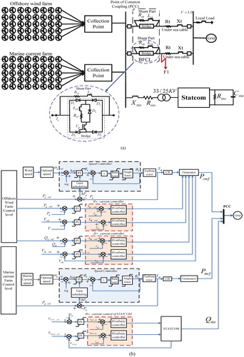
A DFIG-based OWF and SCIG-based MCF is used as a system simulation, as shown in Figure (a). It has included BFCL and STATCOM at the PCC, the centralized control schemes are represented in Figure (b). Twenty DFIGs are aggregated to a 40MW OWF, whereas twenty SCIGs are combined to deliver a 40MW MCF. DFIGs were used for the variable wind speed turbines, while SCIGs were used for variable speed marine current turbines. Both OWF and MCF are connected to the collector platform at offshore and exchange the power to the onshore grid through under-sea cables. The STATCOM and local loads are connected at onshore PCC of the studied system. The BFCL is connected in both parallel lines which subsequently connect the OWF and MCF with the grid. The employed mathematical modelling of the studied system is as follows.
Figure 1. (a) Configuration of the studied system (b) centralized control scheme of studied system.
2.1. Offshore wind turbine modelling
The power captured by offshore wind turbine is expressed by
(1)
(1) where
and
are the wind density and velocity, respectively,
is the turbine area,
is the power coefficient which can be expressed by
(2)
(2) in which
(3)
(3) where ωw, βw and λw are angular velocity pitch angle and tip speed ratio of turbine, respectively, c1–c9 are the constant-coefficients of
.
2.2. DFIG modelling
The per unit dynamic equations of the DFIG-based OWF can be describe by [Citation2]
(4)
(4)
(5)
(5) where rrw and rrw are the winding resistance of generator, isw, and irw are stator and rotor currents of generator, ωref, ωrw, ψsw and ψrw are angular speed and fluxes of generator, respectively. The dynamic equations of DFIG in dq reference frame are rewritten as
(6)
(6)
(7)
(7) in which
where rsw and rrw are the winding resistances of DFIG, ωs and ωr, are synchronous and rotor angular speed,
,
and
are the winding inductance of stator, rotor and mutual inductance, respectively. The control circuit of the DFIG is shown in Figure (b).
2.3. Marine-current turbine modelling
The power captured by marine current turbine can be stated as [Citation1]
(8)
(8) where
is the wind density,
is the marine current velocity,
is the turbine area, and
is the power. The power coefficient and Pitch angle controller of both the turbine are the same except the employed parameters.
The speed of marine current is demonstrated through JONSWAP Spectrum [Citation30] which is an aligned model to address the stability issues that are expressed as
(9)
(9) where Vm0 is the rated marine current speed, while the second term represents oscillation in marine current speed caused by the swell effect, while
represents the phase angle of each frequency component.
where amplitude of each frequency component is defined as
(10)
(10) where
is calculated by
(11)
(11) where
The parameter γ is known as the peak enhancement factor which controls sharpness of the spectral peak, is the time between two spectral peaks and f is the spectral frequency. The rated speed of oceanic currents is 2.5 m/s, while Hs=3.0 m, Tp = 13.20s, γ=7.0, x = z=1.0, d=30.0 m.
2.4. SCIG modelling
The p.u. voltage equations of SCIG can be expressed as [Citation2]
(12)
(12)
(13)
(13)
where is the terminal voltage of SCIG,
and
are stator and rotor currents, respectively,
are winding resistances of stator and rotor,
are stator and rotor flux density,
and
are synchronous and rotor angular speed, respectively.
The above equation converted in synchronously rotating dq frame of reference is described as
(14)
(14)
(15)
(15) in which
where are the winding reactance’s of stator and rotor, respectively,
is the magnetizing reactance of the SCIG generator.
2.5. STATCOM modelling and its controller design
The dynamic modelling of STATCOM can be expressed as
(16)
(16)
The overall state space model of STATCOM as developed in (16) is expressed as
(17)
(17)
(18)
(18) in which
(19)
(19) where
and
are the resistance and inductance of coupling inductor, respectively.
and
are the d-q axis current of STATCOM,
is the terminal voltage of STATCOM,
is the dc current of STATCOM,
is the dc voltage of the STATCOM,
is the modulation index, respectively. The controller of the STATCOM is shown in Figure (b).
2.6. BFCL modelling
The detailed configuration of BFCL is zoomed out in Figure (a); it consists of two parts: one is the shunt part and the other is the bridge part, which inserts two different impedances in transmission lines. This includes a bridge path with low impedance in normal operating condition, during transient/fault condition this includes high impedance shunt impedance path by opening the bridge path through IGBT switch, so the BFCL damps out the power oscillation and limits the fault current by consuming the excessive power during fault. Furthermore, it enhanced the transient stability of the integrated system. The power consumed by each line steady state is expressed as [Citation31] follows.
(20)
(20)
During fault
(21)
(21)
After simplifying Equations (20) and (21)
(22)
(22)
is a real number, so
(23)
(23)
The value of shunt impedance and
has been calculated according to power Pg and PCC voltage VPCC.
3. Proposed controller design
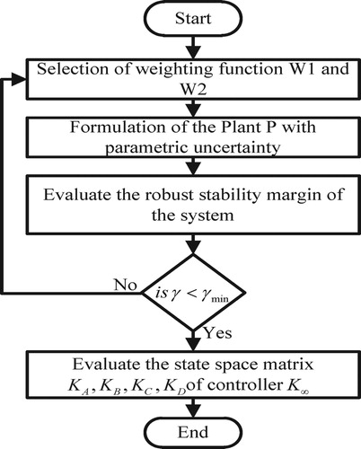
In this section, H∞-based centralized control scheme for OWF and STATCOM is discussed. The objective of centralized controller design is to optimize the controller gain subjected to parametric uncertainty and exogenous input. Loop-shaping H∞ controllers have the ability to stabilize the control parameter under parametric uncertainty and external disturbances. The undertaken steps enumerating the controller design are as follows:
Parametric uncertainty modelling of the studied system.
State space modelling of the closed loop plant with parametric uncertainty and exogenous input.
Formulation of optimal H∞ controller for the studied system.
3.1. Parametric uncertainty modelling
The parameters of offshore wind generator, marine current generator and STATCOM are time varying due to current harmonics, unbalance current or voltage distortion. Thus, variation in parameters is considered as parametric uncertainty. Its poses a challenge in the controller design which need to be addressed adequately. It consists of a nominal part plus uncertain or variable part. i.e. ,
,
,
,
,
,
.
Figure (a) shows the schematic representation of state space of studied system consisting of nominal parameters and uncertain parameters. Consequently, Figure (b) represents the frequency response of control signal under parametric variations. The bold signal is obtained with a nominal parameter and the remaining is obtained with uncertainty in parameters of the hybrid system. Its shows the impact of parametric uncertainty on the control signal and it is plotted between the control parameters, vds to idr and vqs to iqr. The fundamental frequency has been taken for the plot with the 20% of parametric uncertainty in the system.
Figure 2. (a) Schematic state space model of studied system (b) Effect of parametric uncertainty on control signal.
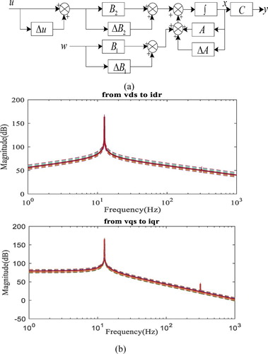
It is seen that the frequency characteristic of control signal have a range of variation with an uncertain model. This represents the effect of parametric uncertainty over the control signal. Therefore, it is considered in the controller design of studied system.
3.2. State space formulation of uncertain system
The state space structure of the studied system with uncertainty is described as
(24)
(24) where
is the state matrix of the studied system with parametric uncertainty (
), similarly
,
. “x” represents state vector.
,
and
are the control input, exogenous input, and controlled output of the studied system, respectively. The state space equations of the entire plants with parametric uncertainty are defined as
The vector of state Equation (24) is defined as
3.3. H∞ control structure formulation
The basic structure of H∞ controller has two control inputs: “W” as an exogenous input and u as a controlled input, two control outputs : “z” is the error signal and y is the observed output available for feedback. The design of proposed H∞ loop-shaping controller is based on N-Δ control structure. The typical description of N-Δ control structure is shown in Figure , which consists of uncertain part plus real system.
Figure 3. H-∞ control structure of shaped plant.
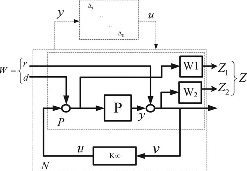
Figure 4. Flow chart.
Here is the reference signal,
is the exogenous disturbance, w = [r, d] that satisfied
. The parametric perturbation of uncertainty present in the original system are transformed in a block diagonal matrix defined as
. Where
is defined as diag
that includes
,
,
,
,
…
.
satisfied
. The input voltage of
is
and the output vector is
. The perturbed plant is shaped with two weighting functions W1 and W2 which are defined as pre- and post-compensator, respectively. The weighting function controlled the output Z1 and Z2. The block that included the controlled system with weighting function is marked as
.
The closed loop plant with controller
is marked as
.
The design of weighting function in controller as a filter shapes the uncertain perturbation of controller outputs and inputs. The sensitivity function of controller is defined as
(25)
(25)
The weighting functions are designed such as they regulate the bandwidth and fundamental frequency component of controller outputs and inputs of control law. Generally, the W1is designed as a high-pass filter, and W2 is designed as a low-pass filter, the typical function of weighting functions is given as
(26)
(26) where A is the low frequency gain of
and M is the high frequency gain of
. The optimal controller, based on H∞ loop-shaping, is bound by H∞ norms given in Equation (21), which guaranteed the robustness and stability of the optimal controller.
(27)
(27)
Therefore, the necessary and sufficient condition for designing robust controller K can be expressed as
(28)
(28)
The controller K follows the H∞ norm and the gain obtained by the controller is less than the stability margin , which ensures the robustness of the controller and stability of the system, thus the robust controller K can be realized. Therefore, the gain optimization can be formulated as
(29)
(29)
The optimal controller has been evaluated with H∞ norms to ensure the robustness of the proposed controller. The flow chart is given in Figure .
3.4. Performance measures of the proposed controller
Performance measures of the proposed controller are evaluated in terms of integral squared error (ISE), integral time squared error (ITSE), integral absolute error (IAE) and integral time-weighted absolute error (ITAE) of power signal, as mentioned in Table . It indicates the significant improvement in the power oscillations damping with the proposed controller. Hence, it ensures the robustness of the proposed controller.
Table 1. Performance indices.
4. Simulation results
In this section, OWF and MCF comprising STATCOM and BFCL are simulated and analysed with the proposed controller under dynamic and transient conditions. Different case studies are generated to evaluate the performance and efficacy of the proposed controller for minimizing the power oscillation and voltage deviation of the integrated hybrid system. Furthermore, Eigen values and participation factors are calculated to ensure the stability of the studied system. The modelling and simulation has been performed in the RTDS environment. Three different case studies have been generated to examine the efficacy of the proposed controller.
Case 1: The stochastic wind and marine current speed have been applied to the studied system, as shown in Figure (c). The response of the hybrid system, consisting of STATCOM and BFCL, has been recorded in terms of active and reactive power of the OWF and MCF, as shown in Figure (a–d). The response of the proposed controller is achieved and compared with a conventional PI controller to examine the efficacy of the proposed controller in dynamic scenarios, the speed of the wind and marine current is stochastic in nature. The simulation results suggest that the proposed controller significantly enhanced the power oscillations damping characteristic of the studied system and damped out the oscillations due to stochastic wind and marine current speed smother and faster, while it will remain oscillating with the conventional controller. Furthermore, robust H∞ controller has reduced overshoot and settling time. The corresponding active and reactive power of MCF is shown in Figures (c,d). It reflects a similar improvement in the dynamic response of the MCF. Thus, the proposed controller enhanced power oscillation damping characteristic and ensured the dynamic stability of the studied system.
Figure 5. Under dynamic conditions (a) Active power of OWF, (b) reactive power of OWF, (c) active power of MCF, (d) reactive power of MCF.
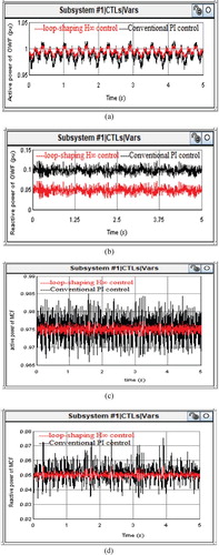
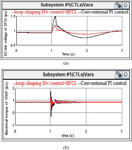
Figure 6. Under dynamic conditions (a) DC-link voltage of DFIG (b) Electrical torque of OWF (c) Dynamic speed of offshore wind.
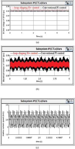
Corresponding DC link voltage of DFIG-based OWF and electrical torque angle of offshore wind generator are shown in Figure (a,b), respectively. From simulation results, we observed that the proposed controller of a hybrid system consisting of STATCOM is able to stabilize DC-link voltage and minimize the oscillation of electrical torque angle of the generator faster and smoother. Furthermore, the oscillation damping characteristic is enhanced with the proposed controller of the STATCOM.
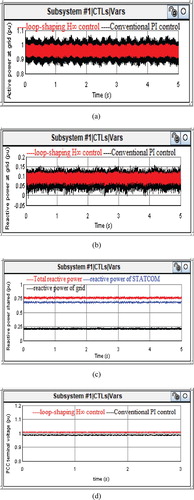
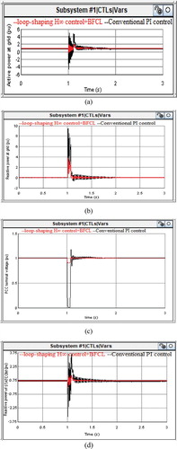
The corresponding active and reactive power export to grid is shown in Figure (a,b), respectively. It suggested that the active and reactive power oscillation at grid is less compared to the generator terminal and the damping characteristic is faster and smoother with the proposed controller at grid terminal. The reactive power drawn from the grid is less because STATCOM is connected at PCC. The reactive power shared by grid, DFIG and STATCOM is shown in Figure (c), it suggests that the STATCOM shared the maximum reactive power requirement of system which is able to stabilize the terminal voltage by locally supporting the reactive power to MCF and the local loads connected to a hybrid system. The corresponding PCC voltage is shown in Figure (d), it suggests that the proposed controller regulates the PCC terminal voltage due to the fast control action of STATCOM controller, which supplied the required reactive power at PCC. Thus, STATCOM with the proposed controller improves the damping characteristic and stability of the hybrid system.
Figure 7. Under dynamic conditions (a) active power at grid (b) reactive power at grid (c) Reactive power share of STATCOM and grid (d) PCC terminal voltage.
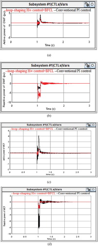
Case 2: Transient scenario: To examine the efficacy of the proposed controller and consolidated application of STATCOM and BFCL, the performance of the studied system has been evaluated under transient/fault condition by creating a fault at point F1 at t = 1sec for 0.1 sec. The response of the hybrid system is recorded and compared with the conventional PI controller with the consolidated application of the STATCOM and BFCL. The wind and marine current speed are taken constants for transient response because the duration of fault is too small and slow dynamics of turbines does not change significantly during faults. The corresponding active and reactive power of OWF and MCF is shown in Figure (a,d), respectively. Simulation results show the damping characteristics of the BFCL during faults. It provides high impedance in a fault condition and power oscillation faster and smother compared to the conventional PI controller. Furthermore, in the reactive power, a requirement during fault is significantly reduced due to the incorporation of BFCL, which helps the machine to maintain the angular stability.
Figure 8. Under transient conditions (fault at t = 1s for 0.1s) (a) active power of OWF (b) reactive power of OWF (c) active power of MCF (d) reactive power of MCF.
Correspondingly, DC-link voltage and electrical toque angle of offshore wind generator are shown in Figure (a,b), respectively. The DC-link voltage of the DFIG-based OWF is significantly improved in the presence of BFCL and STATCOM with the proposed controller due to current limiting by BFCL and reactive power support through STATCOM during faults, corresponding electrical torque oscillation damping of the generator is significantly improved with consolidated application of STATCOM and BFCL.
Figure 9. Under transient conditions (fault at t = 1s for 0.1s) (a) DC-link voltage of DFIG (b) Electrical torque of OWF.
Corresponding active and reactive power at grid are shown in Figure (a,b), while the PCC voltage and reactive power support from STATCOM are shown in Figure (c,d), respectively. Simulations results suggest that the proposed controller of STATCOM offers better damping characteristic to grid power in the presence of BFCL. Similarly, in the presence of STATCOM and BFCL, the reactive power drawn from the grid is significantly reduced which helps the voltage stability during and after the faults. The significant reduction in voltage fluctuation has been achieved in Figure (c) through consolidated application of STATCOM and BFCL. Thus, the proposed controller of studied system with STATCOM and BFCL ensures overall stability and reliability of the hybrid system.
Figure 10. Under transient conditions (fault at t = 1s for 0.1s) (a) Active power at grid (b) Reactive power at grid (c) PCC terminal voltage (d) Reactive power of STATCOM.
Case 3: Frequency-domain characteristic: the frequency domain response of the integrated system is evaluated using Eigen values and participation factors. It ensures the small signal stability of studied system in steady-state operation. The Eigen values are derived for the linearized state space model of the hybrid system in nominal operating point by the following question
(29)
(29) where λ is the Eigen value and A is the system matrix of the augmented plant and I is the identity matrix. The obtained Eigen values are listed in Table . It shows the efficacy of the proposed controller and suggests that the stability and robustness of the studied system has been significantly enhanced with the H∞ loop-shaping-based proposed controller. All the system parameters used in this study has been shown in Table .
Table 2. Eigen values of the studied system.
Table 3. System parameters.
5. Conclusion
This paper presents the stability improvement of grid interactive OWF and MCF using STATCOM and BFCL. A robust H∞ loop-shaping-based controller is designed under parametric uncertainty to enhance the controller performance and enhance the power oscillations damping characteristic, voltage stability and reactive power support. STATCOM and BFCL have consolidated their application for suitable enhancement of power oscillation damping and stability margin of the studied system. The performance of the proposed controller with STATCOM and BFCL was evaluated under dynamic and transient conditions in RTDS platform. Furthermore, Eigen values have been calculated to ensure the small signal stability of the proposed controller. The simulation results show the efficacy of the proposed controller and ensure the significant improvement in the oscillation damping and voltage stability margin with consolidated simultaneous application of STATCOM and BFCL.
Disclosure statement
No potential conflict of interest was reported by the author(s).
References
- Benelghali S, Benbouzid MEH, Charpentier JF. Marine tidal current electric power generation technology: state of the art and current status. Proceedings of IEEE International Electric Machines & Drives Conference; Antalya, Turkey; 2007. p. 1407–1412.
- Wang L, Truong DN. Stability enhancement of DFIG-based offshore wind farm fed to a multi-machine system using a STATCOM. IEEE Trans Power Syst. 2013;28(3):2882–2889.
- Bu SQ, Du W, Wang HF, et al. Probabilistic analysis of small-signal stability of large-scale power systems as affected by penetration of wind generation. IEEE Trans Power Syst. 2012;27(2):762–770.
- Mohseni M, Islam SM. Review of international grid codes for wind power integration: diversity, technology and a case for global standard. Renew Sustain Energy Rev. 2012;16(6):3876–3890.
- Sullivan DL, O'Dalton G, Lewis AW. Regulatory, technical and financial challenges in the grid connection of wave energy devices. IET Renew Power Gener. 2010;4(6):555–567.
- Jabr HM, Kar NC. Effects of main and leakage flux saturation on the transient performances of doubly-fed wind driven induction generator. Electr Power Syst Res. 2007;77(8):1019–1027.
- Mojallal A, Lotfifard S. DFIG wind generators fault diagnosis considering parameter and measurement uncertainties. IEEE Trans Sustain Energy. 2018;9(2):792–704.
- Wang L, Truong D. Stability enhancement of DFIG-based offshore wind farm fed to a multi machine system using a STATCOM. IEEE Trans Power Syst. 2013;28(3):2882–2889.
- Kuang H, Zhang S, Zeng L, et al. Stability and power quality improvement of wind power integrated system using STATCOM-PSS control. J Power Supply. 2015;13(3):100–106.
- Farias MF, Battaiotto PE, Cendoya MG. Wind farm to weak-grid connection using UPQC custom power device. IEEE International Conference on Industrial Technology, Vina del Mar; 2010. p. 1745–1750.
- Manuela Monteiro Pereira R, Manuel Machado F, Maciel BF. Comparative study of STATCOM and SVC performance on dynamic voltage collapse of an electric power system with wind generation. IEEE Latin Am Trans. 2014;12(2):138–145.
- Nasr-Azadani E, Canizares CA, Olivares DE, et al. Stability analysis of unbalanced distribution systems with synchronous machine and DFIG based distributed generators. IEEE Trans Smart Grid. 2014;5(5):2326–2338.
- Nian H, Song Y. Optimised parameter design of proportional integral and resonant current regulator for doubly fed induction generator during grid voltage distortion. IET Renew Power Gener. 2014;8(3):299–313.
- Chattopadhyay R, De A, Bhattacharya S. Comparison of PR controller and damped PR controller for grid current control of LCL filter based gridtied inverter under frequency variation and grid distortion. IEEE Energy Conversion Congress and Exposition (ECCE); Pittsburgh (PA), USA; 2014. p. 3634–3641.
- Damousis IG, Alexiadis MC, Theocharis JB, et al. A fuzzy model for wind speed prediction and power generation in wind parks using spatial correlation. IEEE Trans Energy Convers. 2004;19(2):352–361.
- Corradini ML, Ippoliti G, Orlando G. Robust control of variable-speed wind turbines based on an aerodynamic torque observer. IEEE Trans Control Syst Technol. 2013;21(4):1199–1206.
- Hu J, Zhu J, Dorrell DG. Predictive direct power control of doubly fed induction generators under unbalanced grid voltage conditions for power quality improvement. IEEE Trans Sustain Energy. 2015;6(3):943–950.
- Susperregui A, Xu L, Martinez MI, et al. Sliding-mode control of a wind turbine-driven double-fed induction generator under non-ideal grid voltages. IET Renew Power Gener. 2013;7(4):370–379.
- Kamal E, Aitouche A, Ghorbani R, et al. Robust fuzzy fault-tolerant control of wind energy conversion systems subject to sensor faults. IEEE Trans Sustain Energy. 2012;3(2):231–241.
- da Costa JP, Pinheiro H, Degner T, et al. Robust controller for DFIGs of grid-connected wind turbines. IEEE Trans Ind Electron. 2011;58(9):4023–4038.
- Nian H, Cheng P, Zhu ZQ. Coordinated direct power control of DFIG system without phase-locked loop under unbalanced grid voltage conditions. IEEE Trans Power Electron. 2016;31(4):2905–2918.
- Narendra Babu P, Peesapati R, Panda G. An adaptive differentiation frequency based advanced reference current generator in grid-tied PV applications. IEEE J Emerg Sel Top Power Electron. 2019. DOI:10.1109/JESTPE.2019.2933140.
- Kumar VN, Narendra Babu P, Kiranmayi R, et al. Improved power quality in a solar PV plant integrated utility grid by employing a novel adaptive current regulator. IEEE Syst J. 2019. DOI:10.1109/JSYST.2019.2958819.
- Narendra Babu P, Guerrero JM, Siano P, et al. An improved adaptive control strategy in grid-tied PV system with active power filter for power quality enhancement. IEEE Syst J. 2020. DOI:10.1109/JSYST.2020.2985164.
- Narendra Babu P, Chitti Babu B, Peesapati R, et al. An optimal current control scheme in grid-tied hybrid energy system with active power filter for harmonic mitigation. Int Trans Electr Energy Syst. 2020;30(3):1–21.
- Gryning MPS, Wu Q, Blanke M, et al. Wind turbine inverter robust loop-shaping control subject to grid interaction effects. IEEE Trans Sustain Energy. 2016;7(1):41–50.
- Wang Y, Wu Q, Gong W, et al. H∞ robust current control for DFIG based wind turbine subject to grid voltage distortions. IEEE Trans Sustain Energy. 2017;8(2):816–825.
- Li YW, Vilathgamuwa DM, Blaabjerg F, et al. A robust control scheme for medium-voltage-level DVR implementation. IEEE Trans Ind Electron. 2007;54(4):2249–2261.
- Gong W, Hu S, Shan M, et al. Robust current control design of a three phase voltage source converter. J Mod Power Syst Clean Energy. 2014;2:16–22.
- Zhou Z, Scuiller F, Charpentier JF, et al. Power smoothing control in a grid-connected marine current turbine system for compensating swell effect. IEEE Trans Sustain Energy. 2013;4(3):816–826.
- Rashid G, Ali MH. Transient stability enhancement of doubly fed induction machine-based wind generator by bridge-type fault current limiter. IEEE Trans Energy Convers. 2015;30(3):939–947.