
 ?Mathematical formulae have been encoded as MathML and are displayed in this HTML version using MathJax in order to improve their display. Uncheck the box to turn MathJax off. This feature requires Javascript. Click on a formula to zoom.
Abstract
This paper proposed a modified evolutionary technique formed by the hybridization of the bee colony technique and Nelder–Mead Simplex search technique to optimize the coefficients of Quadrature Mirror Filter (QMF). The performance of QMF can be evaluated in terms of error in the pass-band, stop-band and measure of ripple. A modified objective function is designed in this work, expressed as a weighted sum of errors in the pass-band, stop-band and measure of ripple. A modified objective function is minimized by using the proposed technique. The results obtained from the proposed technique are compared with the previously reported evolutionary optimization techniques based on QMF design. A significant improvement in various performance attributes has been attained compared to earlier reported QMF bank design techniques.
1. Introduction
The design of QMF bank received the attention due to their importance in the numerous applications of digital signal processing. In signal processing systems, QMF bank provides number of advantages such as removal of aliasing distortion, wider bandwidth and lower bit rates without degrading quality of output signal. Because of these advantages, QMF bank is used in multi-tone modulation systems [Citation1], sub band coding of speech [Citation2], analog to digital conversion [Citation3], image processing [Citation4], multiplexers [Citation5], two-dimensional short time spectral analysis [Citation6], design of wavelet bases [Citation7, Citation8], antenna system [Citation9], biomedical signal processing [Citation10], wireless communication for noise cancellation [Citation11] and wide-band beam-forming forsonar [Citation12].
Over the last decade, numerous optimization techniques have been proposed for QMF design [Citation12–19]. Traditionally, classical techniques were used for QMF bank design such as least-squares [Citation20, Citation21], weighted least square [Citation12, Citation14]. WLS technique introduced by Chen and Lee [Citation14] uses linearization of a non-linear design problem to obtain optimal filter coefficients. Though classical techniques were able to design QMF bank, they tend to stuck into local minima. Swarm inspired evolutionary optimization techniques, which have better performance than classical techniques, have been recently used by many researchers for QMF bank design [Citation2, Citation15, Citation22–24]. Ant colony optimization [Citation15], Differential evolution (DE) technique [Citation2], Join adaptive differential evolution (JADE) technique [Citation2], Particle swarm optimization (PSO) [Citation23, Citation24] and bee colony technique (BCT) [Citation22] are used to design two channel QMF bank.
In this work, an improved BCT is used by hybridization of two techniques, i.e. BCT technique with Nelder–Mead Simple Search (NMSS) named as hybrid BCT (HBCT) technique to improve QMF design. BCT technique is an adjustable and powerful technique than earlier used swarm intelligence techniques [Citation25], because it is inspired by the natural phenomenon and requires only one parameter to control its operation. Its implementation is easy because of having a natural search behaviour [Citation26]. It is used in number of applications such as benchmarking optimization [Citation27], scheduling application [Citation28], clustering and mining application [Citation29]. Agrawal et al. [Citation22] used the BCT technique for QMF banks design using a weighted sum of the objective function pass-band error, stop-band error, edge attenuation and first side lobe attenuation at stop-band. However, this design needs improvement to minimize reconstruction error and filter characteristics of QMF bank.
Nelder and Mead introduce NMSS in 1965 [Citation30]. It solves the classical unconstrained optimization problem, simple, easy to adapt and fast in achieving the final result. However, it generally gets trapped into local minima.
The combination of BCT and NMSS utilizes the capabilities of both techniques and avoids their individual problems. A novel objective function is formulated by using a single constant multiplier for pass-band, stop-band and measure of ripple. This constant multiplier does not require to change for filters of different order as it provides a better result for the same value of K
The manuscript contains five sections. The first section provides the introduction of QMF bank and gives an overview of the design problem. Section 2 provides the formulation of the QMF bank design. Section 3 describes the BCT technique and proposed HBCT technique. Section 4 analyses the results of the designed filter bank and compares with the available results of state-of-art methods. The last section provides the outcomes of this research and references.
2. Formulation of QMF bank design as an optimization problem
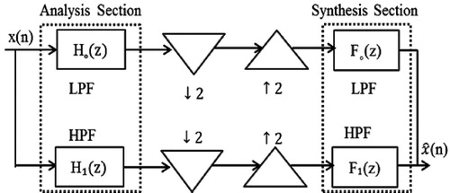
A digital filter consists of two sections, i.e. analysis section and synthesis section as shown in Figure . The input signal is split into two sub-bands, which is filtered by Low Pass Filter (LPF)
and High Pass Filter (HPF)
, and down-sampled by a factor of 2 in the analysis section. These resulting sub-band signals are up-sampled by a factor of 2 and filtered by LPF
and HPF
in the synthesis section. The resulting sub-band signals are recombined, and reconstructed output signal
is obtained. Ideally, these reconstructed output signals must be an accurate copy of the input signal. However, practically it differs from the input signal because some distortion is introduced within the reconstructed output [Citation31, Citation32]. The frequency response of (Figure ) can be written by using Z-transform [Citation18, Citation31] as
(1)
(1) where
is the distortion transfer function and it is defined as
(2)
(2) and
is the aliasing transfer function and it is defined as
(3)
(3) To reduce aliasing distortion(AD), the synthesis filters are designed in the form of analysis filters such that:
(4)
(4) The aliasing free realization can be accomplished if the transfer function of the system is a function of low-pass filter of the analysis section, which can be represented by the equation:
(5)
(5) and
(6)
(6) For phase distortion (PD) elimination, in QMF banks transfer function
used the linear phase because prototype filter
has linear phase. For gratifying the linear phase [Citation31], Impulse response
of the FIR filter having length N must be a mirror image of
(7)
(7) and discrete Fourier transform of
is
(8)
(8) where
shows the linear phase and
has a zero phase frequency response of discrete Fourier transform.
is represented as
(9)
(9) For obtaining frequency response, putting the Equation (Equation8
(8)
(8) ) into Equation (Equation5
(5)
(5) ) then following equation is represented as:
(10)
(10) If N is even, then it is the perfect reconstruction condition then Equation (Equation11
(11)
(11) ) can be defined by the following equation [Citation31]:
(11)
(11) where k is a constant. If N is odd, then
at
causing intense AMD at the quadrature frequency.
Figure 1. The process of two channel quadrature mirror filter bank.
For reducing AMD, a number of objective functions have been represented for designing QMF bank [Citation22]. In [Citation33], objective function has been formulated by using α as weighting function
(12)
(12) where
represents the total error and
is the error stop band of
. In [Citation18], objective function is represented as the weighted sum
(13)
(13) here
,
and β are the constants and
represents the pass-band error,
is the stop-band error and
is the transition error of the filter bank transfer function at
. In this work, an novel objective function is used which require only one constant weighting parameter K.
(14)
(14)
and
are calculated as follows:
(15)
(15) where
is the measure of ripple expressed in dB.
(16)
(16)
(17)
(17)
3. Hybrid bee colony technique (HBCT)
3.1. Description of BCT
BCT technique was discovered by Karaboga [Citation5, Citation29] based on information sharing behaviour of honey bees. In BCT, for the optimization problem, the position of bees positions is represented by a number of the employed bees. Initially, employed bees positions are generated. After that, the population of bees repeats the cycles of BCT. If the quantity of the new bees positions is higher than the old bees positions, then bees memorize the new position and remove the previous one. Employed bees complete the whole search process. After completing the task, they share the source's position with the onlooker on the hive then all employed bee chooses a bees positions according to the nectar quantity. The scout identifies the position of abandoned bees positions and replaces it with a new beespositions.
Let represent the
solution, where n is the problem size. In this work, size is equal to half of the order of prototype filter. Each employed bee
generates a new solution
near of its present position.
(18)
(18) where
of
is a randomly chosen bee location
is a random chosen index from the set
, and
is a random number within
. After generating the new solution
, its fitness is calculated and greedy selection is applied. If the fitness value of
is improved over
, then upgrade
with
; else retain
as it is. After complete the searching task; Onlooker bee chooses a bees positions provided by sharing the information from the employed bee with a probability based on roulette wheel selection related to its nectar amount.
(19)
(19) where
is the fitness value of the ith solution. From Equation (Equation19
(19)
(19) ) for a solution having higher fitness, the probability will be high. If a position does not improve in a predefined limit of cycles, that particular position is discarded. Assuming discarded bees positions location is
, then, previous bees positions to be replaced with new source position with as ith solution as
(20)
(20) where
is a random number within limits
, and
are lower and upper boundaries of the ith dimension, respectively.
3.2. Description of NMSS
NMSS technique is a direct search technique designed for non-linear optimization problems [Citation30]. In this technique, an N-dimensional simplex is initialized in variable space with N + 1 vertices, i.e. it is a triangle for a two-dimensional problem and tetrahedron for a three-dimensional problem. The NMSS technique's operation can be explained using four basic transformation steps, i.e. reflection, expansion, contraction and shrinkage. The steps involved in the execution of NMSS are detailed below:
Initialization:The coefficients of all four transformation, i.e
for reflection coefficient,
Ordering: According to function values, the vertices of simplex are ordering in ascending order. If
Simplex Transformations: The simplex transformations are performed for a predefined number of iterations until the termination criterion is met. The current iteration begins by removing the vertex with the highest function value
Expansion: If
Reflection: If
Contraction: This operation is executed if
Shrinkage: Shrinkage is carried out by replacing all points except
Termination: In this step of NMSS, either one new point replaces
3.3. Need of hybridization
As compared to other metaheuristic techniques, BCT technique requires only one control parameter and has a higher probability of achieving globally optima. However, BCT has some limitations such as lack of secondary information, requires new fitness tests, increase the possibility of losing relevant information, slowdown in sequential processing, especially in the vicinity of the final solution, thus leading to high computational cost. Although NMSS technique is simple, fast convergence, low execution time, required few control parameters, frequently gets trapped into local optima, and its convergence is excessively sensitive to initial seed value of variables [Citation26]. The individual drawbacks of local search and an evolutionary technique can be excluded by employing the local search technique followed by the convergence of the evolutionary technique [Citation34]. Unlike other local search techniques, NMSS is a gradient-free technique that doesn't need the calculation of derivatives as well as the number of function evaluations needed per iteration is comparatively low.
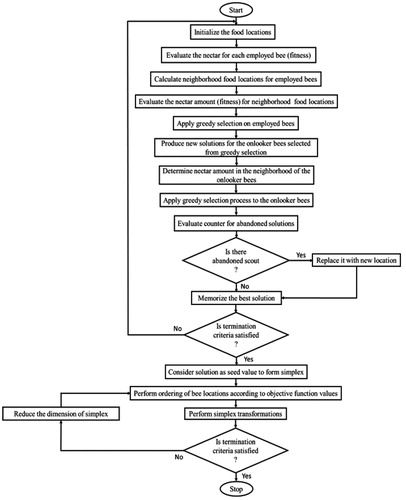
Motivation by this, BCT is hybridized with simplex search based Nelder–Mead technique, which is termed as hybridized BCT (HBCT). The combination of BCT and NMSS can provide the advantages of both the algorithm, i.e. a higher probability of global convergence (BCT) and faster execution (NMSS) while discarding their limitations. In this work, the simplex of NMSS is initialized with points acquired from the last iteration of the BCT technique, i.e. final position of the bees. The filter coefficients get updated by employed the operators of NMSS to the initial simplex. The main steps of the HBCT can be explained with the help of a flow chart as shown inFigure .
Figure 2. Flow chart of HBCT technique.
4. Result and discussion
This section presents the results of the proposed technique for QMF design. The performance is evaluated in terms of prototype filter parameters, i.e. mean square error at pass band and stop band, first side lobe, edge
attenuation at stop-band, measure of ripple, and reconstruction error. Three case studies of a prototype filter have been considered. The input signal in all the cases is a random signal. The results of the proposed technique are compared with other techniques reported in the literature [Citation18, Citation24, Citation35, Citation36].
In order to select the parameters of the techniques, various test cycles were executed for both Nelder–Mead and BCT. For BCT parameters, scout bee limit from 20 to 40 while colony size varied from 20 to 100. For Nelder–Mead, the variation for the selection of control parameters is: . Based on the results of the test cycles in BCT, scout limit and the colony size are set as 30 and 50 respectively with variable upper bound and lower bound=
. For the second technique, i.e. Nelder–Mead, the values of control parameters
are fixed at 1.8, 0.6 and
BCT is executed for iteration cycles= 200 and Nelder mead for iteration =100. The weighting parameter K is taken as 0.5.
Case study 1. Consider a prototype filter of length , pass-band and stop-band frequency is
,
. HBCT technique is executed and the 48 optimal filter coefficients
are obtained for
as depicted in Table
Table 1. The coefficients of prototype filter after optimization (N = 48).
The normalized magnitude response of analysis filters and
are shown in Figure in which frequencies are normalized from
to
. The parameters obtained from the analysis are: measure of ripple
dB, pass band error
, stop band error
, edge attenuation at stop-band
dB, first side lobe attenuation at stop band
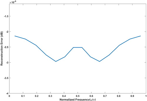
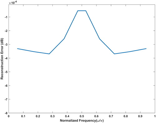
dB. Designed filter bank show small reconstruction error (Figure ). The maximum reconstruction error obtained using proposed technique is
.
Figure 3. Normalized magnitude response of the analysis filters for N = 48.
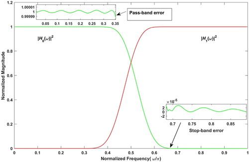
Figure 4. Reconstruction error for filter bank designed using prototype filter of order N = 48.
The designed QMF bank is compared with existing algorithms in Table . It can be observed from Table that the proposed technique outperforms other reported techniques.
Case study 2. Consider a prototype filter of length , pass-band and stop-band frequency is
,
. HBCT technique is executed and the 32 optimal filter coefficients
are obtained for
as depicted in Table .
Table 2. The coefficients of prototype filter after optimization (N = 32).
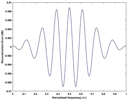
The magnitude response of analysis filters and
with normalized frequencies is shown in Figure . The resulting parameters obtained from the significant analysis are: measure of ripple
in dB
, Pass band error
, Stop band error
, edge attenuation at stop-band
, first side lobe attenuation
dB. Designed filter bank exhibits very small reconstruction error. Maximum reconstruction error in the designed filter bank is
.
Figure 5. Normalized amplitude response of analysis filters for N = 32.
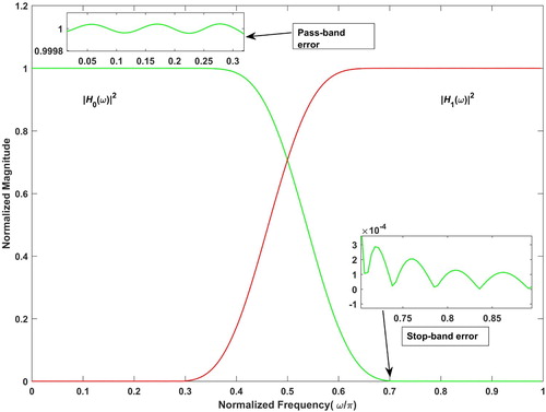
Figure 6. Reconstruction error.
To evaluate the performance of the proposed technique with respect to other reported techniques [Citation2, Citation14, Citation18, Citation19, Citation22–24], results obtained have been compared with other techniques which is represented in Table . It can be observed from Table that the proposed HBCT technique outperforms for all the above five mentioned parameters.
Case study 3. Consider a prototype filter of length , pass-band and stop-band frequency is
,
. HBCT technique is executed for the 32 optimal filter coefficients
of the
as depicted in Table .
Table 3. The coefficients of prototype filter after optimization (N = 24).
Table 4. Comparison of proposed technique with existing optimization techniques for N = 48.
The normalized magnitude response of analysis filters and
with normalized frequencies, are shown in Figure . The resulting parameters obtained from the significant analysis are: measure of ripple
in dB
, Pass band error
, Stop band error
, edge attenuation at stop-band
, first side lobe attenuation
. Designed filter bank exhibits very small reconstruction error. Maximum reconstruction error in the designed filter bank is
.
Figure 7. Normalized amplitude response of analysis filters for N = 24.

Figure 8. Reconstruction error.
The efficacy of the proposed technique is evaluated by comparing it with other reported optimization techniques [Citation18, Citation22, Citation24, Citation37] of QMF design. The results obtained have been compared as shown in Table . It can be analysed from Table that the HBCT outperforms in terms of ,
,
, and
then all other reported techniques, however it attains third best for
.
Table 5. Comparison of proposed technique with existing optimization techniques for N = 32.
Table 6. Comparison of proposed technique with existing optimization techniques for N = 24.
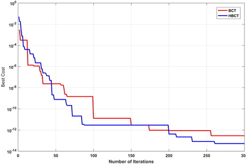
Lastly, the proposed HBCT is compared with BCT to check the convergence speed as shown in Figure . Both techniques are executed for iteration cycle T = 300. It can be observed from Figure that HBCT converges faster as compared to BCT required less number of iterations. Therefore, the insertion of proficient local search by NMSS technique within the framework of the traditional BCT technique provides fast convergence and better results as compared to conventional ABC.
Figure 9. Convergence plot for proposed HBCT and BCT techniques.
5. Conclusion
In this paper, the design of a two-channel QMF bank using HBCT is proposed. This technique utilizes the advantages of BCT and NMSS techniques to avoid the problem of converging to a local optimum solution. The proposed technique has been tested on three case studies of QMF design using a novel weighted objective function expressed as a sum of pass-band error, stop-band error, and measure of ripple using a single constant multiplier K. The parameters obtained from the proposed technique have been compared with existing QMF design techniques. The results show the proposed technique outperforms earlier reported techniques for QMF design.
Disclosure statement
No potential conflict of interest was reported by the author(s).
References
- Vetterli M. Multi-dimensional sub-band coding: some theory and algorithms. Signal Processing. 1984;6(2):97–112.
- Ghosh P, Das S, Zafar H. Adaptive-differential-evolution-based design of two-channel quadrature mirror filter banks for sub-band coding and data transmission. IEEE Trans Syst Man Cybernetics, Part C Appl Rev. 2012;42(6):1613–1623.
- Petraglia A, Mitra SK. High speed A/D conversion using QMF banks. In: IEEE International Symposium on Circuits and Systems, IEEE City: New Orleans, LA, USA. 1990. p. 2797–2800.
- Prakash R, Singh D, Pathak NP. A fusion approach to retrieve soil moisture with SAR and optical data. IEEE J Sel Top Appl Earth Obs Remote Sens. 2011;5(1):196–206.
- Manoj V, Elias E. Artificial bee colony algorithm for the design of multiplier-less nonuniform filter bank transmultiplexer. Inf Sci (NY). 2012;192:193–203.
- Wackersreuther G. On two-dimensional polyphase filter banks. IEEE Trans Acoust. 1986;34(1):192–199.
- Sablatash M. Designs and architectures of filter bank trees for spectrally efficient multi-user communications: review, modifications and extensions of wavelet packet filter bank trees. Signal Image Video Process. 2008;2(1):9–37.
- Sharma MM, Deegwal JK, Kumar A, et al. Compact planar monopole UWB antenna with quadruple band-notched characteristics. Progr Electromagn Res. 2014;47:29–36.
- Verma A, Ghugtyal B, Singh Y, et al. An optimization technique for QMF based on modified particle swarm. In: 2015 2nd International Conference on Signal Processing and Integrated Networks (SPIN), IEEE City: Noida, India. 2015. p. 666–669.
- Afonso VX, Tompkins WJ, Nguyen TQ, et al. ECG beat detection using filter banks. IEEE Trans Biomed Eng. 1999;46(2):192–202.
- Hara S, Masutani H, Matsuda T. Filter bank-based adaptive interference canceler for co-existence problem of TDMA/CDMA systems. In: Gateway to 21st Century Communications Village. VTC 1999-fall. IEEE VTS 50th Vehicular Technology Conference (cat. no. 99ch36324), IEEE City: Amsterdam, Netherlands. Vol. 3. 1999. p. 1658–1662.
- Lu WS, Xu H, Antoniou A. A new method for the design of FIR quadrature mirror-image filter banks. IEEE Trans Circuits Syst II Analog Digital Signal Process. 1998;45(7):922–926.
- Agrawal S, Sahu O. Two-channel quadrature mirror filter bank: an overview. ISRN Signal Process. 2013;2013:815619.
- Chen CK, Lee JH. Design of quadrature mirror filters with linear phase in the frequency domain. IEEE Trans Circuits Syst II Analog Digital Signal Process. 1992;39(9):593–605.
- Dorigo M, Birattari M. Ant colony optimization. New York: Springer; 2010. (Encyclopedia of Machine Learning)
- Goh CK, Lim YC, Ng CS. Improved algorithm to design weighted minimax quadrature mirror filters. In: 1996 IEEE International Symposium on Circuits and Systems. Circuits and Systems Connecting the World, IEEE City: Atlanta, GA, USA. ISCAS 96, Vol. 2. 1996. p. 381–384.
- Ho CYF, Ling BWK, Benmesbah L, et al. Two-channel linear phase FIR QMF bank minimax design via global nonconvex optimization programming. IEEE Trans Signal Process. 2010;58(8):4436–4441.
- Sahu O, Soni M, Talwar I. Marquardt optimization method to design two-channel quadrature mirror filter banks. Digit Signal Process. 2006b;16(6):870–879.
- Swaminathan K, Vaidyanathan P. Theory and design of uniform DFT, parallel, quadrature mirror filter banks. IEEE Trans Circuits Syst. 1986;33(12):1170–1191.
- Andrew L, Franques V, Jain V. Eigen design of quadrature mirror filters. IEEE Trans Circuits Syst II Analog Digital Signal Process. 1997;44(9):754–757.
- Johnston J. A filter family designed for use in quadrature mirror filter banks. In: ICASSP'80. IEEE International Conference on Acoustics, Speech, and Signal Processing, IEEE City:Boston, MA, USA. Vol. 5. 1980. p. 291–294.
- Agrawal S, Sahu OP. Artificial bee colony algorithm to design two-channel quadrature mirror filter banks. Swarm Evol Comput. 2015;21:24–31.
- Rafi S, Kumar A, Singh GK. An improved particle swarm optimization method for multirate filter bank design. J Franklin Inst. 2013;350(4):757–769.
- Upendar J, Gupta CP, Singh GK. Design of two-channel quadrature mirror filter bank using particle swarm optimization. Digit Signal Process. 2010;20(2):304–313.
- Dwivedi AK, Ghosh S, Londhe ND. Bit level FIR filter optimization using hybrid artificial bee colony algorithm. In: 2015 Annual IEEE India Conference (INDICON), IEEE City: New Delhi, India. 2015. p. 1–6.
- Dwivedi AK, Ghosh S, Londhe ND. Low-power FIR filter design using hybrid artificial bee colony algorithm with experimental validation over FPGA. Circuits Systems Signal Process. 2017;36(1):156–180.
- Zou W, Zhu Y, Chen H, et al. A clustering approach using cooperative artificial bee colony algorithm. Discrete Dyn Nat Soc. 2010;2010:459796.
- Karaboga D, Gorkemli B, Ozturk C, et al. A comprehensive survey: artificial bee colony (ABC) algorithm and applications. Artif Intell Rev. 2014;42(1):21–57.
- Karaboga D, Ozturk C. A novel clustering approach: artificial bee colony (ABC) algorithm. Appl Soft Comput. 2011;11(1):652–657.
- Nelder JA, Mead R. A simplex method for function minimization. Comput J. 1965;7(4):308–313.
- Vaidyanathan PP. Multirate digital filters, filter banks, polyphase networks, and applications: a tutorial. Proc IEEE. 1990;78(1):56–93.
- Vaidyanathan PP. Multirate systems and filter banks. Pearson Education India; 1993.
- Jain V, Crochiere R. Quadrature mirror filter design in the time domain. IEEE Trans Acoust. 1984;32(2):353–361.
- Fong CW, Asmuni H, Lam WS, et al. A novel hybrid swarm based approach for curriculum based course timetabling problem. In: 2014 IEEE Congress on Evolutionary Computation (CEC), IEEE City: Beijing, China. 2014. p. 544–550.
- Kumar A, Singh GK, Anand R. An improved method for designing quadrature mirror filter banks via unconstrained optimization. J Math Model Algorith. 2010;9(1):99–111.
- Sahu O, Soni M, Talwar I. Designing quadrature mirror filter banks using steepest descent method. J Circuits Syst Comput. 2006a;15(01):29–41.
- Kumar A, Rafi S, Singh GK. A hybrid method for designing linear-phase quadrature mirror filter bank. Digit Signal Process. 2012;22(3):453–462.