
 ?Mathematical formulae have been encoded as MathML and are displayed in this HTML version using MathJax in order to improve their display. Uncheck the box to turn MathJax off. This feature requires Javascript. Click on a formula to zoom.
Abstract
In this study, the hysteresis based direct torque control (DTC) of a three-phase induction motor was carried out experimentally. The DTC algorithm was also modelled in the hardware environment by using FPGA’s in-the-loop feature. The dSPACE DS1103 controller board was used in the experimental study and Altera DE2-115 model development board was used in the hardware modelling. Both applications had the same sample time and all of the DTC algorithm was tested within the FPGA. The hardware simulation study conducted in FPGA environment was carried out in MATLAB/Simulink environment. The experimental results were compared with the hardware simulation results obtained from FPGA. As a result of the comparison, it was shown that DTC algorithm could be realized easily in FPGA environment without experimental installation, and the obtained current, voltage and velocity graphs were similar.
1. Introduction
The high performance Alternating Current (AC) drivers developed for the controlling of induction motors that are widely used in industrial applications enable the control of the motor speed, torque or rotor position in the determined operating ranges. The control process on AC drives is performed as scalar or vector. In the scalar control method, the controlled variables are the stator voltage and stator frequency. By keeping the V/f ratio of the voltage and frequency applied to the stator as constant, the air gap flux is also kept constant; thus, it is tried to ensure that the motor generates constant torque at all speed ranges. In the regions of low and high speed where field attenuation is required, the motor exits from the constant torque region and continues to operate in the stationary power zone and thereby the motor’s torque constancy deteriorates. For this reason, scalar control method is not preferred for applications requiring precision position control. However, this method is widely used in applications that do not require high performance due to the fact that its implementation is easy and low-cost [Citation1].
In the vector control method, on the other hand, the flux and torque of the motor are controlled independently of each other as in a direct current (DC) motor. Due to their mathematical model, induction motors have a complex structure whose parameters change within time and that includes non-linear and high order differential equations. Because of this complex structure, the control of an induction motor is more difficult than the control of a DC motor. The reason of this is that there is a clamping effect between the current and flux components which constitute the torque and flux of the motor. In other words, these components constituting the torque and the flux are not independent from each other since there is no phase difference of 90° as in the DC motor. As a result of the analytical analysis on the motor model and with the development of the motor model that would eliminate this clamping effect, the vector-controlled AC drivers first started to take their place in the historical development process by a study [Citation2] of German engineer Blaschke in 1971. The vector control method is the basis of high-performance AC driver systems. The Field Oriented Control (FOC) and the DTC methods, which are among the vector control methods, are widely used today.
FOC method, proposed by Blaschke in 1971, is a rotor-field-oriented vector control method based on independent control of flux and torque by separating the stator currents of a three-phase induction motor into the flux and current components of the motor. Although it has a high dynamic response, the realization of this method requires high accuracy axial conversions, accurate estimation of the angle of the flux vector depending on the type of field orientation, measurement of the rotor speed, and use of the estimated sliding frequency and many complex calculations. This method is also very sensitive to changes in motor parameters.
On the other hand, the DTC method, proposed by Takahashi [Citation3] in 1986, is a stator-field-oriented vector control method based on the independent control of the actual flux and torque of the motor within the hysteresis band around the specified reference flux and moment. Although it has a high dynamic response, it is a simple and durable method. In this method, for feedback, it is required to obtain the stator flux and motor torque by calculating. Only the stator in the motor parameters is dependent on the stator winding resistance; therefore, it is less sensitive to parameter changes. The main purpose of both methods is to control the torque and flux of the motor independently without being affected by the parameter changes too much. In the last 20 years, many studies have been carried out especially on DTC and the controllers used within this control structure. Genetic algorithms, fuzzy logic, artificial neural networks, and neuro-fuzzy control algorithms [Citation5] have been widely used in controller designs. In addition, some studies have been successfully carried out; in the determination of parameter changes [Citation4], in obtaining the constant switching frequency [Citation6], instead of the switching table [Citation7], in determining the amplitude and angle of the reference voltage vector [Citation8], in the selection of voltage vectors [Citation9], as the speed controller [Citation10], in the torque ripple reduction and stator resistance estimation [Citation11], in the rotor speed, stator and rotor flux estimations, and as fuzzy logic based sliding mode speed controller [Citation12], and in flux and torque control [Citation3].
Motor control applications performed using FPGA have increased in recent years. Another feature of the FPGA is that it offers the opportunity to perform hardware tests of the software. In recent years, using FPGA in-the-loop (FIL) feature, the hardware testing of the software and the comparison of it with the applications have been widely performed. In reference [Citation14], a mathematical model of an induction motor was created and the control of this motor was performed. Co-simulation of the system was carried out by using Modelsim and MATLAB /Simulink. The software language was in VHDL format and it was finally brought into the condition to use in FPGA. In reference [Citation15], a high-performance control of a BLDC motor was performed. The proposed control algorithm was tested in the XSG (Xilinx System Generator) and MATLAB/Simulink environment using the FPGA produced by Xilinx Company. The success of the proposed control method was demonstrated by a real-time dynamic simulation. The Space Vector Pulse Width Modulation (SVPWM) algorithm is widely used in the control of electric motors. In reference [Citation16], the extended SVPWM control algorithm was used to control the delta inverter that drives an induction motor. The control of the induction motor was carried out using FPGA. In addition, hardware co-simulation was carried out by using XSG. It was shown that the experimental results and simulation results were similar [Citation16]. The shaft resolvers are used to determine the angular position of the motor. In order to calculate the motor angle, a hardware simulation was performed using the FPGA in-the-loop feature. It was shown that the method used in this study occupies very little place in FPGA [Citation17]. FPGAs are used in many applications in industry, except for motor control applications. Therefore, hardware simulation feature is also used in many fields. In reference [Citation18], the output powers of photovoltaic systems with different mathematical models were investigated by using XSG. Also, the total area covered within FPGA by each model was shown. In another study, a photovoltaic system and FPGA-based hardware in-the-loop simulation of the power electronics of this system were realized. Here, the voltage source inverter (VSI) was modelled as real-time, and MATLAB/Simulink simulation results and hardware in-the-loop results were compared [Citation19]. Hardware in-the-loop simulation of power converters, whose numerical control was carried out, was performed. Thus, the behaviour of the closed-loop controlled power converters was investigated before the prototype circuit was performed [Citation20]. Time delays occur in the simulation of high frequency power electronics systems. A new parallel power converter simulation was performed by using the hardware in-the-loop feature. The proposed simulation technique was tested in a traction power electronics application [Citation21]. The real-time hardware in-the-loop simulation of large-size power electronics systems with high frequency control strategy is a problem. In reference [Citation22], a new analysis method was proposed to obtain both fast and accurate results. The proposed method was presented for the traction system of an electric locomotive [Citation22]. In another study, the power system model of a fuel cell electric vehicle was carried out by using FPGA and hardware in-the-loop. Thus, the testing of the proposed model from commercial studies was performed [Citation23]. The FPGA hardware in-the-loop is also used in the analysis of power systems. Different methods are used for harmonic analysis in power systems. The harmonic estimation performed using a discrete wavelet packet transform (DWPT) is one of these methods. A power system harmonic analysis conducted using DWPT was carried out with XSG hardware co-simulation [Citation24]. In order to reduce the noise of the images in medical systems, some filtering techniques were applied with co-simulation through using MATLAB/Simulink and XSG. The performances of the filters and the areas they covered in the FPGA were compared [Citation25]. A hybrid protection system was developed for the bipolar HVDC. The performance of the proposed method was evaluated by real-time hardware simulation through using XSG and AccelDSP [Citation26]. In reference [Citation27], Space Vector Modulation-SVM, Sliding Mode Control-SMC, Model Predictive Control-MPC, Fuzzy Logic-FL, Neural Network-NN, and Genetic Algorithm-GA based improved DTC algorithms were explained. These algorithms were presented comparatively in terms of torque ripple, tracking speed, switching loss, algorithm complexity, and parameter sensitivity. In reference [Citation28], DTC control of the induction motor and its implementation in electric vehicles were explained. Reference [Citation29] presented an improved Fuzzy Logic-based DTC strategy for a Doubly Fed Induction Machine-DFIM. It was shown that this method increased the performance of the motor by reducing torque fluctuations and THD.
In this study, a hysteresis-controller-based DTC of a three-phase induction motor was carried out experimentally. Experimental study was performed with dSPACE DS1103 controller board. The motor and system parameters used in the experimental study were also used in the hardware simulation study which was carried out by using FPGA in-the-loop. For hardware simulation, Altera DE2-115 development platform and MATLAB /Simulink were used. The actual application results and the results that obtained through FPGA in-the-loop were compared.
2. Direct torque control of induction motor
DTC method is a vector control method that allows independent control of the flux and torque of the high coupled alternating current motors whose state variables have sinusoidal structure. In this method, the stator magnetic field is directed by using the stator flux and all calculations are made in the αβ stationary frame.
2.1. Flux and torque equations for direct torque control
The simplest form of the flux estimation techniques is the stator voltage model. The relation between stator voltage and stator flux in the αβ frame is given in Equation (1).
(1)
(1)
The αβ components of Equation (1) are given in Equations (2)–(3).
(2)
(2)
(3)
(3)
The stator flux is defined as the integral of the back emf voltage induced in the stator windings [Citation13] and is calculated by using the stator voltage equation given in Equation (1) as follows.
(4)
(4)
The αβ components of Equation (4) are given in Equations (5)–(6) below.
(5)
(5)
(6)
(6)
The amplitude of the stator flux generated by the αβ flux components is obtained as shown in Equation (7).
(7)
(7)
If the ohmic voltage drop at about on the stator winding resistance given in Equation (4) is neglected, Equation (8) is obtained.
(8)
(8)
As it is seen in Equation (8), the stator flux vector is the integral of the applied voltage vector
and moves in the direction of magnitude and direction of this voltage vector at the same time. Therefore, direction, speed, and magnitude of the stator flux vector are directly related to the applied voltage vectors. Depending on the stator flux vector obtained by Equation (8) and the stator currents, the motor torque are calculated as in Equation (9).
(9)
(9)
As it is seen, the instant value of the electromagnetic torque generated in a three-phase symmetric induction motor is directly proportionate to the vector multiplication of the stator flux vector and the stator current vector
. Another torque expression in terms of stator fluxes and phase currents in the stationary frame can be written as given in Equation (10).
(10)
(10)
The determination of the region of the stator flux vector is required for the selection of the voltage vectors. The angular position of the stator flux vector is obtained by the trigonometric transformation in Equation (11) via using the αβ stator flux components given in Equations (5) and (6),
(11)
(11)
Here, is the angle between the stator flux vector and the reference α-axis. Which sector the vector, whose angular position has been found, is in on the 360° circular plane is determined with Equation (12). In addition, the starting and ending points of the sectors are also determined by this Equation.
(12)
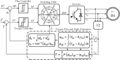
(12) where N (1,2,3,4,5,6) is sector number. Each sector has an angle of 60° determined by the position of active voltage vectors in space. The Equations (5)–(7) and (10) are known as the basic equations of the DTC method and are incorporated into the process of the flux-torque-angle prediction block within the control structure given in Figure . In Figure , the basic principle diagram of the hysteresis-based DTC method, in which the stator flux and motor torque are controlled directly by the two hysteresis controllers, is given. This method has high success because the flux and torque are directly controlled.
Figure 1. Basic principle diagram of the driver system with DTC.
2.2. Hysteresis control structure
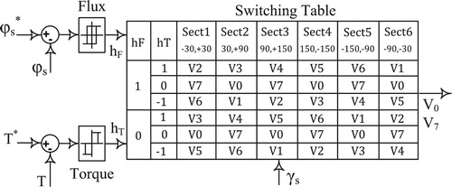
In the conventional DTC structure proposed by Takahashi [Citation6], two separate hysteresis controllers and a switching table were used for the discrete control of flux and torque, as shown in Figure . Hysteresis controllers use flux and moment errors as inputs. The estimated actual motor flux and torque, the error signals obtained after compared with the reference values are restricted such a way to remain within a hysteresis band whose limits are predetermined. As a result of this restriction, the numerical [1, 0, −1] control signals obtained at the controller outputs are used as input to the switching table depending on the positive and negative limit values of the hysteresis bands. The main tasks of the hysteresis controllers within this control structure are (i) to keep the flux and torque errors in their hysteresis bands, and (ii) to select the appropriate voltage vectors from the switching table using control signals [1, 0, −1], which are obtained depending on the flux and torque errors.
Figure 2. Overview of the hysteresis controllers and the switching table.
The total harmonic distortion in the motor currents, the inverter switching frequency, the switching losses and the torque ripples are a function of these hysteresis controller bandwidths. Since it will directly affect the dynamic behaviour of the motor, the bandwidth to be selected for both controllers should be at the most appropriate value. These bandwidths also play an important role in determining the application time of selected active and zero voltage vectors. The hysteresis controllers with constant bandwidth do not always give the best results for all speed ranges. Therefore, the bandwidths must be adjusted for different speed and load values. Generally, while two-level hysteresis controller is used for flux control, three-level hysteresis controller is used for torque control.
2.3. Experimental implementation of DTC
In the driver setup developed for experimental applications, the sampling period required for a control loop was determined as μs (fs = 20 kHz). The experimental results of the hysteresis-based control structure were taken during this sampling period.
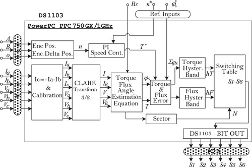
There was a PowerPC PPC750GX/1 GHz main processor and a Texas Instruments TMS320F240/20 MHz satellite processor on the DS1103 controller board where the control algorithm was performed. The block diagram for the part of the DTC algorithm performed on the main processor is given in Figure .
Figure 3. Block diagram for the control algorithm part performed within DS1103.
3. FPGA hardware in-the-loop concept
FPGAs are used in motor control applications, filtering of images and signals, and in many industrial applications. In addition, there is also the possibility to perform hardware test of the developed software and the control methods. In recent years, real-time simulations of many current applications have been carried out by using the MATLAB/Simulink software and FIL feature (hardware co-simulation) of FPGA.
3.1. Rapid hardware design tools
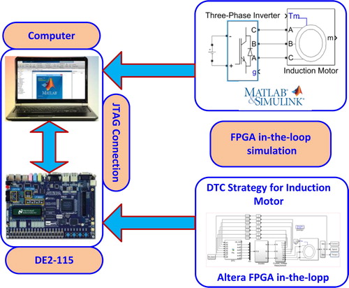
The algorithm to be simulated in real time must be performed in the MATLAB /Simulink environment with the system or other components of the system. In the next step, VHDL codes of the system desired to perform in FPGA are generated. Finally, the synthesis process is performed using the VHDL codes and the FIL feature is run. Thus, the part of the algorithm which is tested in the simulation environment in FPGA is tested in the hardware environment. The FIL feature works together with Altera FPGA and MATLAB. This study was carried out by using the FIL Altera DE2-115 model development board. This board has Altera Cyclone IV EP4CE115F29 FPGA.
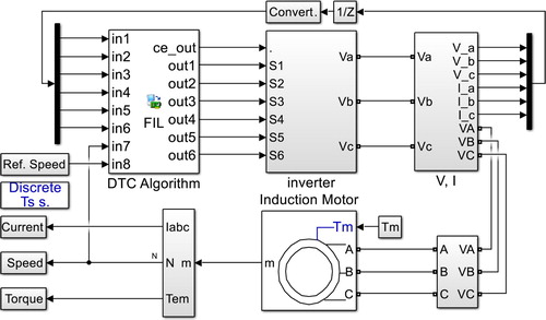
In this study, a hardware and real-time simulation of the induction motor speed control that was experimentally performed with direct torque controller, was carried out by using the FIL feature of Altera FPGA. The block diagram of the simulation is shown in Figure . After the FIL block is synthesized, the FPGA in-the-loop simulation is started. The DTC method operates within the FPGA and sends the output data to the MATLAB /Simulink environment via the JTAG communication protocol. Here, the simulation of the inverter and the motor parts are operated, and the data obtained from the motor output is sent again to the FIL block (i.e. FPGA) and these operations are repeated in each cycle. The cycle speed will be equal to the operating speed of the FPGA.
Figure 4. FPGA in-the-loop simulation block diagram
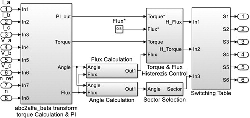
PI speed controller, αβ transformations, flux, angle, sector calculations, hysteresis bands and switching table were arranged within FPGA. In the actual application, all of these operations were performed within dSPACE.
3.2. FPGA based real-time simulation of DTC
The block containing the hysteresis controller-based DTC algorithm was primarily regulated as a fixed-point in a way that it would operate within the FPGA. The data processing speed of the used FPGA was 20 ns. This speed value is quite large for the analog input measurement speed and switching frequency value in a real system. Therefore, the necessary regulations were made so that the simulation time was to be 50 µs. After the algorithm to be simulated is synthesized and the FIL block is created, it is impossible to see inside of the block. The structure of the performed control method before synthesized with FIL is given in Figure .
Figure 5. The FIL block structure of the hysteresis controller-based DTC structure before synthesis.
Motor currents, voltages and rotor speed constitute the inputs of the DTC algorithm. The trigger signals of the inverter switching elements used as motor drivers constitute the outputs. The general simulation of the control system together with the FIL block generated by synthesizing the algorithm is given in Figure .
Figure 6. The simulation of the hysteresis controller-based DTC structure by FIL block and MATLAB /Simulink.
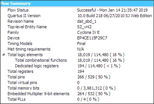
The resource utilization of the algorithms to be used or the system to be simulated by FIL is very important within the FPGA. The resource utilization in real systems should provide opportunities to modify and to develop the algorithm or to add new algorithms. Therefore, the control algorithm whose VHDL codes were derived was synthesized using the Quartus II software. Accordingly, the DTC control structure, designed to be able to use FPGA, consumed a reasonable amount of resources in the FPGA. The flow summary showing the FPGA resource utilization at the end of the synthesis is seen in Figure .
Figure 7. Flow summary seen at the end of the Quartus IIsynthesis process.
4. Comparison of experimental implementation and real-time simulation
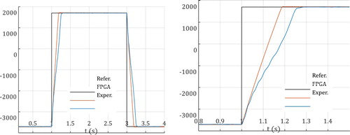
In this section, current, torque and speed graph related to the DTC method of the induction motor and obtained by means of hardware simulation in both experimental and FPGA environment are given. Experimental studies were carried out by the help of the experimental driver setup given in Figure . Hardware simulation studies were also carried out by the help of the simulation model given in Figures . In the graphs given below, the steady-state performance in unloaded condition and the transient-state response of the four-quadrant operation are examined for the induction motor controlled. In Figure a,b, the tracking performance of the motor speed is given for a square-wave reference speed of ±2700 rpm. In transient regimes of speed changes; settling time of the motor speed obtained by the experimental method is 280 ms, and settling time of the motor speed obtained by FPGA is 180 ms. In steady-state, the motor tracks the given reference properly without exceeding the given reference speed. Both speed responses are similar in terms of settling times and the difference of 100 ms is due to the fact that the experimental system is a real physical system.
Figure 8. For square-wave reference speed, motor speed obtained experimentally and with FPGA in-the-loop, (a) in the range of 0–4 s, (b) in the range of 0.8–1.6 s.
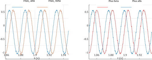
As seen in Figure a,b, the motor completed its transient-state by generating a reference torque of 6 Nm that was determined by the speed controller. Both torque responses are approximately the same in terms of behaviour. Torque ripple in the transient-state is similar for both applications, but the torque ripples in the steady-state are different in terms of amplitude. The ripple band in the torque obtained experimentally is less. Reason of this is that the motor which is a real physical system acts as a natural filter. Figure a,b show the αβ stator flux components.
Figure 9. For the square-wave reference speed, motor torque obtained experimentally and with the FPGA in-the-loop, (a) in the range of 0–4 s, (b) in the range of 0.8–1.6 s.
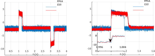
Figure 10. α/β fluxes at speed of 2700 rpm, (a) Experimental study, (b) FPGA in-the-loop.
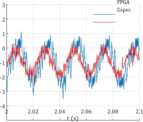
The S_phase current that is taken from the grid by the unloaded motor are comparatively shown in Figure a,b. Both currents are similar in terms of the general behaviour. Since the motor itself acts as a filter in the experimental application, the experimentally obtained motor current has a total harmonic distortion less than the motor current obtained by FPGA.
Figure 11. S_phase currents at the speed of 2700 rpm.
5. Conclusion
Hysteresis controller-based DTC method is a vector control method that allows independent control of the flux and torque of induction motors. In this study, DTC of a three-phase induction motor was experimentally performed by using the dSPACE DS1103 digital signal processing board. Hysteresis switching method was selected for the control of current and torque.
In recent years, FPGAs have come to the forefront with their hardware co-simulation feature. Altera offers hardware simulation possibility with FPGA in-the-loop feature. In the conducted experimental study, DTC algorithm was re-organized as fixed-point for FPGA environment. The validity of the study was shown by producing VHDL codes. The resource consumption of the proposed control structure in FPGA was also examined and it was shown that this structure is appropriate and usable for FPGA. Using the Altera DE2-115 platform and the FPGA in-the-loop feature, the hardware test of the control structure was performed in the MATLAB/Simulink environment.
The results of the experimental study and the results of the FPGA in-the-loop test were compared. Looking at the obtained results, it was observed that the currents, flux, torque and rotor speed of the motor were quite similar in the both methods. In addition, it was shown in this study that before experimentally performed, by using only FPGA in-the-loop hardware test feature, whether DTC or a similar motor control algorithm run or not, or control performance of it can be observed.
Disclosure statement
No potential conflict of interest was reported by the author(s).
References
- Bose BK. Modern power electronics and AC drivers. New Jersey: Prentice Hall; 2002.
- Blaschke F. A new method for the structural decoupling of AC induction machines. Conf Rec IFAC, Dusseldorf, Germany, Oct. 1971; p. 1–15.
- Takahashi I, Noguchi T. A new quick-response and high efficiency control strategy of an induction motor. IEEE Trans Ind Appl. 1986; IA-22(5):820–827.
- Zidani F, Said RN. Direct torque control of induction motor with fuzzy minimization torque ripple. J Electr Eng. 2005;56(7–8):183–188.
- Vasudevan M, Arumugam R, Paramasivam S. High-performance adaptive intelligent direct torque control schemes for induction motor drives. Serbian J Elect Eng. 2005;2(1):93–116.
- Yang JQ, Huang J. Direct torque control system for induction motors with fuzzy speed PI regulator. Proc of 2005 Int Conf Mach Learn Cyber. 2005;2:778–783.
- Jabeur-Seddik CB, Fnaiech F. DTFC and DTNFC: two intelligent techniques for induction motors torque control. ISIE’2005, Proc IEEE Int Symp Indust Electron. 2005;1:131–138.
- Gama Valdez MA, Romero D. Improvement of an induction motor drive-based direct torque control strategy using a neuro-fuzzy controller. ICEEE’2004, 1st International Conference on Electrical and Electronics Engineering; 2004. p. 439–444.
- Wei X, Chen D, Zhao C. Minimization of torque ripple of direct-torque controlled induction machines by improved discrete space vector modulation. Elsevier, Elect Power Syst Res. 2004;72(2):103–112.
- Lai YS, Lin JC. New hybrid fuzzy controller for direct torque control induction motor drives. IEEE Trans Power Electron. 2003;18(5):1211–1219.
- Rajaji L, Kumar C. Adaptive neuro-fuzzy inference systems into squirrel cage induction motor drive: modeling, control and estimation. 5th International Conference on Electrical and Computer Engineering, ICECE; 2008. p. 162–169.
- Gadoue SM, Giaouris D, Finch JW. Artificial intelligence-based speed control of DTC induction motor drives-a comparative study. Elsevier, Electric Power Syst Res. 2009;79(1):210–219.
- Trzynadlowski AM. Control of induction motors. San Diego: Academic Press; 2001.
- Kung YS, Chen SC, Lin JM, et al. FPGA-realization of a speed control IC for induction motor drive. Eng Comput (Swansea). 2016;33(1):1835–1852.
- Yadav P, Poola R, Najumudeen K. High dynamic performance of a BLDC motor with a front end converter using an FPGA based controller for electric vehicle application. Turk J Elec Eng Comp Sci. 2016;24:1636–1651.
- Alouane A, Rhouma AB, Hamouda M, et al. Efficient FPGA-based real-time implementation of an SVPWM algorithm for a delta inverter. IET Power Electron. 2018;11(9):1611–1619.
- Celikel R, Aydogmus O. A FPGA-based position calculation for shaft resolvers. Int Adv Technol Symp (IATS’17). 2017: 368–374.
- Tadrist R, Hassani A, Maamoun M, et al. Efficient FPGA implementation to estimate the maximum output power of a photovoltaic panel using Xilinx system generator. Amer J Appl Sci. 2016;13(5):522–532.
- Selvamuthukumaran R, Gupta R. Rapid prototyping of power electronics converters for photovoltaic system application using Xilinx system generator. IET Power Electron. 2014;7(9):2269–2278.
- Fernández-Álvarez A, Portela-García M, García-Valderas M, et al. HW/SW co-simulation system for enhancing hardware-in-the-loop of power converter digital controller. IEEE J Emerg Sel Top Power Electron. 2017;4(4):1779–1786.
- Liu C, Ma R, Bai H, et al. A new approach for FPGA-based real-time simulation of power electronic system with no simulation latency. Subsystem Partition Int J Elect Power Energy. 2018;99:650–658.
- Liu C, Ma R, Bai H, et al. Hybrid modeling of power electronic system for hardware-in-the-loop application. Electr Power Syst Res.2018;163:502–512.
- Ma R, Liu C, Zheng Z, et al. CPU-FPGA based real-time simulation of fuel cell electric vehicle. Energy Convers Manage. 2018;174:983–997.
- Tiwari VK, Jain SK. Hardware implementation of polyphase-decomposition-based wavelet filters for power system harmonics estimation. IEEE Trans Instrum Meas. 2016;65(7):1585–1595.
- Junior EI, Garces LM, Cabrera AJ, et al. Performance analysis of algorithms over FPGA for removing salt and pepper noise. IEEE Latin Am Trans. 2016;14(5):2120–2127.
- Liu X, Osman AH, Malik OP. Real-time implementation of a hybrid protection scheme for bipolar HVDC line using FPGA. IEEE Trans Power Deliv. 2011;26(1):101–108.
- El Ouanjli N, et al. Modern improvement techniques of direct torque control for induction motor drives-a review. Protect Cont Modern Power Syst. 2019;4(11):1–12.
- Sutikno T, Nik Idris NK, Jidin A. A review of direct torque control of induction motors for sustainable reliability and energy efficient drives. Renewable Sustain Energy Rev. 2014;32:548–558.
- El Ouanjli N, et al. Improved DTC strategy of doubly fed induction motor using fuzzy logic controller. Energy Reports. 2019;5:271–279.
Appendices
Motor Parameters:
P = 1.1 kW, 2p = 2, 50 Hz, 380 v, Rs = 8.231 Ω,Rr =4.49 Ω, Lm = 0.5787 mH, J = 0.0019 kg m2,B =0.000263 Nms, Tnom = 3.72 Nm.
Experimental Parameters:
Ts = 50 μs, Tmax = 1.6*Tnom, wb, 2ΔT =0.372, 2Δφs = 0.008 wb, ACin = 380 v, DCbus = 537 v, dead-time = 3 μs.