
 ?Mathematical formulae have been encoded as MathML and are displayed in this HTML version using MathJax in order to improve their display. Uncheck the box to turn MathJax off. This feature requires Javascript. Click on a formula to zoom.
Abstract
In this paper, an adaptive current controller is proposed for variable speed brushless direct current (BLDC) motor drives to minimize the output torque ripples caused by parametric and periodically varying uncertainties. Phase-to-phase non-ideal back-electromotive force (back-EMF) in BLDC motor changes periodically with respect to the shaft angle, and hence the period of these signals alters depending on the rotor frequency. To address these problems, the uncertain current dynamics of the BLDC motor is reformulated by transforming the time variable, then the periodic adaptive controller employing the instantaneous estimation values of the unknown periodic signal is developed to achieve the torque ripple reduction. The periodic estimation of the non-ideal back-EMF waveform is achieved considering the switching between conduction and commutation periods. Also, the update rules based on direct adaptation for parametric uncertainties are derived, and thus, hybrid differential-periodic adaptation rules are obtained considering the switching phenomenon. Asymptotic convergence of the phase currents to the reference values is proven by an appropriate Lyapunov–Krasovskii function depending on the angular position. Comprehensive numerical simulation studies have been successfully carried out to verify the performance and the effectiveness of the proposed controller for variable speed applications.
1. Introduction
In recent years, there has been a sustained increase in demand for brushless direct current (BLDC) motor drives for industrial application areas such as automotive, aerospace, medical equipment, home appliances. Their increasing popularity is due to their high efficiency and reliability, as well as other attractive features including long life, higher power-torque density, and drive simplicity. Generally, the differences of brushless motors from brushed motors can be listed as high speed and high torque efficiency, quiet operation, and ease of maintenance. The BLDC motor is a type of synchronous motor with permanent magnets on the rotor and with trapezoidal-like back-EMF.
In the conventional control of BLDC motors, back-electromotive force is assumed trapezoidal. Therefore, to produce desired constant output torque, the phase currents have to be in the form of a square wave. Nevertheless, this assumption cannot be achieved in practice, owing to design trade-offs, manufacturing limitations, and the non-uniformity of magnetic material. Besides these reasons, the back-EMF signal form can differ from one motor to another with variations in their border values. So that, many unpredicted pulsations occur in the output torque caused by the imperfectness of the non-ideal back-EMF signals and the phase currents. On the other hand, necessary current signals cannot be generated in the commutation period because of the limitations of the drive and such undesired issue causes the commutation torque ripple [Citation1,Citation2]. Torque ripples in the BLDC motor are unavoidable, and it is a significant point that the advanced control approach is required to minimize the torque pulsations to perform the sensitive and precise motion in relevant applications.
The effects of the non-ideal back-EMF waveforms have been considered extensively in the literature. Many different controller methods have been proposed to minimize the torque ripple in BLDC motor drives taking non-ideal back-EMF signals into account [Citation3–5]. In [Citation3], a torque controller for the torque ripple minimization in BLDC motor drives is proposed with an estimation of non-ideal back-EMF signals obtained by a look-up table and linear interpolation. In another study, phase currents for torque ripple reduction in BLDC motors are regulated by measuring the waveforms of non-ideal back-EMF [Citation4]. The torque reduction control for BLDC motor drives is achieved by injecting the phase currents as per the instantaneous magnitude values of non-ideal back-EMF signals obtained by on-line phase-to-phase estimation utilizing measured rotor mechanical speed values [Citation5]. In the aforementioned papers, the waveform of the back-EMF signals is assumed to be known or measured during the operation, however this approach is not convenient since non-ideal signals are not known in advance and/or not measurable precisely in practical applications.
In order to achieve optimal line-to-line current waveforms with non-ideal back-EMF harmonics, various current regulation approaches have been developed for BLDC motor drives based on numerical solutions. Besides, it should be noted that the non-ideal back-EMF signals contain harmonics depending on the rotor position and these signals can be expanded to a function approximation using the Fourier series. In [Citation6], an adaptive torque controller for BLDC motors is presented based on the estimation of Fourier coefficients of the periodic functions. In [Citation7], an adaptive controller reducing the torque ripple harmonics for variable speed AC motors is proposed with known harmonic contents of back-EMF. The optimal commutation controller with non-ideal back-EMF obtained through performing Fourier decomposition in BLDC motor drives is proposed [Citation8]. Nevertheless, all the above approximations for the non-ideal back-EMF forms do not guarantee the convergence of the estimations to the actual waveform since they contain many harmonics in practical applications and the number of the selected coefficients is constrained to an arbitrarily higher harmonic order due to the calculation burden.
The essential control objective of the BLDC motor drive is to control the current to regulate the generated torque. In the literature, diverse current control approaches for BLDC motor have been presented to minimize torque ripples, such as adaptive and sliding-mode control with switching-gain adaptation [Citation9], integral sliding-mode control [Citation10], optimization-based control with switching vector selection [Citation11], robust control [Citation12], predictive control [Citation13], model predictive control [Citation14,Citation15]. In these references, the undesired ripples on the output torque caused by the non-ideal back-EMF signals are directly attenuated by proposed controller structures. On the other hand, a reference current optimization with an integral variable structure controller is presented with a Luenberger full-order observer in order to estimate back-EMF waveforms [Citation16]. In [Citation17], phase-to-phase back-EMF signals under a faulty condition are estimated, and a fault-tolerant controller based on the currents injected into motor phases is proposed.
In practical applications, non-ideal back-EMF waveforms, which can have the form of quasi-trapezoidal or sine-like waves, generally include high order harmonics that are uncertain quantities changing with the rotor position. The unknown form of the back-EMF signals and the harmonics existing in them make the regulation of phase currents more difficult, and the torque ripples occur accordingly. To minimize the effects of these issues and to attenuate periodic uncertainties, iterative learning and repetitive control methods have been carried out [Citation18]. A repetitive current control scheme with non-ideal back-EMF waveform is proposed for the permanent magnet synchronous motor (PMSM) drives reducing the torque pulsations [Citation19]. Iterative learning controller which modifies the controller input is introduced in PMSM drives aiming to reduce periodic torque fluctuations due to harmonic flux [Citation20]. However, these types of controllers targeting to reduce the effect of unknown signals in the feedback loop are not modified for BLDC motor drives.
The philosophy of direct adaptive control which is generally implemented in dynamical systems having constant and linearly parametrized uncertain parameters is based on a sequential and pointwise update mechanism. However, the standard direct adaptive control method is not applied in the presence of time-varying unknown signals in the system even if the uncertain signal is periodic with a known period. The unknown periodic signals are expanded to the Fourier series, the uncertain signal with known periodicity can be adapted by infinite numbers of integrator operators. Since this approximation is not convenient in practice, the periodic adaptive control structure based on the difference type pointwise integration for periodic uncertain signals through each period is introduced for continuous-time systems [Citation21] and discrete-time design [Citation22]. Thereafter, the periodic updating in mechanical systems is developed for the rotary systems to overcome spatially periodic parameter uncertainties/disturbances [Citation23,Citation24]. However, a priori knowledge about the structure of uncertain periodic parameters is required due to the structure of the dynamical model. In the constant speed BLDC motor drives, variants of the periodic adaptive controller with constant periodicity are presented for continuous-time [Citation25] and for discrete-time [Citation26] cases to estimate only the unknown non-ideal back-EMF signals accurately.
In this paper, a nonlinear controller based on a periodic adaptation mechanism estimating non-ideal phase-to-phase back-EMF signals for mitigating electromagnetic torque pulsation in a variable speed BLDC motor drive is proposed. Some additional constant uncertainties affecting the system output are included in the adaptive controller design procedure as well. Furthermore, the switching phenomenon existing in BLDC motor drives is accounted for in the control scheme and the proposed adaptation structure is modified accordingly considering the practical issues. The estimated values of back-EMF signals are employed in the feedback, thus the effect of non-ideal back-EMF signals in the output torque is attenuated. The differences from the existing results and the contributions of this study can be summarized as follows: (1) The form of the non-ideal back-EMF signals is considered entirely unknown in the dynamical model of the variable speed BLDC motor drive, and the only knowledge utilized in the feedback is their periodicity with respect to the angular position of the rotor. A change on the time variable is carried out accordingly in order to synchronize the estimation frequency with rotor frequency under varying rotor speed. (2) Apart from the existing studies, the torque ripples caused by non-ideal back-EMF signals as well as the commutation are dealt with only one adaptive controller. In other words, the proposed control structure is able to reduce the fluctuations over the output torque during both conduction and commutation periods. (3) Considering the switching occurring in the dynamical model, the controller is constructed based on a modified hybrid adaptation scheme containing a switch mechanism, then the practical issues in BLDC motor drives are particularly reflected in the proposed controller. Moreover, the proposed adaptive controller is tested under different speed trajectories comprehensively via simulations containing all the practical details and the properties of BLDC motor drives.
This paper is organized as follows. After the dynamical model of BLDC motor drives is introduced, the motor current dynamics are re-evaluated by changing the time variable to the rotor displacement in the current dynamics. In the following section, the hybrid differential-periodic rules-based adaptive controller considering the commutation switching phenomenon is established. Then the asymptotic convergence analysis employing a Lyapunov–Krasovskii function of the proposed controller is presented. Subsequently, detailed simulation studies are performed to show the performance of the proposed controller structure. At last, the paper is concluded.
2. Dynamical model of brushless DC motor
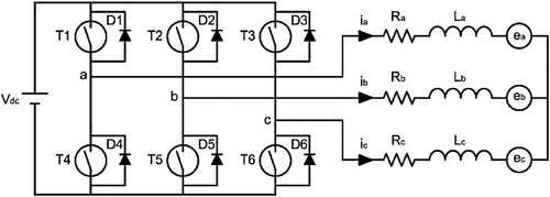
The equivalent circuit of a BLDC motor drive is depicted in Figure . The typical mathematical representation of the current dynamics in a BLDC motor drive is given by [Citation2]:
(1)
(1)
(2)
(2)
(3)
(3) with
(4)
(4) where
denote phase currents,
denote the phase voltages, R and L stand for the resistance and inductance for each of the three phases, respectively, and
are non-ideal back-EMF signals induced for each phase in the stator windings. Note that, the following assumptions are considered in modelling of the BLDC motor drive [Citation27]: Mutual inductance is zero for each winding, the phase resistances and the phase inductances are equal, and the motor neutral voltage is neglected. Those assumptions are quite common in control-oriented dynamical models of the electrical equivalent of the BLDC motor, and they are generally utilized to reduce the number of terms in the dynamical equations. The mechanical motion of the BLDC motor is expressed by
(5)
(5) where
denotes generated torque,
denotes the load torque, β stands for the viscous friction coefficient, J and ω denote the inertia moment and the rotor angular velocity, respectively. In the BLDC motor, the electromagnetic torque is given by the following expression:
(6)
(6) The amplitude of the back-EMF signals is proportional to the rotor speed while the form of the ideal back-EMF is usually considered to be trapezoidal in BLDC motors. Accordingly, the desired phase currents should have a rectangular form in order to generate a constant output torque in the ideal case. In the non-ideal case, the back-EMF signals have the form of quasi-trapezoidal or close to a sine-wave containing many harmonics. Therefore, it is not possible to obtain a constant torque output when the phase currents are in a rectangular waveform. As a result, fluctuations in output torque occur when a current controller is designed with the assumption that the back-EMF signals are trapezoidal since the output torque is directly related to the back-EMF signals and phase currents.
Figure 1. Configuration of BLDC motor drive.
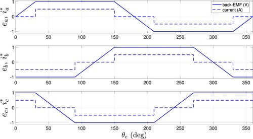
The variation of the ideal back-EMF signals and the change of corresponding phase current to obtain a constant output torque in ideal case is depicted in Figure . The amplitude of the back-EMF signals changes proportionally with the motor speed, so these signals alter in both frequency and amplitude with the rotor speed. The voltage variation in the back-EMF signals can be formulated as [Citation8]:
(7)
(7)
(8)
(8)
(9)
(9) where
is the back-EMF constant,
is the electrical angle of the rotor,
,
and
are the normalized auxiliary functions having the same waveform as the back-EMF signals and changing between
and 1. Besides, the relation between electrical and mechanical angles is defined by
(10)
(10) where P is the number of pole pairs. Utilizing (Equation7
(7)
(7) )–(Equation10
(10)
(10) ) in (Equation6
(6)
(6) ), one can obtain the expression for the torque output as
(11)
(11)
Figure 2. Change of trapezoidal back-EMF signals and corresponding desired phase currents.
Unlike DC motors having mechanical commutator and brush gear, the commutation occurs electronically in every 60 electrical degrees in the BLDC motor drives. All three phases are conducted during the commutation period while only two phases are active during the conduction period (see Chapter 10 in [Citation28] for details). The commutation brings a sudden and unexpected fluctuation in the phase currents directly acting on the output torque called the commutation torque ripple. In addition, as a result of the commutation, the BLDC motor drive dynamics is switched 12 times in one electrical cycle. Hence a strategy should be provided to cope with the model switching in order to reduce the adverse effects of the commutation.
In order to simplify further analysis and design procedure, suppose that the subscript x denotes the phase index with positive current and the subscript y is used for the phase having the negative current in the conduction period. Considering the balanced drive circuit given in Figure , the current dynamics of BLDC motor ((Equation1(1)
(1) )–(Equation3
(3)
(3) )) can be rewritten as
(12)
(12) where
,
,
,
and
and
Note that (Equation12
(12)
(12) ) gives the equivalent BLDC motor drive circuit model for a conduction period with two active phases assuming the remaining phase current is zero. For the sake of simplicity,
is defined as a combination of back-EMF signals of the conducting phases, and it is a periodic signal with 60 electrical degrees period as the conducted phases are switched in every 60 electrical degrees. Based on the dynamics introduced in (Equation12
(12)
(12) ), only two phases are assumed to be conducted in the controller design procedure as well. The periodic adaptation existing in the control structure has the ability of reducing the effects of the commutation period even though its effect is not included in the model. The proposed controller also deals with periodic uncertainties existing in the back-EMF signals as well as the other constant uncertainties available in the drive model. Note that since the back-EMF signals of all three phases are considered to be the same, the dynamic equations are quite similar for every 60
and the only change is the phase indices.
In this paper, the phase resistance and inductance values are considered uncertain, and the form of the back-EMF signals, corresponding to in (Equation12
(12)
(12) ), is considered non-ideal with time-varying periodic uncertainties. In order to overcome periodic uncertainties, a periodic update mechanism is proposed using only the previous period data. Unlike the constant uncertainties, since
is a periodic function with respect to the rotor displacement and since the rotor angular velocity changes by time in a variable-speed motor, the period of these signals is not constant. For this reason, the periodic adaptive controller identifying uncertain periodic signals with a constant period is not convenient for this problem. To overcome this issue, the time variable is changed in the current dynamics of the BLDC motor drive. Assuming
, suppose
(13)
(13) Utilizing that into, (Equation12
(12)
(12) ) can be reconstructed as
(14)
(14) In the next section, an adaptive current controller with a periodic adaptation rule is designed to reduce output torque fluctuation considering the switching phenomenon for the variable speed BLDC motor drives in the presence of constant and periodically varying uncertainties.
3. Controller structure
The controller design procedure for the minimization of the output torque fluctuations caused by parametric and time-varying uncertainties is described in this section. Note that the controller is designed based on the electrical equivalent of BLDC drive as the controller manipulates the torque output in order to reduce the effect of the uncertainties in terms of torque fluctuations. Although the mechanical part is not considered in the controller design scheme, that does not mean the mechanical part is completely ignored. This is a general approach in output torque control (see i.e. [Citation1–5]) and the reference smooth torque signal should be generated before modifying the control structure properly in case of speed control. To begin with the procedure, the phase current error is defined as
(15)
(15) where
is the desired phase current which is directly related to desired output torque. Taking the derivative of (Equation15
(15)
(15) ) with respect to angular displacement and substituting this result into (Equation14
(14)
(14) ), the phase current error dynamics can be derived as
(16)
(16) where
is the control input. The estimation error signals for the constant uncertain parameters (
,
) and the periodic uncertain signal (
) are defined as
(17)
(17)
(18)
(18)
(19)
(19) where
,
and
stand for the adapted signals of
,
and
, respectively. At this point, the control signal is introduced as
(20)
(20) with hybrid differential-periodic adaptation rules
(21)
(21)
(22)
(22)
(23)
(23) where
,
and
are positive constant adaptation gains, κ is a controller gain, and
is a function of
with the property given by
. It should be noted that the periodic adaptation mechanism (Equation21
(21)
(21) ) is updated with
periodicity due to the fact that
.
Taking into account the real-time implementation of BLDC motor drives based on digital data measurements, the proposed adaptive controller with hybrid differential-periodic adaptation rules cannot be applied directly as the periodic adaptation rule and control signal is designed in continuous time. Therefore, a practical modification is needed in the periodic adaptation rule. In order to solve this problem, the same number of samples in each period is used. For uncertain signal waveform, if the number of measured points in one period is N, then the periodic adaptation rule given in (Equation21(21)
(21) ) can be modified to
(24)
(24) where
denotes the instantaneous sampling points. Note here that N gives number of samples for each period of the uncertain signal, and it is a constant regardless of the period. Such a practical solution is necessary since the period changes with the motor speed, and N should be chosen depending on the drive specifications.
The periodic adaptation mechanism in the proposed controller has utilized the current error measurements collected in the previous period. Although the unknown signal form is assumed to be smooth, the current error measurements are critically affected by the commutation switching of the dynamical model occurring every 60 electrical degrees. As a result of this, undesired error on the related phase current gives rise to deterioration of the actual adapted values. Therefore, the adaptation approach needs further modifications in order to be convenient for practical applications. In this paper, the periodic adaptation is paused and the adapted signals are kept constant in the sampling period containing a model switch, and values obtained in the previous sample are utilized. After that modification, (Equation24(24)
(24) ) can be rearranged as
(25)
(25) where
means that there is no model switching due to the commutation between the two sampling instants k − 1 and k, while
means the occurrence of a model switching between the two sampling instants k − 1 and k. Note that
occurs twice only in every 60 electrical degrees as the commutation occurs only once every 60 electrical degrees. The reflection of undesired pulsation into the adapted parameters is avoided with the modification introduced in (Equation25
(25)
(25) ) by means of the switching signal
.
The system dynamics given in (Equation16(16)
(16) ) turns out to be
(26)
(26) after plugging in the adaptive controller (Equation20
(20)
(20) ) with adaptation rules given by (Equation17
(17)
(17) )–(Equation19
(19)
(19) ). This control signal ensures the asymptotic convergence of the error signal to zero. In order to prove that a Lyapunov-like approach is utilized which is given in detail in the next section.
4. Convergence analysis
The convergence analysis of the phase current error signals in the closed-loop system is presented in this section. Consider the positive definite function given by
(27)
(27) The difference of the positive-definite function
over one period can be obtained employing
(28)
(28) Using the error dynamics in (Equation26
(26)
(26) ), the difference of the first item on the right-hand-side of (Equation27
(27)
(27) ) over one period can be derived as
(29)
(29) The difference of the second term on the right-hand side of (Equation27
(27)
(27) ) over one period can be arranged using (Equation17
(17)
(17) ) as
(30)
(30) Using the fact that
and employing
, one can rearrange (Equation30
(30)
(30) ) as
(31)
(31) Then, substituting the periodic adaptation rule given in (Equation21
(21)
(21) ) into (Equation31
(31)
(31) ) and utilizing (Equation17
(17)
(17) ), the difference can be obtained as
(32)
(32) The difference of the third and fourth terms on the right-hand side of (Equation27
(27)
(27) ) over one period can be obtained utilizing the differential adaptation rules (Equation22
(22)
(22) ) and (Equation23
(23)
(23) ) as
(33)
(33)
(34)
(34) considering the fact that
and
are constantor changing very slowly (i.e.
and
). If the difference of the positive-definite function (Equation27
(27)
(27) ) over one period is reorganized with
, (Equation28
(28)
(28) ) turns out to be
(35)
(35) and hence
(36)
(36) is yielded. Note that the last term in (Equation35
(35)
(35) ) is eliminated to obtain (Equation36
(36)
(36) ) which does not change the stability result. On the other hand, (Equation35
(35)
(35) ) and (Equation36
(36)
(36) ) do not contain any other adaptation gain which is a part of the result of direct adaptive controller design procedure.
This result shows that the difference defined in (Equation28(28)
(28) ) which corresponds to the difference of (Equation27
(27)
(27) ) for each consecutive period is negative in terms of the current tracking error. Since this result is valid for every period where
, defining
and utilizing
(37)
(37) one can obtain
(38)
(38) for any
. Hence, since
is a positive definite function, it can be concluded that the sum of series in (Equation38
(38)
(38) ) is convergent if
is bounded as per
Therefore
can be obtained according to the convergence theorem. Now, we need to show the boundedness of
in order to complete the convergence analysis.
In order to show the boundedness of the positive-definite function (Equation27(27)
(27) ) in the interval
, the derivative of (Equation27
(27)
(27) ) with the respect to
in
can be determined as
Using
,
can be obtained where
. Utilizing Young's inequality,
can be resulted where
. Choosing γ such that
,
can be obtained. Since the uncertain periodic function is bounded, it can be concluded that
takes negative values outside of a compact set defined as
implying that the positive-definite function
is bounded for
.
Consequently, as the assumption on the boundedness of ) is relaxed, the tracking errors for the phase currents tend to zero asymptotically as
tends to infinity which completes the proof.
5. Simulation results
In order to demonstrate the performance of the proposed controller structure for the torque loop of the BLDC motor drives, several simulations have been performed in MATLAB, and the results are presented in this section. The mechanical part of the BLDC motor drive is ignored, but the shaft speed has been varied to emphasize its effects. Note that, in order to control the output torque of a BLDC motor, considering only the electrical equivalent is sufficient since the torque output can be manipulated by the phase currents which is clearly stated in (Equation11(11)
(11) ). The phase inductance and the phase resistance parameters are assigned as L = 2.5 mH and
. The rated phase-to-phase voltage value of the BLDC motor is set to 24 V, and the supply voltage of the 3 phase voltage-fed inverter is taken 24 V, thus the maximum voltage of the motor is saturated with 24 V accordingly. The switches of the inverter are considered ideal, and the frequency of PWM signals is assigned as 10 kHz. Hence, the sampling period of the controller is 100 µ s. The mathematical model is solved numerically using Euler approximation with 0.5 µ s fixed steps. The BLDC motor drive's nominal values utilized in the numerical simulations are adopted from [Citation2].
The parameters existing in the current dynamics have been considered uncertain taking into account the natural characteristics of the system parameters. 80 of the actual values of constant parameters (
) are used in the controller as their initial values. The periodic auxiliary signals
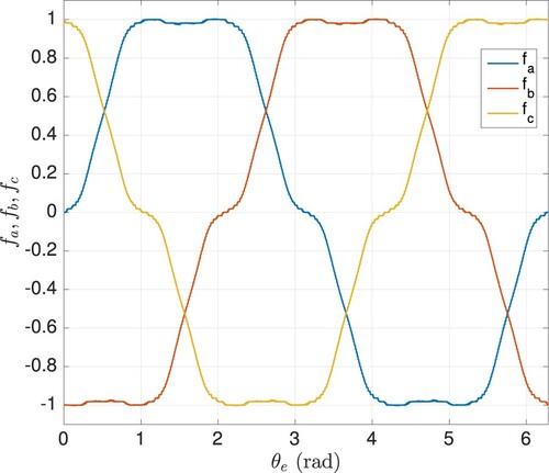
including un-identified harmonics are considered to be non-ideal. Auxiliary signals used in the simulations are illustrated in Figure for all phases. In the simulations, these auxiliary signals are assumed to be completely unknown, and their initial values in the controller are assigned as zero for the entire period. In addition to the completely unknown harmonics on the unknown auxiliary waveforms, the value of the constant term
in back-EMF signals is also not known by the controller. On the other hand, in order to produce the constant output torque, the reference currents are considered to be known by the controller.
Figure 3. Form of the back-EMF signals: ,
,
.
In simulations, the initial electrical angle is assigned as . The controller and the adaptation gains are set to
,
,
and
for all simulation cases. The fixed period for adaptation has been taken as 60 electrical degrees. The signals have been sampled with 1
, and N = 5000 giving the number of samples recorded in every adaptation period in the variable rotor speeds. The variable adaptation gain in the first adaptation period is considered a linear function of time and it has been set to
which is equal to 0 initially, and equal to
at the end of the first adaptation period for each simulation case. It is worth to mention here that there is no general rule for the tuning of the controller and adaptation gains to design the transient response since the closed-loop dynamics contains high order nonlinearities. Those parameters are adjusted to their given values based on simulation studies and practical concerns.
A high-frequency PWM switching also causes noise in the current samples and this phenomenon adversely affects the output torque. To minimize this effect, the current error signal utilized in adaptation is filtered with a low pass filter. On the other hand, this filter may not be sufficient for many undesired pulsations caused by unstructured dynamics and unpredictable disturbances encountered in practical motor drive applications. For instance, inverters used in the BLDC motor drive to produce the control signal can be considered as a disturbance source, as well as the noises existing in the measured signals. They lead to affect the adaptation procedure in practice. Some practical methods have been proposed in the literature to overcome these influences. For example, in [Citation21], a band interval with lower and upper boundaries which is known in advance is proposed. Once the estimated waveforms enter this band, the adaptation procedure is terminated. Since this method depends on a prior knowledge, the approach may not be convenient in case of a lack of knowledge about the limits of the actual uncertain signal. In this paper, to address this problem, the difference between the root-mean-square (RMS) values of the phase current errors for the last two consecutive periods is employed. Adaptation values are retained when the absolute value of the difference of RMS values calculated for the last two periods is lower than an arbitrarily determined bound. This limit value has been assigned as
in this study. It should be noticed that the bound value can be calibrated regarding different signals such as the output torque and adapted signals.
Various numerical simulations have been carried out to test the proposed periodic adaptive control structure under different conditions. Particularly, these simulations have been implemented for different shaft speeds and adaptation gains. Conducted numerical simulations are named differently depending on the simulation specifications introduced as follows:
This simulation has been run for
with the proposed controller.
Different from Sim #1, the shaft speed is given by
In order to demonstrate the effect of the periodic adaptation gain, the adaptation gain is assigned as
Different from Sim #1, the controller implemented in this simulation has no adaptation in order to show the contribution of the adaptation. 80
The controller applied in Sim #4 is implemented in this simulation for
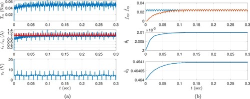
Figures (a) and (a) depict the change of the torque output (), the change of the reference conducting phase current and the change of the conducting phase current, the change of the applied voltage to the conducting phases and the change of the adapted signals obtained in Sim #1 and Sim #2. The simulation results confirm that the average phase current error decreases monotonically in each period of adaptation and phase currents are successfully track the reference current signals regardless of the rotor speed.
Figure 4. Results of Sim #1: Proposed controller with for
rpm. (a) The change of the output torque (top), reference and real conducting phase currents (middle), conducting phase voltage (bottom) and (b) The change of the periodic adapted parameter and its reference (top), adapted constant parameters (middle and bottom).
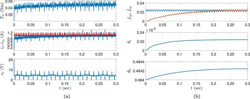
Figure 5. Results of Sim #2: Proposed controller with for
rpm. (a) The change of the output torque (top), reference and real conducting phase currents (middle), conducting phase voltage (bottom) and (b) The change of the periodic adapted parameter and its reference (top), adapted constant parameters (middle and bottom).
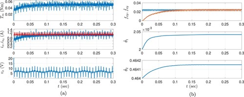
In Figures (b) and (b), change of the time-varying adaptation () and the adapted constant parameters (
) are given, respectively. The convergence of the estimated signal (
) to the actual signal can be observed in the results. Considering the periodic adaptation, the simulation results validate that the undesired effect of sudden changes on adapted signals is solved with the proposed modification despite the existence of instantaneous commutation which has an adverse effect in the output torque and current signals. This result reveals further the performance of the proposed adaptive controller under model switching as well as in driving the phase current errors to zero under the existence of unstructured dynamics and time varying or time invariant uncertainties. Another important outcome of the proposed adaptation method is that the adapted signals converge to the real structure of original signals without any prior knowledge about the form of the periodic unknown signal.
Sim #3 is performed to illustrate the effect of the periodic adaptation gain that is set as which is the only difference between Sim #1 and this simulation. Similar to the presentation of the previous simulation results, results of Sim #3 is depicted in Figure . Comparing Sim #1 and Sim #3 in terms of the output torque and conducting phase current, a faster convergence can be noted which is a direct result of the convergence speed in the adapted periodic signal. Hence, the convergence rate can apparently be adjusted utilizing the adaptation gain properly.
Figure 6. Results of Sim #3: Proposed controller with for
rpm. (a) The change of the output torque (top), reference and real conducting phase currents (middle), conducting phase voltage (bottom) and (b) The change of the periodic adapted parameter and its reference (top), adapted constant parameters (middle and bottom).
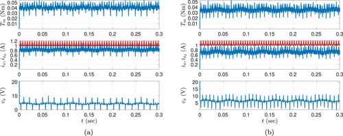
To demonstrate the contribution of the proposed controller further, the same controller structure without any adaptation has been performed in two simulations (Sim #4 and Sim #5). Note that, both the form of the back-EMF signals and the harmonics existing in these signals directly affect system performance. The desired phase currents, variable speed trajectories, and all controller parameters used in the simulations of the proposed controller are employed as they are in the simulations without adaptation mechanism. The results of the Sim #4 and Sim #5 are presented in Figure (a,b), respectively. According to the results of these simulations and the results of the proposed controller (given in Figures and ), the contribution of the proposed adaptation mechanism is evident. Note also that, the phase current errors and accordingly the torque output error do not converge to zero because of the constant uncertain parameters and periodic unknown signals that are compensated when the proposed controller is applied. Moreover, the torque ripples caused by uncertain signals can also be observed in the output torque and the conducting phase current which are clearly reduced with the proposed control structure.
Figure 7. Results for the controller without adaptation. (a) Sim #4 ( rpm): The change of the output torque (top), reference and real conducting phase currents (middle), conducting phase voltage (bottom) and (b) Sim #5 (
rpm): The change of the output torque (top), reference and real conducting phase currents (middle), conducting phase voltage (bottom).
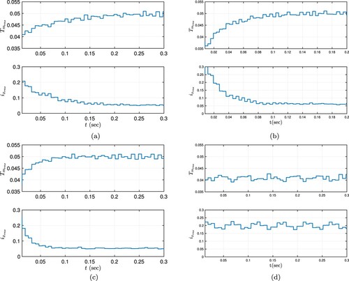
The RMS values of the output torque and the phase currents calculated for each period are given in Figure for Sim #1–4. Notice that the decision on the termination of the adaptation has been employed considering the obtained RMS values of phase currents in Sim #1–3. The main contribution of the proposed controller in terms of torque ripple reduction can be noted from the RMS values of the output torque error and phase current errors. The RMS of the current error converges to the values very close to zero in Sim #1–3 complying with the theoretical result (see Figure (a,c)). The reason for not having ultimate zero values is the PWM switching which does not allow the currents to be constant on or around the desired value. On the other hand, the current error does not converge to zero when the adaptation is not active (see Figure (d)). It is worth also mentioning that the conducting current fluctuates as a result of the unknown time-varying back-EMF signals which do not exist when the proposed controller is applied. Consequently, comprehensive simulation studies indicate the success of the proposed periodic adaptive controller aiming to regulate the phase currents in variable speed BLDC motor drives under different operation conditions.
Figure 8. The change of RMS values of the output torque and the conducting current along the adaptation periods for Sim #1–Sim #4. (a) Sim #1: RMS of the output torque (top), RMS of the conducting phase current (bottom). (b) Sim #2: RMS of the output torque (top), RMS of the conducting phase current (bottom). (c) Sim #3: RMS of the output torque (top), RMS of the conducting phase current (bottom) and (d) Sim #4: RMS of the output torque (top), RMS of the conducting phase current (bottom).
6. Conclusion
This paper addresses an adaptive controller based on periodic updating to minimize the torque ripples in variable speed uncertain BLDC motor drives. In order to regulate the phase currents, the electrical dynamics under parametric and time-varying uncertainties are introduced firstly by transforming the time coordinate into angular displacement. In this way, the variable frequency in the time-domain of unknown periodic waveform is fixed to one cycle angular displacement. Then, the hybrid adaptation laws have been introduced for the torque loop of BLDC motor drive considering the switched model leading to undesirable torque ripples. By injecting all adapted parameters into the control law, torque ripple rejection is realized. The convergence of the signals in the closed-loop system has been proven with the employment of a Lyapunov–Krasovskii functional. Detailed simulations taking into account all the issues in the practical applications have successfully been carried out to demonstrate the effectiveness and robustness of the proposed control scheme against the parameter changes in uncertain BLDC motor drives.
Disclosure statement
The authors declared no potential conflicts of interest with respect to the research, authorship and/or publication of this article.
Additional information
Funding
References
- Shi J, Li T-C. New method to eliminate commutation torque ripple of brushless DC motor with minimum commutation time. IEEE Trans Ind Electron. 2012;60(6):2139–2146.
- Türker T, Khudhair IOK. A switched current controller with commutation delay compensation for the reduction of commutation torque ripple in BLDCM drives. Turk J Elec Eng Comp Sci. 2017;25(4):2635–2646.
- Lu H, Zhang L, Qu W. A new torque control method for torque ripple minimization of BLDC motors with un-ideal back EMF. IEEE Trans Power Electron. 2008;23(2):950–958.
- Fang J, Li H, Han B. Torque ripple reduction in BLDC torque motor with nonideal back EMF. IEEE Trans Power Electron. 2012;27(11):4630–4637.
- Shakouhi SM, Mohamadian M, Afjei E. Torque ripple minimisation control method for a four-phase brushless DC motor with non-ideal back-electromotive force. IET Electr Power Appl. 2013;7(5):360–368.
- Aghili F. Adaptive reshaping of excitation currents for accurate torque control of brushless motors. IEEE Trans Control Syst Technol. 2008;16(2):356–364.
- Boroujeni MS, Markadeh GRA, Soltani J. Torque ripple reduction of brushless DC motor based on adaptive input-output feedback linearization. ISA Trans. 2017;70:502–511.
- Chen X, Liu G. Sensorless optimal commutation steady speed control method for a nonideal back-EMF BLDC motor drive system including buck converter. IEEE Trans Ind Electron. 2019;67(7):6147–6157.
- Xia C, Jiang G, Chen W, et al. Switching-gain adaptation current control for brushless DC motors. IEEE Trans Ind Electron. 2015;63(4):2044–2052.
- Boroujeni MS, Markadeh GA, Soltani J, Torque ripple reduction of brushless DC motor with harmonic current injection based on integral terminal sliding mode control. IET Electr Power Appl. 2017;12(1):25–36.
- Shi T, Cao Y, Jiang G, et al. A torque control strategy for torque ripple reduction of brushless DC motor with nonideal back electromotive force. IEEE Trans Ind Electron. 2017;64(6):4423–4433.
- de Almeida PM, Valle RL, Barbosa PG, et al. Robust control of a variable-speed BLDC motor drive. IEEE Trans Emerg Sel Topics Power Electron. 2020;2(1):32–41.
- Valle RL, De Almeida PM, Ferreira AA, et al. Unipolar PWM predictive current-mode control of a variable-speed low inductance BLDC motor drive. IET Electr Power Appl. 2017;11(5):688–696.
- Darba A, De Belie F, D'haese P, et al. Improved dynamic behavior in BLDC drives using model predictive speed and current control. IEEE Trans Ind Electron. 2015;63(2):728–740.
- EshkeVvari AL, Torkaman H. Simplified model predictive current control of non-sinusoidal low power brushless DC machines. Turk J Elec Eng Comp Sci. 2020;28(4):2288–2302.
- Xia C, Xiao Y, Chen W, et al. Torque ripple reduction in brushless DC drives based on reference current optimization using integral variable structure control. IEEE Trans Ind Electron. 2013;61(2):738–752.
- Shakouhi M, Mohamadian M, Afjei E. Fault-tolerant control of brushless DC motors under static rotor eccentricity. IEEE Trans Ind Electron. 2014;62(3):1400–1409.
- Wang Y, Gao F, Doyle III FJ. Survey on iterative learning control, repetitive control, and run-to-run control. J Process Control. 2009;19(10):1589–1600.
- Mattavelli P, Tubiana L, Zigliotto M. Torque-ripple reduction in PM synchronous motor drives using repetitive current control. IEEE Trans Power Electron. 2005;20(6):1423–1431.
- Qian W, Panda SK, Xu J-X. Torque ripple minimization in pm synchronous motors using iterative learning control. IEEE Trans Power Electron. 2004;19(2):272–279.
- Xu J-X. A new periodic adaptive control approach for time-varying parameters with known periodicity. IEEE Trans Automat Contr. 2004;49(4):579–583.
- Abidi K, Xu J-X. A discrete-time periodic adaptive control approach for time-varying parameters with known periodicity. IEEE Trans Automat Contr. 2008;53(2):575–581.
- Xu J-X, Huang D. Spatial periodic adaptive control for rotary machine systems. IEEE Trans Automat Contr. 2008;53(10):2402–2408.
- Abidi K. Spatial periodic adaptive control approach for rotary systems in sampled time. Int J Robust Nonlinear Control. 2014;24(7):1177–1188.
- Adıgüzel F, Türker T. An adaptive controller for the torque loop of BLDCM with unknown back-EMF signals. In: 2019 11th Int. Conf. on Electrical and Electronics Engineering (ELECO). IEEE; 2019. p. 744–748.
- Adıgüzel F, Türker T. A discrete-time adaptive current controller for BLDCM with uncertain back-EMF signals. In: 2020 Int. Conf. on Computation, Automation and Knowledge Management (ICCAKM). IEEE; 2020. p. 537–542.
- Krishnan R. Permanent magnet synchronous and brushless DC motor drives. Boca Raton, FL, USA: CRC press; 2017.
- Chiasson J. Modeling and high performance control of electric machines. Vol. 26. New York, NY, USA: John Wiley & Sons; 2005.