
 ?Mathematical formulae have been encoded as MathML and are displayed in this HTML version using MathJax in order to improve their display. Uncheck the box to turn MathJax off. This feature requires Javascript. Click on a formula to zoom.
Abstract
Nowadays, the use of renewable energy systems, especially fuel cells, has become very widespread in various applications. Some of their most important applications include using electric vehicles and local off-grid power systems. One of the challenges with the fuel cells is the slow dynamic response to load power changes. In fact, when the load power changes suddenly, the fuel cell supplies it with a time delay, and this can cause disturbances in the performance of the loads. In this research, a new control method for a bidirectional DC/DC converter equipped with a superconducting magnetic energy storage system (SMES) is presented to exchange the stored energy with the proton-exchange membrane fuel cell (PEMFC) in a high response dynamic to overcome the slow dynamic of the fuel cell feeding load. The appropriate validation of the proposed system is verified by simulation in the MATLAB SIMULINK environment. The results illustrate that the slow-response of PEMFC is improved appropriately.
1. Introduction
Fuel cells (FC) as one of the renewable energies have recently been highly regarded by various researchers and investors. In particular, the companies producing electric vehicles and local distribution loads pay special attention to it as one of the methods of producing pollution-free electricity. Fuel cell systems can generate electrical power with high efficiency across a wide range of sizes and situations. As FCs can be implemented in small sizes, they can be located near the electrical loads, enabling the thermal energy provided as a result of the chemical reaction to be used for cogeneration applications, making the combined efficiency even more attractive. Moreover, the FC systems usually emit a low level of common air pollutants and reduce carbon dioxide emissions. These systems operate silently. In contrast to the wind and solar systems, they have a dispatchable and predictable distributed generating technology [Citation1]. Research work has [Citation2] discussed the optimal estimation of proton exchange membrane fuel cell (PEMFC) parameters based on coyote optimization algorithms. A novel control strategy for enhancing microgrid operations connected to photovoltaic generation and energy storage systems is being investigated [Citation3]. Abubakr et al. [Citation4] analysed a comprehensive review of renewable energy sources in Egypt's current status, grid codes and future vision. Some of the most important challenges of the FCs are reviewed in the following.
One of the most common uses of the FCs is in electric vehicles. In any case, there is an unavoidable issue that the required power in electric vehicles varies due to time. This issue makes the FC operate under dynamic loads. Subsequently, water flooding or layer drying out, which antagonistically decreases the lifetime of the FC, may happen. To increase the lifetime of the FCs during the sharp dynamic load demands, experts have tried to optimize the materials, structures and control systems to enhance the operating condition inside the FCs [Citation5]. Due to the electro-osmotic drag, the water in the anodic ionomer moves rapidly with the protons to the cathode, while the current increases. This causes the rapid dehydration of ionomers in anodes and also leads to a high Ohmic overvoltage. Also, cathode flooding occurs because of the increased water generated by the reaction and movement by protons. This event causes an increase in mass transfer loss because of the difficulty in O2 mass transfer [Citation5]. With the back-diffusion process and absorption of the membrane, the water in the anode is being reallocated and the Ohmic over-voltage decreases again [Citation5]. This can be a major obstacle to the instantaneous acceleration of electric vehicles using FCs. It is also an important issue in supplying electricity to the consumers who are locally fed from the FCs and are not connected to the grid. In this case, if the load demand increases suddenly, the FC is not able to supply the load demand quickly. In addition to depreciation, the voltage and current of the load will not be stable, which can be harmful to some loads. In the following, it is assumed to investigate and review other research articles to overcome this phenomenon.
Many studies such as [Citation6–13] used energy storage system (EES), especially supercapacitors to improve the low dynamic response of the PEMFC. In [Citation6], researchers used a supercapacitor equipped with a bidirectional DC/DC converter to release or absorb high power density to the load in rapid load changes. The simulation results showed that the EES performed well against load fluctuations. Authors [Citation7] proposed a new system based on energy management and control strategy for a doubly fed induction generator (DFIG) based wind turbine/FC system equipped with a supercapacitor to control and manage the hybrid system in rapid load changes appropriately. A combination of photovoltaic (PV) and FC systems forms a good pair with acceptable performance for distributed generation applications [Citation8]. Many researchers have focused their work similarly. Authors [Citation9] proposed a completely decentralized energy management system with high reliability for the FC and supercapacitor based on an energy storage system. Improving the lifetime of solid oxide FC with the new backup battery converter was proposed and investigated in [Citation10]. In [Citation11], researchers proposed a real-time predictive energy management strategy for the FC/battery/ ultra-capacitor hybrid energy storage system in electric vehicles which mainly focused on the management of EES to improve the performance of FCs in electric vehicles.
Other research such as [Citation14–18] are based on battery systems to overcome the low dynamic response of PEMFC, but the main drawback of this system is the low power density of batteries and limitation of batteries' lifetime. Usually, a supercapacitor storage device is preferable due to its high power density, high dynamics, and long lifetime rather than a battery [Citation8]. For instance, authors [Citation14] proposed a novel energy management policy based on FC/battery power sources for electrical scooter supply. In other research, authors proposed a control strategy of a fuel cell-battery hybrid system for optimizing the lift truckload cycle [Citation15]. In [Citation16], the authors proposed a simulation analysis of the fuel economy of an FC/battery passive hybrid power system for commercial vehicles. A rule-based energy management strategy for an FC/ battery hybrid locomotive is being investigated [Citation17] as new research based on hybrid usage of FC and batteries to improve the FC performance during variable loadings. Another similar research investigated [Citation18] is based on multi-objective optimal predictive energy management for FC/battery hybrid construction vehicles.
Some research such as [Citation19] used SMES to improve the operation of PEMFC. Authors [Citation20] suggested using the SMES/battery besides PEMFC in space applications. The aim of using EES is to improve the PEMFC capability to feed different electrical load variations. The other important matter investigated [Citation21] is the design and implementation of SMES and other EESs feeding different loads such as electric vehicles. Although using EES such as SMES can improve the dynamic response of PEMFC and other renewable energies, their control systems have some difficulties. In [Citation22] the authors proposed a new control method based on pulse width modulation in current source converters (PWM-CSC) to manage the active and reactive power absorbed by the SMES independently. Moreover, another difficulty that the SMES systems face with is their cooling systems having to remain superconducting in different conditions. New research on M-SMES temperature equilibrium control strategies considering state assessment is being investigated [Citation23].
Also, researchers [Citation24,Citation25] have proposed and implemented different SMES cooling systems, such as developing a cryogen-free cooled SMES demonstrator based on MgB2. Some other researchers [Citation26] worked on improving the efficiency of hybrid fuel cell-based vehicles through energy management strategies through online systemic management of fuel cells. Also, researchers [Citation27] proposed an optimal fuzzy logic control for an FC hybrid electric vehicle based on particle swarm and advisor to improve the performance of the fuel cells. Another research represented a comparative study of a PEMFC, battery and supercapacitor based energy source owing to the hybrid vehicle to improve the FC dynamic response [Citation28]. Interesting research based on the performance of the SMES system with a non-linear dynamic evolution control approach for pulsed power load compensation is investigated and analysed in [Citation29] while the authors formulated the SMES system connected to a DC/DC converter so brilliantly with a new control method for the converter to absorb or release the desired power by the SMES. Another related research for SMES technology systems is represented in [Citation30]. The authors proposed an SMES/battery hybrid energy storage system based on a bidirectional Z-source inverter for electric vehicles. In [Citation31], a coordinated-control strategy of scalable superconducting magnetic energy storage under an unbalanced voltage condition is being investigated.
As reviewed, a few articles have addressed the use of SMES in the FCs as energy storage, and most of them generally use supercapacitors or batteries. As a result, the pristine use of this system led us to consider using the SMES alongside PEMFC. In this paper, the proposed method is based on a DC/DC converter to use the energy stored in SMES in such a way that during a sudden increase in load with the help of an FC in the supply of load power and while the load power decreases, the surplus energy is saved. The proposed control system for controlling the relevant converter was proposed and studied and simulated in the MATLAB environment, and the results illustrate the appropriate operation of the proposed system to improve the dynamic response of the FC to load demand supply.
2. PEMFC modelling
The PEMFC develops as one of the best candidates for electric vehicles because of its straightforwardness, practicality, speedy beginning up, lower working temperature, higher control thickness and general electrical effectiveness compared to some sized internal combustion engines. The output voltage in an FC under the standard state condition (25°C and 1 atm.) is near 1.229 V [Citation5]. Although the practical voltage of FC is usually less than the perfect one because of the non-reversible voltage drops happening in FC systems, this is mentioned in . The voltage drops in an FC system can be divided into three terms, which are non-reversible voltage drops. They are specific voltage drop, resistive voltage drop and concentration voltage drop. At low current conditions, the activation voltage drop is capable of the voltage drop of the FC. Concentration over voltage is more important at high current densities. The impacts of these three voltage drops and comparing the variation of FC voltage are illustrated from its polarization diagram in . The foremost proficient working locale for the FC is the straight locale compared to the cell voltage between 0.55 and 0.8 V, as shown in . The FC operation in this linear region is very imperative for system efficiency. The equations representing the voltage of the PEMFC are mentioned below [Citation6]
(1)
(1)
(2)
(2)
Figure 1. Simple FC polarization diagram [Citation6].
![Figure 1. Simple FC polarization diagram [Citation6].](/cms/asset/dca89ba1-2f1f-4bc5-abbd-876fe018494a/taut_a_2066768_f0001_ob.jpg)
In the above equations, the,
,
,
,
,
are FC output voltage, the Nerst chemical voltage produced by the FC, activation voltage drop, concentration voltage drop, Ohmic voltage drop and the FC temperature, respectively. The relative pressures of hydrogen and oxygen (
and
) are assumed to change between predefined lower and upper limitations for anode and cathode pressures. These pressures are inversely relative to the molar H2 and O2 flows and appropriately to the FC current. The molar H2 pressure that responds to an arrangement to meet the load variations can be inferred as Equation (3), while the temperature variations of the FC can be represented as Equation (4) [Citation6]
(3)
(3)
(4)
(4)
Also, the activation voltage can be calculated as follows, while the
is the dissolved oxygen concentration in the interface of the cathode catalyst.
(5)
(5)
As Henry's law describes, the dissolved O2 concentration value at the gas or liquid interface can be represented as Equation (6), while the is the utilization factor of FC can be defined as Equation (7). The utilization factor is one of the important variables of the FC that describes the ratio of the flow of the hydrogen reacted (
) to the input hydrogen flow (
). This parameter is proportional to the FC current and must be less than unity. This means the rapid load current increase can overload the FC and the protective devices will trip the FC due to protective scenarios [Citation5,Citation6]
(6)
(6)
(7)
(7)
where the
,
are the FC stack numbers and current, respectively. The next voltage drop, named Ohmic voltage drop, can be expressed by multiplying the FC current into the resistance of the FC electrolyte and other connecting equipment and wires as mentioned in Equation (8)
(8)
(8)
where the
represents the concentration Ohmic resistance of FC and also by Ohm's law the resistance of
can be defined as follows:
(9)
(9)
where the
and
are the FC stack length and area. The Nafion series proton exchange membrane resistivity mentioned in Equation (9) can be determined as below
(10)
(10)
(11)
(11)
where
is the water content of the membrane. Equation (12) represents the concentration voltage of the FC and is defined as the voltage drop that is caused by the transportation of mass within the cell. This transportation influences the H2 and O2 concentrations effectively, particularly at high current densities.
(12)
(12)
One of the important issues in FC systems is the double-layer charge effect of the capacitor. The FC equivalent circuit considering the capacitor effect is shown in . The capacitor shows the layer of electrical charge on or close to the electrode–electrolyte interface, which is the capacity for electrical charge and vitality. Considering the impact of this effect, the elements of the FC yield voltage can be obtained more precisely [Citation6]. As shown in , it could be a variable resistance that represents the actuation, and concentration voltage drops are mentioned below.
(13)
(13)
According to the equivalent FC circuit, as shown in , the KCL law can be written as Equation (14). Therefore, the output voltage of the FC can be calculated as Equation (15)
(14)
(14)
(15)
(15)
Therefore, the output voltage of a series stack of a number of FCs is represented below.
(16)
(16)
illustrates the demonstration of the PEMFC based on the mentioned formulas, which were inserted into the MATLAB environment. Experiments show that the protection system of the FC limits the utilization factor (U) to more than 0.7 and also less than 0.9, (0.7 < U < 0.9), elsewhere the protection system trips the FC. As conferred from Equation (7), the utilization factor is proportional to the FC current. Therefore, the immediate increase in load current increases the utilization factor. It is clear that the sharp variation of FC current will cause a trip command to FC in each stack. shows the fundamental parameters of the FC used in the simulation process [Citation6].
Figure 2. FC electrical equivalent circuit.
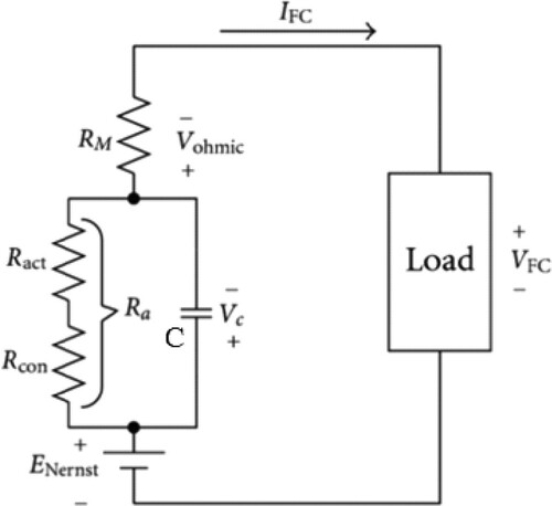
Figure 3. Simplified model of the FC system [Citation6].
![Figure 3. Simplified model of the FC system [Citation6].](/cms/asset/324e320c-780e-47c5-8bbe-d66ced4ca982/taut_a_2066768_f0003_oc.jpg)
Table 1. Parameters of the fuel cell used in the simulation [Citation6].
3. SMES and converter system modelling
In the following the SMES and DC/DC bidirectional converter modelling are investigated.
3.1. SMES modelling
The most viewpoint of the SMES system is superconducting materials which are free of dissipation since there is no resistance to these materials. The coil is made of these materials to mitigate conductive energy loss. High-density energy is stored in the magnetic field. The biggest challenge of the SMES unit systems is keeping the coil within the superconducting state, in which the cryogenic system is capable of acting appropriately and in the presence of a protective system to secure the SMES under irregular conditions. The impedances between the grid and the SMES coil can be accomplished by the control of electronic converter circuits. The DC/DC bidirectional converter used to accomplish SMES in FC application is illustrated in , Equation (17) and Equation (18) represent the SMES power () and the energy (
) in terms of the magnet coil inductance (
), where are the SMES voltage (
) and current (
) respectively.
(17)
(17)
(18)
(18)
Figure 4. Schematic of the bidirectional DC/DC converter equipped with SMES [Citation32].
![Figure 4. Schematic of the bidirectional DC/DC converter equipped with SMES [Citation32].](/cms/asset/a7e94531-2059-4067-b391-97ca88dfe589/taut_a_2066768_f0004_oc.jpg)
3.2. Bidirectional converter modelling
In , the topology of a bidirectional DC/DC converter is illustrated to interconnect the SMES system to the FC for charge and discharge appropriately. As shown in , by adjusting the duty cycle (D) of the switches S1 and S2, the average power exchanged by the SMES system can be controlled in a flexible condition in each switching period. The equation demonstrates the relation between the power of SMES and its current as modelled as the following [Citation32]:
(19)
(19)
It can be inferred that while D > 0.5, the SMES will absorb energy by conducting the source current from S1 and S2, thus the SMES will charge. Elsewhere, while D < 0.5, the SMES will release the stored energy into the load by conducting the D1 and D2.
3.3. Proposed bidirectional DC/DC converter control system
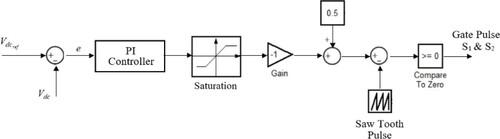
The proposed system to control the bidirectional DC/DC converter is presented in , which is based on a PWM system and PI controller. In the proposed control system, the difference between and
is delivered to a PI controller to produce the appropriate control signal to eliminate the steady-state error. The output of the controller is passed through a saturation block, which limits the signal between −1 and +1 to prevent high values and saturation. In the following, the produced signal is added by a constant value of 0.5 and compared to a sawtooth pulse (PWM) to produce the gate pulses which drive the bidirectional converter. Consider when the FC is in a stable condition and the load power is constant and the FC is producing the whole load power. In this condition, it is expected that the SMES power is equal to zero. So the values of
and
are the same. Thus, the error signal is equal to zero. Also, by adding a constant value of 0.5 and comparing it with a saw tooth pulse that varies between 0 and 1, the produced duty cycle of 50% is generated. Due to Equation (19), the active power released/absorbed by the SMES is equal to zero, which means appropriate operation. In another condition, while the load increases rapidly, so the error voltage signal increases and by passing through the saturation block and other items, the duty cycle will decrease, which means releasing the SMES stored energy to the load and vice versa. The main advantages of the proposed method to other similar research are the simplified implementation, fast dynamic and accurate response with zero steady-state error.
Figure 5. Proposed control block diagram of the bidirectional DC/DC converter.
4. Simulation results
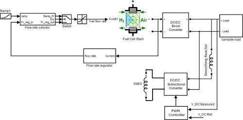
It is assumed to analyse, review and discuss the simulation results of the proposed system in this section. illustrates the schematic of a 10 kW, 45 V PEMFC connected to a bidirectional DC/DC converter equipped with SMES into a variable DC load. As shown, the FC system is connected to the load through a boost DC/DC converter to compensate for the variations in the output voltage of the FC due to variations in load power demand and to deliver a stabilized voltage into the load. Moreover, the proposed system includes a bidirectional DC/DC converter to connect the SMES, which is connected to the DC link through a current smoothing inductance. The bidirectional converter is controlled by the proposed PWM controller to release or absorb enough energy due to load demand variations.
Figure 6. Schematic of the FC connected with bidirectional DC/DC converter with SMES.
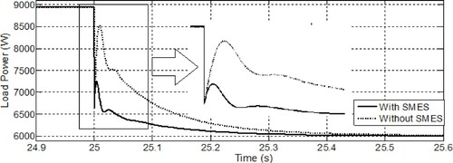
illustrates the variations of the load power demand in the presence and absence of the SMES system. As illustrated, the load power is increased +50% suddenly at second. According to the diagram, it can be inferred that in the absence of the SMES, it takes longer to fully supply the load power, and this causes more pressure on the FC system. Similarly, investigates the same diagram in a condition where the load power is accompanied by a sudden decrease of −50% at
second.
Figure 7. Load power increasing with and without SMES.
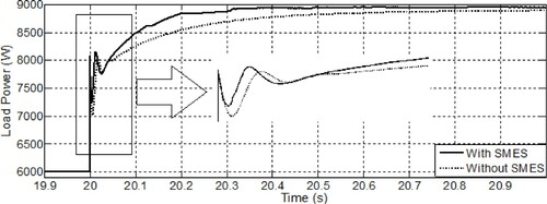
Figure 8. Load power decreases with and without SMES.
Figures and show the load voltage (DC link voltage) diagram in two modes of presence and absence of the SMES system, while the load increases and decreases. As can be seen, the SMES and the bidirectional converter were able to relatively smoothen the load voltage fluctuations more, while the load power changes. It is inferred from that while the load demand power increases, the DC link voltage drops to overcome the instantaneous load power increase. The important matter is in case of the FC equipped with the bidirectional DC/DC converter and SMES, the depth of voltage drop is less than in the case of without SMES.
Figure 9. DC link voltage variation while load increasing with and without SMES.
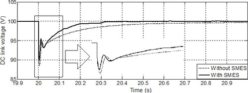
Figure 10. DC link voltage variation while load decreasing with and without SMES.
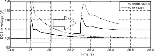
Also it is noticeable from that while the load demand power decreases, the DC link voltage increases to absorb the instantaneous load power reduction. The important matter is in case of the FC is equipped with a bidirectional DC/DC converter and SMES, the overshoot of the voltage increase is less than in the case without SMES.
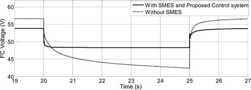
illustrates the FC output voltage in each of the two mentioned conditions. It is inferred that the SMES is able to reduce the FC voltage fluctuations during the load changes.
Figure 11. FC stack voltage variation with and without SMES.
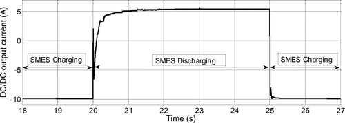
The DC/DC bidirectional converter’s current is illustrated in , which shows the SMES charging or discharging energy states. Before the load demand increases, the bidirectional converter is in absorbing energy mode, so its current is negative, while after the load demand increases at seconds, the SMES releases the stored energy into the load periodically, so the current increases to a positive value. Finally, after the load demand reduction, the SMES condition is changed again to the charging mode.
Figure 12. DC/DC converter output current.
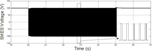
In the same condition, illustrates the SMES’s current while the charging and discharging conditions are shown. Also, the SMES’s voltage is illustrated in . In charging conditions, its voltage is positive and in discharging conditions, the voltage varies from negative to positive periodically with a negative average value.
Figure 13. SMES current.
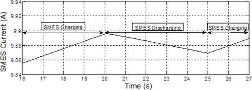
Figure 14. SMES voltage.
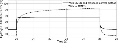
Finally, shows the diagram of the H2 utilization factor of the FC. As expected, in the presence of the SMES, the rapid fluctuations of this parameter are adjusted. As mentioned [Citation5,Citation6], preventing sudden variations of the utilization factor can increase the performance and lifetime of the FC. Moreover, the H2 utilization factor of FC exceeds 0.9 in the absence of SMES, which means the protective device will trip the FC, while the same factor is less than 0.8 in the presence of SMES.
Figure 15. The H2 utilization factor during the load variation with and without SMES.
represents the load response settling time comparison between the presence and absence of the SMES and bidirectional DC/DC converter, controlled by the proposed system. As inferred from , the SMES and bidirectional converter equipped with the proposed control system made an impressive performance to improve the FC response in load variations. This achievement can be used in various applications such as electric vehicles and microgrids.
Table 2. Load response settling time comparison in presence and absence of the SMES with the proposed control system.
5. Conclusion
In this research, the effect of using SMES with a new control system for a bidirectional converter to improve the FC performance was investigated. For this purpose, a DC/DC bidirectional converter controlled by a PWM-based control system was proposed, designed and investigated. The summary of the results shows that the FC system is not able to provide sudden load demand variations. In other words, the FC is able to provide the load demand within a time delay. To overcome the problem, the EES with the proposed control system was operated. It was not only able to compensate for the delay time well, but also by limiting the sudden variations in the utilization factor of the FC, it can increase its lifetime and provide better performance. The comparison between the presence and absence of the SMES with the proposed system illustrates a 35–52% improvement in settling time and a significant improvement in load demand feeding appropriately. For future studies, it is recommended to investigate the robustness test of the bidirectional converter due to load changes. All the simulation process is evaluated and simulated in a MATLAB/Simulink environment.
Disclosure statement
No potential conflict of interest was reported by the author(s).
References
- Lai J, Ellis MW. Fuel cell power systems and applications. Proc IEEE. 2017;105(11):2166–2190. doi:https://doi.org/10.1109/JPROC.2017.2723561.
- Abaza A, El-Sehiemy RA, Mahmoud K, et al. Optimal estimation of proton exchange membrane fuel cells parameter based on coyote optimization algorithm. Appl Sci. 2021;11(5):2052. doi:https://doi.org/10.3390/app11052052.
- Emara D, Ezzat M, Abdelaziz AY, Mahmoud K, Lehtonen M, Darwish MMF. Novel control strategy for enhancing microgrid operation connected to photovoltaic generation and energy storage systems. Electronics 2021;10:1261. doi:https://doi.org/10.3390/electronics10111261
- Abubakr H, Vasquez JC, Mahmoud K, et al. Comprehensive review on renewable energy sources in Egypt current status, grid codes and future vision. IEEE Access. 2022;10:4081-4101. doi:https://doi.org/10.1109/ACCESS.2022.3140385.
- Li X, Han K, Song Y. Dynamic behaviors of PEM fuel cells under load changes. Int J Hydrogen Energy. 2020;45(39):20312–20320. doi:https://doi.org/10.1016/j.ijhydene.2019.12.034.
- khani NG, Agha-Mirsalim M, Mastanabadi A. Dynamic response improvement of Fuel cell using ultra capacitor). Proceedings of the 5th Conference on Knowledge Based Engineering and Innovation (KBEI); 2019; Tehran. 2019. p. 443–448. doi:https://doi.org/10.1109/KBEI.2019.8734964.
- Kadri A, Marzougui H, Aouiti A, et al. Energy management and control strategy for a DFIG wind turbine/fuel cell hybrid system with super capacitor storage system. Energy. 2020;192:116518. doi:https://doi.org/10.1016/j.energy.2019.116518.
- Thounthong P, Luksanasakul A, Koseeyaporn P, et al. Intelligent model-based control of a standalone photovoltaic/fuel cell power plant with supercapacitor energy storage. IEEE Trans Sustainable Energy. 2013;4(1):240–249. doi:https://doi.org/10.1109/TSTE.2012.2214794.
- Song Q, Fan Z, Fang L, et al. Completely decentralized energy management system with high reliability for the Fuel cell-ultracapacitor auxiliary power unit. Proceedings of the 46th Annual Conference of the IEEE Industrial Electronics Society; 2020; Singapore: IECON. 2020. p. 3722–3726. doi:https://doi.org/10.1109/IECON43393.2020.9254437.
- Gorji JG, Kanani H, Abbaszadeh K. Improve a lifetime of solid oxide Fuel cell With The New backup battery converter). Proceedings of the 11th Power Electronics, Drive Systems, and Technologies Conference (PEDSTC); 2020; Tehran, Iran. 2020. p. 1–6, doi:https://doi.org/10.1109/PEDSTC49159.2020.9088371.
- Wang J, Zhou J, Xu D. A real-time predictive energy management strategy of fuel cell/battery/ ultra-capacitor hybrid energy storage system in electric vehicle. Proceedings of the Chinese Automation Congress (CAC); 2020; Shanghai, China. 2020. p. 3951–3954, doi:https://doi.org/10.1109/CAC51589.2020.9327653.
- Xun Q, Liu Y, Zhao J, et al. Modelling and simulation of Fuel cell/ Supercapacitor passive hybrid vehicle system). Proceedings of the IEEE Energy Conversion Congress and Exposition (ECCE); 2019; Baltimore, MD, USA. 2019. p. 2690–2696. doi:https://doi.org/10.1109/ECCE.2019.8913170.
- Yan Y, Li Q, Chen W, et al. Optimal energy management and control in multimode equivalent energy consumption of fuel cell/Supercapacitor of hybrid electric tram. IEEE Trans Industrial Electr. 2019;66(8):6065–6076. doi:https://doi.org/10.1109/TIE.2018.2871792.
- Boumediene S, Abdelfatah N, Hamza T, et al. Novel energy management policy based on Fuel cell/ battery power sources for scooter electric supply). Proceedings of the 7th International Conference on Electrical Energy Systems (ICEES); 2021; Chennai, India. 2021. p. 129–134. doi:https://doi.org/10.1109/ICEES51510.2021.9383690.
- Radica G, Tolj I, Lototskyy M, et al. Control strategy of fuel cell-battery hybrid system for optimizing lift truck load cycle). Proceedings of the 5th International Conference on Smart and Sustainable Technologies (SpliTech); 2020; Split, Croatia. 2020. p. 1–4. doi:https://doi.org/10.23919/SpliTech49282.2020.9243836.
- Xu L, Hu Z, Xu L, et al. Simulation analysis of fuel economy of a fuel cell/battery passive hybrid power system for commercial vehicles). Proceedings of the IEEE 4th International Electrical and Energy Conference (CIEEC); 2021; Wuhan, China. 2021. p. 1–5. doi:https://doi.org/10.1109/CIEEC50170.2021.9510209.
- Kang J, Guo Y, Liu J. Rule-based Energy Management Strategies for a Fuel cell-battery hybrid locomotive). Proceedings of the IEEE 4th Conference on Energy Internet and Energy System Integration (EI2); 2020; Wuhan, China. 2020. p. 45–50. doi:https://doi.org/10.1109/EI250167.2020.9346652.
- Li T, Liu H, Wang H, et al. Multiobjective optimal predictive energy management for fuel cell/battery hybrid construction vehicles. IEEE Access. 2020;8:25927–25937. doi:https://doi.org/10.1109/ACCESS.2020.2969494.
- Hamajima T, Amata H, Iwasaki T, et al. Application of SMES and Fuel cell system Combined With liquid hydrogen vehicle station to renewable energy control). IEEE Trans Appl superconductivity. 22(3): 5701704–5701704. doi:https://doi.org/10.1109/TASC.2011.2175687.
- Bizon N. Hybrid power sources (HPSs) for space applications: analysis of PEMFC/battery/SMES HPS under unknown load containing pulses. Renewable Sustainable Energy Rev. 2019;105:14–37. doi:https://doi.org/10.1016/j.rser.2019.01.044.
- Yang B, Zhu T, Zhang X, et al. Design and implementation of battery/SMES hybrid energy storage systems used in electric vehicles: a nonlinear robust fractional-order control approach. Energy. 2020;191:116510. doi:https://doi.org/10.1016/j.energy.2019.116510.
- Montoya OD, Gil-González W, Garcés A, et al. Indirect IDA-PBC for active and reactive power support in distribution networks using SMES systems with PWM-CSC. J Energy Storage. 2018;17:261–271. doi:https://doi.org/10.1016/j.est.2018.03.004.
- Guo S, Ren L, Xu Y, et al. Research on M-SMES temperature equilibrium control strategies considering state assessment. IEEE Trans Appl Superconductivity. 2021;31(6):5700508. doi:https://doi.org/10.1109/TASC.2021.3082082.
- Morandi A, Anemona A, Angeli G, et al. The DRYSMES4GRID project: development of a 500 kJ/200 kW cryogen-free cooled SMES demonstrator based on MgB2. IEEE Trans Appl Superconductivity. 2018;28(4):5700205. doi:https://doi.org/10.1109/TASC.2018.2793661.
- Zhu J, Chen P, Zhang H, et al. Design and characteristic study of a novel internal cooling high temperature superconducting composite cable With REBCO for energy storage applications. IEEE Trans Appl Superconductivity. 2018;28(3):4801305. doi:https://doi.org/10.1109/TASC.2017.2782665.
- Kandidayeni M, Macias A, Boulon L, et al. Efficiency upgrade of hybrid fuel cell vehicles’ energy management strategies by online systemic management of fuel cell. IEEE Trans Ind Electron. 2021;68(6):4941–4953. doi:https://doi.org/10.1109/TIE.2020.2992950.
- Tifour B, Boukhnifer M, Hafaifa A, et al. An optimal fuzzy logic control for a Fuel cell hybrid electric vehicle based on particle swarm and advisor. Proceedings of the IEEE Green Technologies Conference (GreenTech); 2021. p. 148–154, doi:https://doi.org/10.1109/GreenTech48523.2021.00033.
- Islam Tusher MM, Hoque ME, Uddin MJ, et al. A comparative study of a PEMFC, battery, super-capacitor based energy source owing to hybrid vehicle. Proceedings of the International Conference on Sustainable Technologies for Industry 4.0 (STI); 2019. p. 1–4, doi:https://doi.org/10.1109/STI47673.2019.9068061.
- Penthia T, Panda AK, Patnaik N, et al. Performance of SMES system with non-linear dynamic evolution control approach for pulsed power load compensation. IET Gen Trans Distribution. 2020;14(10):1872–1881. doi:https://doi.org/10.1049/iet-gtd.2019.1880.
- Choobdari Omran K, Mosallanejad A. SMES/battery hybrid energy storage system based on bidirectional Z-source inverter for electric vehicles. IET Electr Syst Transportation. 2018;8(4):215–220. doi:https://doi.org/10.1049/iet-est.2017.0100.
- Lin X, Lei Y, Fu W, et al. Coordinated-control strategy of scalable superconducting magnetic energy storage under an unbalanced voltage condition. IET Renew Power Gener. 2020;14(5):734–746. doi:https://doi.org/10.1049/iet-rpg.2019.0111.
- Chen L, Li G, Chen H, et al. Combined use of SFCL and SMES for augmenting FRT performance and smoothing output power of PMSG based wind turbine. Proceedings of the Asian Conference on Energy, Power and Transportation Electrification (ACEPT); 2018. p. 1–5, doi:https://doi.org/10.1109/ACEPT.2018.8610758.