
 ?Mathematical formulae have been encoded as MathML and are displayed in this HTML version using MathJax in order to improve their display. Uncheck the box to turn MathJax off. This feature requires Javascript. Click on a formula to zoom.
Abstract
Power electronic devices and variable speed drives solve a power quality issue. To increase the power quality, the distribution side must be compensated by concurrently infusing actual and reactive power. A cost-effective method of preventing voltage sag and swell in power electronic loads is the use of a dynamic voltage restorer. To enhance the power quality for end users, a DC-link component will be combined with the DVR. Ratings for DC-Link elements and inverters are more challenging when constructing a DVR. To simplify things, the Distributed Energy Source (DES) is combined with the DC-Link and the Inverter. The PV-integrated DVR is under the supervision of the Interval type-2 Fuzzy Logic Controller using Synchronous Reference Frame Theory. Reactive power is injected and absorbed under defective situations using a variety of injection techniques with various controllers. The suggested controller enhances power quality and provides exact results under different fault scenarios. Matlab is used to compare the proposed IT2-FLC to a type-1 fuzzy-adjusted PI controller and a traditional mathematical PI controller. The results of the simulations showed that the suggested methodology provided a better outcome on the Distribution side. To validate the simulation results, a scaled-down rating prototype model is created.
1. Introduction
The industry's renovation and computerization involve using power electronic devices and adjustable speed drives, significantly impacting PQ issues. Due to PQ issues, residential consumers are experiencing voltage amplitude variations and system frequency deviations that cause damage to the end-user appliances [Citation1]. On the distributed side, Voltage swell and Voltage sag are the most popular PQ issues. For the production of load electronic power, DVR is a cost-effective solution for Voltage sag and swell. The DVR is a device of series connection and it can be located in between the grid and load. A high isolation level of transformers is used in DVR to separate the distribution from generation [Citation2]. Many researchers are initiating new control methodologies and the end user power quality has been improving theories. The hybrid distribution transformer methodology is implemented in [Citation3], but this methodology improves the cost of the entire system and is more complicated to control. Modified control techniques in voltage transformers are introduced on the distribution side to improve the power quality [Citation4]. Various topologies and control methodologies are differentiated, with several control techniques presented in [Citation5]. Demonstration of the Z source Matrix converter-based DVR [Citation6] and the major snag is to control the methodology of matrix converters needs more control techniques. During Faulty scenarios, required amount of AC voltage can be injected into the grid with the dependency of DC-Link.
Now-a-days under the faulty scenarios the power supply has been continued to provide the grid integrated w = that has been with DES [Citation7]. The major snag of DES is extracting the maximum power from various environmental conditions. Nevertheless, under various environments from DES, the maximum power has been extracted to challenges lie. From DES to extract maximum power to extract that employs the technology MPP effectual In [Citation8–10], the authors described various MPP techniques such as Ripple Correlation (RCT), Incremental Conductance (INC) and Perturb & Observe (P&O) are used to extract the power.
Conventionally DVR needs a 1.5 times greater amount of DC-Link Voltage than the Grid Voltage. This increases the investment cost as well as requires more space [Citation11]. The proposed methodology reduces DC-Link Voltage and the magnitude of DVR will not get affected during compensation and indirectly reduces the size of DVR. The conventional mathematical PI controller is used along with the DVR to compensate for the fault in distribution. However, in transient conditions this methodology cannot be implemented based on PI controller gain values selection. Therefore, type-1 FLC is applied to generate the PI controller gain values [Citation7].
The challenge that lies in a distribution system is uncertainty. It may create electrical accidents in distribution. IT1-FLC has more uncertainty to overcome this problem [Citation12]; the author introduces the theoretical model of IT2-FLC. It can be compared with conventional IT1-FLC to verify the system of robustness. The significant difficulty of IT1-FLC uncertainty will be overcome in IT2-FLC. In [Citation13,Citation14], the authors prove the robustness of IT2-FLC for anaesthesia patient parameters with more uncertainty. The results proved that IT2-FLC gives better outcomes with more uncertainty. Based on the IT2-FLC, the proposed methodology will be implemented and with the type 1 fuzzy the outcomes are compared to that tuned PI controller and PI controller in conventional mathematical [Citation15].
Uncertainty is the problem that a distribution system faces. It could result in electrical mishaps during distribution. To solve this issue, IT1-FLC has a greater degree of uncertainty. SRF-IT2-FLC is used in this proposed method to enhance power quality in distribution. Additionally, the SRF approach locates distribution faults and corrects problems to keep the system stable [Citation16]. By contrasting the results with those of traditional PI controllers and type-1 fuzzy-tuned PI controllers, the effectiveness of the suggested methodology can be confirmed.
This research paper is organized into different sections in which Section 2 represents the system description, Section 3 explains the control methodologies for the proposed work, Section 4 describes the performance analysis of the work that we proposed, Section 5 shows the experimental outcomes and Section 6 represents the conclusion of this research paper.
2. System description
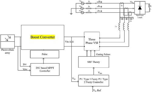
Figure depicts the distribution system series with the IT2-FLC-controlled DVR and the DES. The development of semiconductor technology is modernized and uses power converters and speed drives in the distribution network and end-user faces amplitude variation like voltage swell and sag. DVR is connected between the load and the grid to recompense the sag/swell. From the power of Extracted input of the PV of boost converter, it maintains DC-Link Voltage [Citation17]. Incremental conductance methodology can be used to extract the power from solar in maximum value. The efficacy of the distribution depends on the DVR injected amplitude voltage so that the DC-Voltage Link will be maintained with the help of SRF through IT2-FLC. For reference voltage extraction, SRF theory is used and also generates the gating pulses for DVR.
Model of Solar Photovoltaic array
Figure 1. Schematic configuration that proposed with DES.
In the productivity of acquiring benefits, the important role is in playing the design of PV array and the SPV performance. With the diode in shunt, the source current contains the SPV and by the sun ray cell form output sworn. The demand of the supremacy to meet the parallel or series has been linked in either way of number of modules.
Outline of the DC–DC boost converter
The outcome of the converter is used to maintain the DC-Voltage Link of the DVR which is depicted in Figure . With the average DC input voltage along to maintain the voltage output is to generate converter.
Figure 2. Circuit diagram of a boost converter.
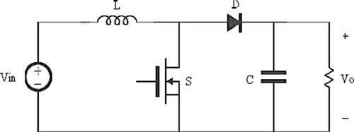
The design limitations of the boost converter are specified by Equation (1),
(1)
(1) where D = duty ratio and is stated as
and Vpv = voltage output of the solar cell. Δi is the output ripple current and fs is the frequency switching of the converter.
3. The proposed scheme for control methodology
3.1. SRF algorithm for DVR
An efficient technique is used to compensate for the swell/sag problems on the distribution side. The proposed SRF control methodology is depicted in Figure . The three-phase voltage is measured in non-linear load and it can be converted from stationary to reference.
Figure 3. Proposed SRF Control strategy.
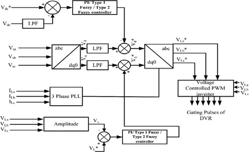
The voltage load and the voltage grid synchronization are done with the help of PLL (Phase Locked Loop). The actual voltage DC-link can be compared with the voltage that references DC-link voltage and the proposed IT2-FLC that is given based on the error value. The controller compares the actual (Vdc) with reference (Vdc*) to produce the required voltage with the loss component (Vloss in Equation 2)
(2)
(2)
3.2. INC MPPT algorithm
In photovoltaic applications, maximum power point tracking (MPPT) algorithms are used to determine the maximum power that a photovoltaic (PV) panel can output, which is dependent on two inputs: Temperature and Irradiance. To achieve the necessary voltage level on the load side, a DC–DC converter is put between the photovoltaic panel and the load. To increase the efficiency of energy conversion, the incremental conductance (INC) algorithm, the modified INC and the fuzzy logic controller (FLC) are devised and evaluated in this article. These techniques are used to track the maximum power point when controlling boost converters (MPP). Compared to traditional INC and FLC, the modified INC provides quick reaction and good performance in terms of oscillations.
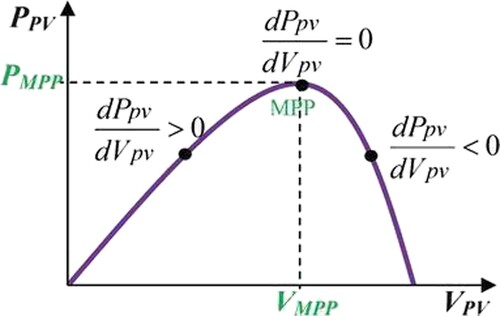
To enhance the power flow after the SPV, MPPT is employed to find the weather conditions variation (Figure ). Even in low perturbation state, proper control takes place. According to the climate conditions, the duty ratio is changed.
Figure 4. Characteristics of P–V by INC algorithm.
3.3. Voltage injection schema
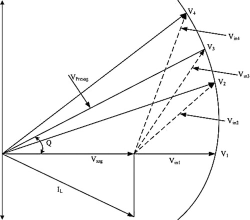
The period of sag and swell needs to compensate for the load side voltage with the desired magnitude. Therefore, DVR needs to inject the undistorted voltage load with constant magnitude in the event of sag. Figure depicts the phasor diagram of various voltage level injection schemes during sag. The voltage across the load non-linear is VLPre-sag. In the occurrence of sag, load voltage gets reduced into VSag with the phase angle of θ. To maintain a pre-sag condition, DVR needs to inject the desired magnitude voltage in the distribution. Different ways of voltage injection schemes are implemented with respect to phase angle θ. Vin1 condition states DVR injected voltage is in phase with the VSag. Vin2 condition states injected voltage remains the same, but it leads by a lesser angle. Vin3 condition states the VLPre-sag condition. Vin4 condition states with current quadrature in voltage injected. Inference from the above all conditions states that with sag voltage in phase with magnitude inject minimum with DVR.
Figure 5. Phasor diagram of various voltage level injection schemes during sag.
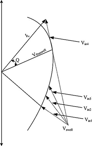
In the swell event, DVR needs voltage injection of the opposite phase to retain the load voltage continuously. Figure depicts the phasor diagram of various voltage level injection schemes during a swell. The voltage across the non-linear load is VLPre-swell. In the occurrence of swell, load voltage gets increased into VSwell with the phase angle of θ. Depending on the phase angle θ, the injected voltage by DVR can be achieved in many ways. Inference from Figure states that the VS1 offers the optimum achievable rating of DVR [Citation18].
Figure 6. Phasor diagram of various voltage level injection schemes during swell.
3.4. Interval type-2 fuzzy logic controller DVR
The accurate operation of DVR relies on the SRF control algorithm. Under the condition of dynamic, the system's stability maintains the voltage to magnitude the precise to inject it. The elements of voltage-sensing that can be helped based on the measure of voltage load and the comparator with the help of actual voltage have been compared with it and generate the output error voltage, the system stable to maintain the voltage amount that is required to produce the controller that is given with it.
To maintain the Distribution system in stable condition, a conventional PI controller is established. However, in transient conditions that cannot be implemented based on this methodology due to PI controller gain values selection. To overwhelm these conditions, Type-1 FLC is applied to generate the PI controller gain values. The actual voltage and the measured voltage load are given to the comparator to produce the error voltage. For a precise model of operation, IT1-FLC is employed to generate the outputs.
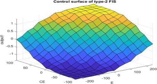
The distribution mechanism is based on the uncertainty of system stability and can handle ITI-FLC incapability. The system of high uncertainty can be handled by the system of type-2 fuzzy logic that may be constructed using the research-based fuzzy set. The system is based on the robustness to verify the FLC to maintain to establish to controlled the IT2-FC. IT2-FLC controller under the steady state the system is stable to maintain to establish it and this condition is to overwhelm the load conditions dynamic. In recent days type-2 fuzzy sets have been widely used to reduce computational costs. In this proposed work, to improve the quality the synchronous Reference Frame was to regulate the employed IT2-FLC. Figure Except for the type 1 fuzzy set, which is the same IT2-FLC that shows the block, the reducer blocks the fuzzy sets. They employed the Gaussian membership function for robust operation. With They used 49 rules to set the decrease of centre and the FIS type based on Mamdani-based fis type. Figures depict in MATLAB that implements the simulation-based IT2-FLC.
Figure 7. Block diagram of type-2 Fuzzy Logic Controller.
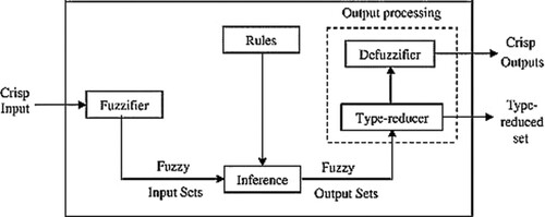
Figure 8. Gaussian MF editor of error and change in error.
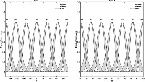
Figure 9. Gaussian MF editor of output.
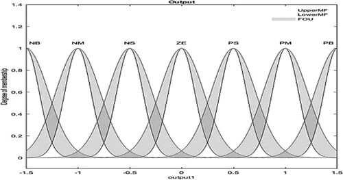
Figure 10. Surface view diagram of IT2-FLC.
4. Performance analysis of the proposed system
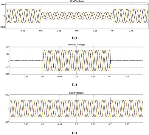
The distribution system is interconnected with the proposed DVR methodology to outcome verification. The distribution system is modelled using a three-phase 415 V, 50 Hz supply linked to 110 MVA, 0.85 PF lagging transmission line with non-linear loads. Therefore, DVR needs to inject the necessary voltage amount during the period of sag/swell. In the simulation, Line fault with capacitive load creates the sag during 0.5–0.7 s. Therefore, DVR needs to inject the necessary voltage amount concerning the voltage load. IT2-FLC is employed to control the SRF theory for generating the pulses gating of DVR. Figure (a) depicts the load voltage with sag occurrence,(b) depicts the DVR injecting the voltage during the period of sag and (c) depicts the compensated output voltage.
Figure 11. Simulation outcomes for sag event (a) load voltage with sag occurrence, (b) DVR injects the voltage during the period of sag and (c) compensated output voltage.
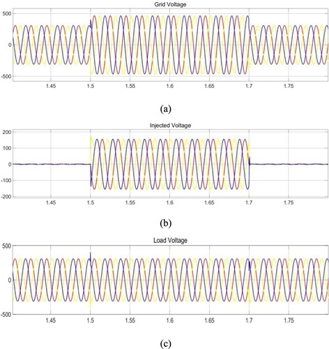
In the occurrence of an event swell, the load voltage opposes the voltage injected with DVR. So the load magnitude is constant. The swell voltage is created at 1.5–1.7 s. Figure (a) depicts the load voltage with sag occurrence, (b) depicts the DVR injecting the voltage during the period of swell and (c) depicts the compensated output voltage.
Figure 12. Simulation outcomes for swell event (a) load voltage with swell occurrence, (b) DVR injects the voltage during the period of swell and (c) compensated output voltage.
The proposed methodology can be in the distribution system to enhance the power quality. Various voltage injection schemes are demonstrated with various controllers to get better outcomes. The reference voltage of DVR estimation is done with the help of the Synchronous Reference Frame through IT2-FLC. The proposed outcome of simulation shows that the SRF- IT2-FLC results are better than the type-1 fuzzy-tuned PI and conventional PI controllers. Different scheme voltage injection of DVR has been analysed. The analysis performances based on the well voltage sag in the phase from DVR that absorption/injected in that voltage based on the evidence, by DVR the adsorbed/injected in the power can be reduced. Therefore, the proposed DVR compensate efficiently for the problems of PQ with minimal cost based on the sides of distribution and it can be used as an economical alternative UPS application on the Distribution side. Further, other PQ problems are to be extended with this work (Figure and and Tables ).
Figure 13. Controller performance comparison during voltage sag.
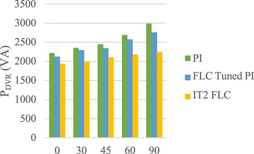
Figure 14. Controller performance comparison during Voltage swell.
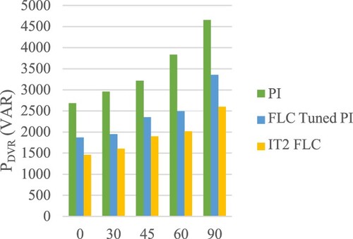
Table 1. Planned DVR outcomes for voltage sag.
Table 2. Performance evaluation of voltage sag.
Table 3. Performance evaluation of voltage swell.
5. Experimental outcomes
Simulation outcomes are compared with the smaller rating of the prototype model [Citation19]. The prototype model of DVR is depicted in Figure . Experimentation was carried out in a 100-V AC-connected source to the power electronic load. Figure depicts the voltage sag at phase A and inverter output voltage. The voltage gets reduced during the voltage of sag to 58.7 V. Figure depicts the compensated output voltage (Table ).
Figure 15. Prototype model of DVR.
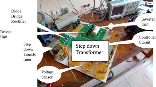
Figure 16. Inverter output voltage and load voltage with sag occurrence.
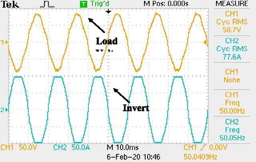
Figure 17. Compensated load voltage.
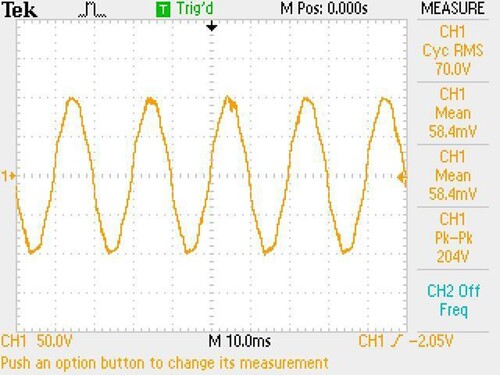
Table 4. Comparison of proposed work with existing work.
The figure in Results section illustrates how the INC approaches can both achieve the highest level of power point tracking. The simulation results of the INC, MPPT techniques, however, can reach the maximum power point tracking more quickly, with less oscillation, and with more tracking precision than the MPPT techniques. Both irradiance and temperature under different power stability at maximum I running system that makes photovoltaic in order, an evaluation of some of the most prominent MPPT techniques has been provided and analysed in this study. The traditional incremental conductance INC, the approach based on SRF-IT2-FLC achieves superior results than type-1 fuzzy-tuned PI and conventional PI controllers have been examined. Each algorithm has been created, examined and put into practice.
6. Conclusion
The suggested methodology has the potential to improve the distribution system's power quality.To achieve better results, multiple voltage injection strategies are tested with various controllers. The frame references Synchronous through IT2-FLC are used to calculate the reference voltage for the DVR estimate. According to the findings of the simulation, the proposed SRF-IT2-FLC achieves superior results than type-1 fuzzy-tuned PI and conventional PI controllers. The analysis of several DVR-injected voltage strategies has been done. According to the analysing performance, it is clear that DVR injected voltage and absorption are in phase with the voltage sag and swell, by DVR the absorbed and the injected were powerless being with the result. As a result, the suggested DVR may effectively and cheaply correct PQ issues on the distribution side, and it can be utilized as a viable alternative UPS application there. Additionally, other PQ issues can be addressed by this study.
Disclosure statement
No potential conflict of interest was reported by the author(s).
References
- Bollen M. Understanding power quality problems. In Voltage sags and Interruptions. Piscataway, NJ, USA: IEEE press; 2000.
- Mansoor M, Mariun N, Toudeshki A, et al. Innovating problem solving in power quality devices: A survey based on dynamic voltage restorer case (DVR). Renewable Sustainable Energy Rev. 2017;70:1207–1216. doi:10.1016/j.rser.2016.12.022.
- Kang T, Choi S, Morsy AS, et al. Series voltage regulator for a distribution transformer to compensate voltage Sag/swell. IEEE Trans Ind Electron. 2017 Jun;64(6):4501–4510. doi:10.1109/TIE.2017.2668982.
- Hafezi H, Faranda R. Dynamic voltage conditioner: A New concept for smart Low-voltage distribution systems. IEEE Trans Power Electron. 2018;33(9):7582–7590. doi:10.1109/tpel.2017.2772845.
- Farhadi-Kangarlu M, Babaei E, Blaabjerg F. A comprehensive review of dynamic voltage restorers. Int J Electr Power Energy Syst. 2017;92:136–155. doi:10.1016/j.ijepes.2017.04.013.
- Sathik Basha A, Ramasamy M. Design of Z-source inverter-based dynamic voltage restorer circuitry with R-SOGI control scheme for enrichment of power quality. J Circuits Syst Comput . 2021;30:2150195. doi:10.1142/s0218126621501954.
- Ray P, Das S, Mohanty A. Fuzzy-Controller-Designed-PV-Based custom power device for power quality enhancement. IEEE Trans Energy Convers. 2019;34(1):405–414. doi:10.1109/tec.2018.2880593.
- Sangwongwanich A, Blaabjerg F. Mitigation of interharmonics in PV systems With maximum power point tracking modification. IEEE Trans Power Electron. 2019 Sept;34(9):8279–8282. doi:10.1109/TPEL.2019.2902880.
- Kordestani M, Mirzaee A, Safavi AA, et al. Maximum power point tracker (MPPT) for photovoltaic power systems-A systematic literature review. 2018 European Control Conference (ECC). 2018: 40–45. doi:10.23919/ECC.2018.8550117.
- Polade G, Kulkarni P. Implementation of power electronic transformer based dynamic voltage restorer (DVR) to improve power quality At distribution side (load). Int J Modern Trends Eng Res. 2017;4(6):150–157. doi:10.21884/ijmter.2017.4196.qmzln.
- Pal R, Gupta S. Topologies and control strategies implicated in dynamic voltage restorer (DVR) for power quality improvement. Iranian J Sci Technol Trans ElectEng. 2019;44(2):581–603. doi:10.1007/s40998-019-00287-3.
- Zadeh L. The concept of a linguistic variable and its application to approximate reasoning—II. Inf Sci (Ny). 1975;8(4):301–357. doi:10.1016/0020-0255(75)90046-8.
- Wu D. On the fundamental differences between interval type-2 and type-1 fuzzy logic controllers. IEEE Trans Fuzzy Syst. 2012;20(5):832–848. doi:10.1109/tfuzz.2012.2186818.
- El-Bardini M, El-Nagar A. Direct adaptive interval type-2 fuzzy logic controller for the multivariable anaesthesia system. Ain Shams Eng J. 2011;2(3-4):149–160. doi:10.1016/j.asej.2011.08.001.
- Kala Rathi M, Rathina Prabha N. Interval type-2 fuzzy logic controller-based multi-level shunt active power line conditioner for harmonic mitigation. Int J Fuzzy Syst. 2018;21(1):104–114. doi:10.1007/s40815-018-0547-7.
- DaneshvarDehnavi S, Negri C, Bayne S, et al. Dynamic voltage restorer (DVR) with a novel robust control strategy. ISA Trans. 2021. doi:10.1016/j.isatra.2021.04.010.
- Mr. Kamaraja AS, Dr. Rathina Prabha N. ANFIS controller of PV assisted custom power device for improving power quality. IJAST. 2020 Mar;29(3):10580.
- Bhavani R, Rathina Prabha N. Simulation of reduced rating dynamic voltage restorer using SRF–ANFIS controller. Int J Fuzzy Syst. 2018;20(6):1808–1820. doi:10.1007/s40815-018-0491-6.
- Savrun M, Köroğlu T, Tan A, et al. Isolated H- bridge DC–DC converter integrated transformerless DVR for power quality improvement. IET Power Electron. 2020;13(5):920–926. doi:10.1049/iet-pel.2019.0687.