
 ?Mathematical formulae have been encoded as MathML and are displayed in this HTML version using MathJax in order to improve their display. Uncheck the box to turn MathJax off. This feature requires Javascript. Click on a formula to zoom.
Abstract
In the case of hybrid sustainable energy power systems made up of Solar Photovoltaic, wind, and an integrated energy storing system connected to a grid network, this research suggests a better control technique for optimal Power Quality improvement. The Unified Power Quality Conditioner with Real and Reactive Power are built-in with the proposed Hybrid Sustainable Energy Systems, and they include Type-1 and Interval Type-2 Fuzzy-based controllers. The main objective is to simultaneously control voltages while minimizing power losses and Total Harmonic Distortion. The Unified Power Quality Conditioner is utilized to reduce Power Quality concerns such as sag, swell, real power, reactive power, and harmonic distortion related to voltage/current by utilizing a proposed controller. The innovative method is displayed in various ways, such as simultaneous PQ replenishment and RES power injections, RESP > 0, and RESP = 0. In addition, the recommended methodology outperforms earlier literature approaches, such as PID controllers. The system is built on the MATLAB Simulink platform, where various performance studies are conducted.
1. Introduction
The advantages of using photovoltaic solar energy for rural electrification are rapidly growing. Farmers depend on a solar photovoltaic generation because of its continuous operation, simplicity in construction, low maintenance, and cheaper fuel cost. To supply continuous electricity, governments and charitable organizations are setting up or helping to build photovoltaic systems in isolated rural locations. Because they enable users to lower their monthly energy costs while supporting utilities during peak loads, these programmes are quite popular in cities.
To make the possible automated operating condition of multi-microgrids through a Smart Transformer, the dc interconnection offered to incorporate a nearby energy storing system (ESS) and the versatility to function its energy conversions levels in a grid forming (GFM) or grid-following (GFL) modes are essential [Citation1]. The effectiveness of grid-integrated solar photovoltaic array systems is improved with the development of revolutionary non-linear regression least squares regression-based controller parameters. The devised method is physically verified in various challenging circumstances, including over-voltage, under-voltage, altered grid voltages, changeable load variation, and different solar radiation exposure fluctuation conditions.
Photovoltaic feed-forward units are incorporated into the current controller to reduce fluctuations in grid currents caused by changes in the demand and generation of solar energy. A single-stage solar energy conversion system (SECS) is employed to connect the voltage source to the grids. The voltage source converters (VSC) dc-linking capacitance and PV module are directly connected [Citation2].
A significant weakness in the sliding-mode controller design can be seen in designing the switching surface in a stochastic process. The effectiveness in dynamic settings declines if the substrate is not appropriately designed. As a result, this control approach is useless under dynamic circumstances [Citation3].
Whenever droop-controlled grid-integrated microgrids are linked to deformed grids, a modulation technique for enhancing power quality and reducing the harmonics of grid-connected power supplies is used [Citation4,Citation5] implements FLC-based controller parameters that outperform a PI control system in consideration of convergence speed under transitory situations. It provides the advantage of seamless machinery rate management by taking into account the control algorithm and fuzzy membership in a suitable manner. Under odd conditions of inconsistent `solar energy, dc offsets, distortions in the grid voltages, imbalance in the three-phase Point of Common Interactions (PCI) voltages, voltage instability, and swells, the voltage source converter control method creates the gating signals and enhances the PQ [Citation6,Citation7]. The Inductor Power Filtration (IPF) technique put forth by Li and Luo could accomplish harmonics reduction close to the harmonics inputs and reduce the detrimental effects of oscillations on the transformers [Citation8].
The electric vehicle aggregators serve as a mediation control system between the grids and the automobiles and permit the grid pattern to govern the charging and discharging operations. This assists the grid pattern in regulating loads under different loading underbalanced scenarios, lowering Harmonic distortion, and improving voltage stability. There are numerous grid-connected Electric vehicle systems optimizations and control strategies [Citation9,Citation10]. The charging station functioning is shown in Islanded Modes (IM) and grid-integrated modes in order to maximize operating effectiveness. Additionally, a centralized controller is created to enable active filtration, reactive power compensation, vehicular-to-home power transmission, and four-quadrant operations (V2G/G2 V) [Citation11]. The fixed integrators and differentiation terms restrict numerically ordered filtering [Citation12].
A multipurpose grid-connected inverter is used in this [Citation13] to deliver the auxiliary service of power factor adjustment at the grid side concurrently with the infusion of energy produced by a renewable source. The suggested method compensates for Power quality disturbances by using the power system factor as an essential parameter that controls the multipurpose inverters compensating actions. Consequently, the technique guarantees that the degree of correction is precisely determined by an intended PQ rate at the utility grid, as represented by a power factor [Citation13].
A voltage-controlled DSTATCOM-based control method for minimum voltage distribution system that employs a 3-phase 4-wire VSI including an LC low-pass output filter [Citation14]. The operational concepts and controlling techniques of a voltage regulator DSTATCOM were given. The suggested control scheme also includes two loops: the notion of minimal power point tracking and the frequencies loop [Citation15,Citation16]. Furthermore, by including solar Photovoltaic and wind feed-forward factors in the control strategy, the dynamics of the developed framework are greatly enhanced [Citation17].
Multilevel conversions can be utilized to link wind generators to the grids; the controller must be ready to send an imbalanced power to the system while exacerbating the converter’s DC bus imbalances. The novel strategy involves imbalanced reactive current injections from the converters linking the wind generator to the system [Citation18].
Whenever the system is integrated into dual PV-wind systems, the DVR’s capacity to reduce voltage fluctuations, limit its effects on the absolute reliability of the transmission and distribution systems, and increase LVRT capabilities. A DVR based on fuzzy controls and phase correction is devised and tested during different fault scenarios, including fault conditions and voltage sags [Citation19].
Power quality disruptions caused by grid-connected renewables in power system environments to specific practical systems are examined using IoT & 5G networks. The three essential processes in Power quality disturbances identification and tracking are thoroughly outlined using diverse methodologies given by authors in the literature: pre-processing, extraction of features, and categorization [Citation20]. The greater the inactive components, the smaller the output frequencies. Such constraints can be bypassed using the Maximum Constant Boost Control technique. Furthermore, the ST duty cycle remains static in the Maximum Constant Boost Control technique, resulting in broader grid current ranges and reduced ripples [Citation21]. As a result, the Unit Vector Templates with Maximum Constant Boost Control could identify voltage fluctuations correctly, insert the voltage output with reduced harmonic, and mitigate them effectively [Citation22]. To correct the voltage unbalance, a power semiconductor connection between the input and output is proposed; the goal is to offer voltage output management while also increasing system reliability. The suggested approach is unique because it employs multilayer inverters to provide a twofold benefit. The phrase “multilevel” refers to three-level conversions. The semiconductors circuits’ synchronization combines numerous Voltage levels to produce high output voltages [Citation23,Citation24]. Among the most often key challenges as per the literature study:
The distribution Static compensator voltage requirements have not been completed correctly.
Active power filters in series are exclusively utilized for reduced power purposes.
Efficiency becomes lower when multilevel conversions can be used due to conductivity loss.
This study’s main focus is on preventing power quality issues in HSES systems brought on by voltage or current issues, non-linear loads, unbalanced loads, interruptions, and Harmonic distortion reductions. These problems are successfully mitigated by the proposed Type-1 Fuzzy and Interval Type-2 Fuzzy Controller and UPQC devices. The key influence of the article is as tracks:
Photovoltaic, wind, and batteries are combined to create a hybrid source that can be used when the other resources aren’t available. Additionally, a battery is used to store extra energy produced by resources that could be used to better meet demand in times of extreme ecological disruption.
The power grid, a non-linear load, and an unbalanced load are all connected to the hybrid source, and both can be connected at PCC. The integrated model can result in distortions and unbalances for distorted input voltages. Using a Type-1 fuzzy and Interval Type-2 fuzzy controller can help to lessen this impact on the system’s consistency and reliability.
The proposed control method is developed and assessed for linking imbalanced and non-linear loads at PCC.
The article is structured in the following manner: Section 2 imparts an explanation of the proposed system design. This section reviews the UPQC in detail and explores the computational models of the prototype architecture’s hybrid source components. The proposed strategy is described in Section 3, along with a framework for control. The Controller settings and the controlling techniques are defined in Section 4. Results and Comparative analysis with various conditions are thoroughly explained in Section 5. Lastly, the Conclusions and Future scope of the article are exposed in Section 6.
2. Design of proposal HSES system
As a result of increased industrialization, its service has also faced actual standard modifications due to the inclusion of excess power requirements inside the network. The critical energy demands in today’s modern electrical network cannot be satisfied by conventional generating techniques, which create new security and power stabilization problems. Additionally, throughout the last several decades, a significant number of toxins have been released by conventional generating methods. Utilizing local and sustainable energy sources helps to reduce grid problems while producing a sizable amount of power to replace load demands on that power system. The hybrid system aims to improve system reliability and performance, which makes it as most powerful technology. Voltage stability problems develop as a result of HSES modification in an integrated grid system. To address issues with overvoltage, power losses, and voltage disruptions, the HSES uses UPQC (real and reactive power). Design Specifications of the entire system are exposed in Table .
The usage of UPQC systems reduces problems of power quality. The UPQC model’s related to actual and reactive power management theory. A photovoltaic module plus grid-connected wind energy makes up the HSES. To satisfy load requirements and endure severe climatic factors like solar and wind, the battery is composed of HSES. But, non-linear loads and unbalanced demand, when coupled with grid-linked HSES systems, are leading to an increase in power quality difficulties. So as a result, Reactive power instability and raised voltage uncertainty occur.
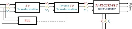
As a consequence, in order to deliver excellent services, power quality issues should be avoided, and it can be done only with the use of Converters. The UPQC might be the best option for improving grid-connected HSES’s ability to manage voltage while simultaneously handling power quality concerns. The development of the Control scheme improves the suitable execution of UPQC with the assistance of T1-FLC and IT2-FLC. A schematic diagram of the suggested system is shown in Figure . HSES are used to meet the demands for loads globally.
Figure 1. Schematic representation of the proposed System.
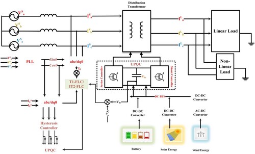
Batteries are used to store surplus power produced by the sun and wind, which can be utilized in emergency situations. Energy quality issues with the grid interfacing HSES system present a crucial difficulty in ensuring reliability. Power quality issues within the HSES on the system are a result of abnormal situations, non-linear demand, and critical loading. Grid-connecting HSES systems must overcome power quality difficulties in order to operate properly. The UPQC is equipped with grid-connected HSES linked-up technology that compensates for PQ disturbance, non-linear, unbalanced load, High voltage, voltage dips, and non-linear load. To reduce PQ difficulties, the UPQC uses a series and parallel filer control scheme. Filters offer the best gain configurations for adding the power required to overcome PQ challenges when utilizing the controller.
2.1. Solar PV modelling
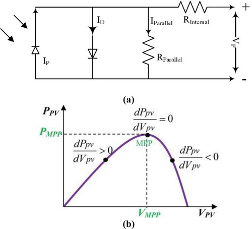
In terms of robustness with the non-rotating device, more durability, good efficacy, and minimal maintenance among the many power sources, Solar Photo voltaic is the best replacement option for producing power from Photo voltaic without causing climate changes. Cells in the Photo voltaic system are integrated with series to provide the required voltage. The Photovoltaic planes of the ultimate voltages are derived by combining the terminating voltages and the current. The corresponding Equivalent solar module model is figured in Figure (a). The specifications of the Solar panel's current and output voltages are calculated using Equations (Equation1(2)
(2) ) and (Equation2
(3)
(3) ).
Figure 2. (a) Equivalent solar module model (b) Characteristics curve of P-V by INC technique.
2.2. Modelling of the wind system
When certain nominal circumstances were met, the wind generator generated electrical output based on the direction of the wind. The wind velocity for that wind generator is related to equation (Equation4(5)
(5) ).
(4)
(4)
denotes wind turbines at cutting voltages, VR denotes baseline wind velocity, V(t) denotes wind velocity at time t,
denotes windmill cutoff speed,
denotes windmill cut-in velocity, and
denotes wind generates peak power. The network uses solar and wind power systems to control peak load. Batteries are joined to the system when the produced power capacity exceeds HSES’s ability to adjust.
2.3. Modelling of battery storage systems
The battery provides the necessary power when the HSES’s output is insufficient. When a system requires electricity, the battery capacity is estimated and analyzed using the standard autonomy day, which is shown in the upcoming equation (Equation5(6)
(6) ).
(5)
(5) Where
the typical number of hours a battery can produce power towards support maximum demand.
Stands for depth of discharge rate,
for inverter effectiveness,
for battery performance, and
for desired power. The batteries have the capacity to supply excess energy generated via additional sustainable energy resources. In order to calculate storage capacity, apply equation (Equation6
(7)
(7) ).
(6)
(6)
appears to represent the system loading requirement, while B is the storing capacity. An important factor in relation to increased power production and power shortage in HSES is a battery’s state of charge (SOC). The proposed design method might be affected by power quality problems like dip, swell, voltage distortion, etc. Implementation of the UPQC unit inside the HSES systems has solved the network’s power system problems, which should be addressed to improve system reliability. The UPQC modelling is demonstrated in the following chapter.
2.4. UPQC specifications in the suggested system
Current electronic-based power conversion systems can assist in developing the efficiency of the electric grid, making it a viable alternative. In this study, a UPQC method is chosen to reduce the voltage stability of the HSES structure. PQ issues will be resolved with this device. There are numerous facts and methods available to address power quality problems. The UPQC can also be used to address problems with voltages and current, such as minimum voltage, high voltage, imbalance, transient, and distortion. Parallel and series real Power Filters, as well as direct current connection capacitors, are the two main types of Voltage Source Inverters used by the UPQC. The essential element which controls the voltages between two filtering is the DC-linking capacitors. An illustration of the UPQC configuration can be found in Figure . A UPQC’s vector structure, containing imbalanced voltage correction, is shown in Figure b. The power grid of the controlling devices could be allocated into a number of components, including the generator, series, and shunt active filters. (7) And (8) describe Kirchhoff’s equation, which is frequently utilized to represent the energy source,
(7)
(7)
(8)
(8) Figure a, with the general circuit model, it is shown that
represents the current at the output side of parallel active filters,
denotes the output voltage of series active filters,
represents the current at the load,
represents the line current,
represents the supply voltage,
represents the line inductance,
represents the electrical transmission resistor, and s in the superscript represents the a, b, and c. The analogous circuits of the UPQC are shown in Figure b. Series and shunt active filters control the supply current and output voltage all over the UPQC system.
Figure 3. Description of the UPQC configuration.
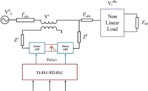
Figure 4. (a) General equivalent (b) UPQC equivalent (c) UPQC voltage compensation vector chart.
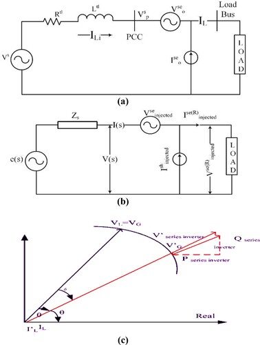
When power demands arise in the power grid, the series and shunt active filter the O/p at the proper voltage. Input and load currents are usually represented by (R) and I(s).
and
denotes the injecting current and voltage of the shunt and series active filter, respectively. The injecting voltages of such a set of real filters, represented by
, serves as the reference voltage output (R). As
represents the demand’s power factor, while k represents the input voltage factor’s variance. The ratio of the reference voltages to the difference in voltages between the input and the reference is calculated using equation (Equation9
(10)
(10) ). The voltage compensation’s UPQC vector chart is shown in Figure c. The cascaded inverter provides a negative voltage V0 into the grids to eliminate any voltage spikes VG that may be present in the system.
(9)
(9) Equation (Equation9
(10)
(10) ) could be influenced by using equation (Equation10
(11)
(11) ),
(10)
(10) UPQC layouts got rid of the losses. The power demands of loads and power O/p were based on the PCC source. The subsequent equation indicates the current on the PCC side (11)
(11)
(11) Within the UPQC, the evident power of a series and parallel active filter is expressed as (12) and (13),
(12)
(12)
(13)
(13) Where
=
I(s);
=
I (s) cos(s);.
appears to be the active power of the series filter and
is the reactive power of a series filter,
appears to be the difference between the load current, the supply current, the load harmonic current, and the reactive current. Active power filters of the UPQC device are controlled by a controller with a T1-FLC and IT2-FLC basis. Further, the controllers are used to improve system reliability by addressing power quality issues.
3. The suggested controller approach
Currently, there has been a rise in the demand for electricity from the distributing system as an outcome of quickening industrialization and development. The HSES is chosen to mollify the energy desires of the distribution system while reducing environmental problems. The HSES provides the necessary electricity without reducing the hazards associated with climatic changes or damaging greenhouse gas emissions. Grid-connected systems that utilize the HSES dilemma raise reliability and energy management issues. In order to retain the system’s dependability and adaptability, the issue of efficiency must be addressed. Only the UPQC system should be used to address the system reliability concern.
The UPQC computer speed is increased by integrating an excellent control approach into the system. Utilizing UPQC and the recommended controllers, the O/p voltages of HSES are improved when connected to a power grid. The UPQC structure has two controllers: a parallel and a series APF. The HSES method for managing PQ concerns is by using control mechanisms. The series and the shunt active filter are presented in more detail in the upcoming chapter. Additionally, both series and shunt active filters are fully covered in this chapter.
3.1. Series active filters controller method
The Controllers are shown in Figure , which is a diagrammatic representation of a series active filter. The reference voltage is measured initially. The 3 phase voltages are measured, and then they are transformed into d-q axes utilizing the dq transformations technique. A power filter is widely used to assess the UPQC and address issues with the quality of the power within the system. Equations (Equation14(15)
(15) ) and (Equation15
(16)
(16) ) illustrate the arithmetic solution of the dq transition process from 3-phase voltage.
(14)
(14) where,
Wherein
stands for quadrature axes voltages,
denotes direct axes voltages,
,
, and
denote three-phase voltages. Direct voltage and an AC component voltage are displayed for the values on the d-axis. The Low Pass Filter, which is represented mathematically as being able to level the d-axis voltages (15),
(15)
(15) Here,
stands for direct voltage and
for alternate voltage. The voltage is then split into three parts as follows: (16),
(16)
(16) The three-phase reference voltages
,
, and
are used in this sentence. The control signal is calculated and altered by the proposed controllers.
Figure 5. Diagrammatic representation for series active filter.
3.2. Approaches to shunt active filter control
The recommended control strategy is used to regulate the shunt active filter in Figure . As shown in equations (Equation17(18)
(18) ) and (Equation18
(19)
(19) ), the three-phase current and voltage are first transformed into equation (Equation18
(19)
(19) ). Where the three-phase load currents are represented in
,
, and
. The currents
,
are considered to be phase-neutral current. While
,
stands for phase neutral voltages,
, and
stand for three-phase source voltages. The phase-neutral voltage and load circumstances are used to calculate the true and unrecognized power of the impulse responses. Equations are used to compute the active (P) and reactive(Q) power within the shunt active filter by equation (Equation19
(20)
(20) ).
(17)
(17)
(18)
(18)
(19)
(19)
Figure 6. Diagrammatic representation of active shunt filter.
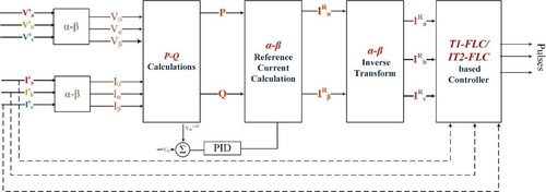
Following that, an equation (Equation20(21)
(21) ) is used to compute the reference currents.
(20)
(20) The reference current of the shunt active filter is
,
and
. The fault current must be modified using the controller settings and the T1-FLC and IT2-FLC methods after being computed depending on the reference signals. Based on the system fault data, the ideal pulses were selected and produced in the shunt active filters.
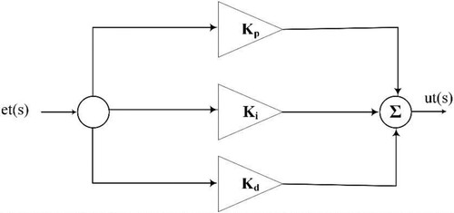
3.3. PID controller
The active (P) and reactive (Q) power on the grid is monitored using a sensing kit and sent into the comparator blocks. The comparator measures the average and reference power and sends the results to the controllers to generate switching pulses. Ultimately, the controller provides the necessary power during injection and absorption. In order to achieve a higher output to regulate the HSES systems, the Control scheme would be utilized to decrease error voltages and currents by eliminating error signals, eliminating undershoot and overshoot difficulties, and speeding up the controller responding time. The devices are additionally accelerated, their damping is reduced, and their resistance to parameter change is greatly increased by the Control system.
(21)
(21) Equation (Equation21
(22)
(22) ) is defined as follows: whereas
is the Controller output,
is the HSES error signal, and
is the PID controller transfer function. The mathematical modelling of a PID controller can be expressed in equation (22). The PID controller design is shown in Figure [Citation25–28]. The abbreviations
stands for proportional variables,
for integral variables,
for derivative variables, and
stands for error signal produced by shunt and series active filters. The error is calculated when there are diverging loads by comparing the reference and original value. Both the T1-FLC and IT2-FLC approaches are used to provide the optimal signals that are perfect for the PID.
(22)
(22)
Figure 7. PID controller design.
4. Proposed control methodologies
4.1. Type-1 fuzzy logic controller
In 1965, Professor Zadeh invented the fractional member function, which is an advanced form of the basic membership function. To correct the incorrect forecasts, the T1-FLC is used. The implementation of the Gaussian membership function is made possible by its ease of use and superior performance [Citation20].
Here, the FLC is used with one output function and 2 variables (error and error variation). The Fuzzy Controller includes components for Fuzzification, fuzzy inference systems (FIS), number of rules, and defuzzification. The Fuzzified unit converts the input variables from the crisp input into a fuzzy rule. The rules base for the T1-FLC is exposed in Table . A Mamdani-based FIS type and centre of reduction sets are used with 49 restrictions. The Design of a T1-FLC is shown in Figure . The simulation-based T1-FLC in Matlab is displayed in Figures and .
Figure 8. Type-1 Fuzzy Logic Controller Illustration.
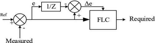
Figure 9. Errors and modifications in error editors using Gaussian MF.
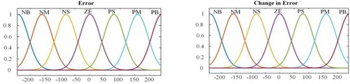
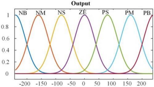
Figure 10. Gaussian MF output editor.
4.2. Interval type-2 fuzzy logic controller
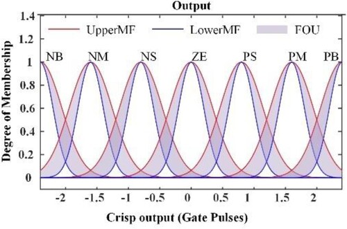
T1-FLC is unable to keep the system steady because of the grid-integrated network’s clear unpredictable nature. To deal with circumstances with a lot of uncertainty, experts are developing type 2 fuzzy logic circuits using fuzzy set theory. For a further degree of freedom, type-2 fuzzy logic systems (FLS) use 3-dimensional fuzzy sets that include the footprint of uncertainty (FOU). The system’s robustness may be verified by comparison to the normative T1-FLC [Citation21–23]. An IT2-FLC controller is developed to address these issues and maintain system stability in both steady-state and dynamic load settings. Type 2 fuzzy sets have gained popularity recently as a means of lowering computation expenses.
Figure shows the illustrative diagrams of IT2-FLC that is similar to type 1 Fuzzification, with the exception of the reduction blocks. Gaussian membership parameters are cast off for stable methods. A Mamdani-based FIS type and Centre of reductions groups are used with 49 limitations. Figures and display the Matlab simulation-based IT2-FLC. The inverter must provide a certain amount of reactive power in order to increase stability under dynamic conditions. As a consequence, the capacity of the grid is described using various sensors, much like how larger powers are represented using a comparator, and the error O/p is provided to the controller to generate the proper gating pulses.
Figure 11. Diagrammatic Representation of Type 2 Fuzzy Logic Controller.
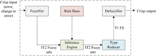
Figure 12. Gaussian MF error and variation in error editor.
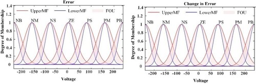
Figure 13. Output from the Gaussian MF editor.
5. Results and discussion
This section assesses the efficiency of the suggested strategy. The suggested method aims to resolve grid-related PQ problems in HSES. By fixing PQ problems, the main goal is to increase system reliability. Section 2 examined the drawbacks of organized procedures. As a result, the proposed controllers and UPQC aid in boosting power efficiency. By integrating UPQC solely with an established controller, the suggested system would boost stableness and voltages with current demands in network interface HSES. To reduce PQ problems in the HSES system, the proposed controllers are used with the UPQC devices. Both in the presence and absence of the system PQ concerns, the variables are analyzed. The outcomes and the suggested strategy were employed in MATLAB Simulink. The proposed method is contrasted with existing PID, T1-FLC, and IT2-FLC controllers-based controllers. At simulated condition, THD values are taken at T1 = 0 sec, T2 = 0.1 sec, T3 = 0.22 sec, and T4 = 0.3 sec for mode 1 & mode 2 are displayed in Table . The production and confirmation of power quality problems include distortion, voltage fluctuations, sagging, and swells. Power quality issues are resolved with UPQC devices. By providing an appropriate pulse of series and shunt active filters, the suggested controllers tackle the power quality issues in the best possible way. The UPQC can provide the capability required to address Power quality issues and make system capacity adjustments. In the UPQC layout, the dc-linking capacitance is utilized to supply vital energy to minimize Power quality issues in the proposed HSES systems. Electricity can be produced using solar and wind technology to satisfy the primary source load demands of the structure. The wind and Photovoltaic may be precious by ecological conditions that may be lessened by implementing the Maximum PowerPoint method into the systems. In order to handle the peak load and reduce the issue with the power quality system, the generated power has been employed in the UPQC systems. A loading device that connects to the grids is used in connection with the UPQC technology. The assessment of a proposed theoretical framework under three system fault conditions, such as sag, high voltage, voltage disturbances, and distortion value.
Table 1. Summary of mode 1 and mode 2 process simulated results.
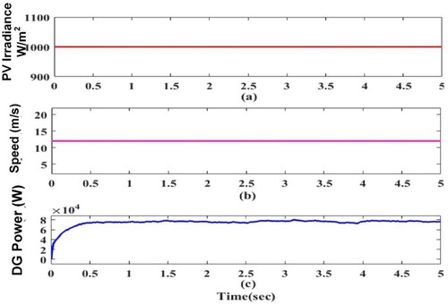
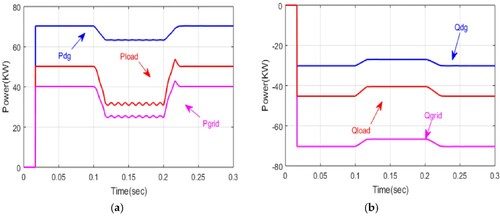
The recommended HSES approach makes electricity travel to the point of connection possible in this mode of operation. The inverters that act as the grid’s link are used to distribute energy from the sustainable source to the PCC in order to improve the PQ along the line. PCC is connected to the series resistor–inductor load of uncontrolled diode rectifiers, which is a general non-linear load. Both active and reactive electricity is provided by renewable sources to meet nearby needs, with any realistic excess power being transmitted to the grid. Since the grid voltage is not linear, combining the input voltage’s fifth harmonic yields a total harmonic distortion of 20.94%. Mode 1-PQ improvement with RES power injection (RESP > 0) condition outcomes of active power of Pload, Pgrid, Pdg is depicted in Figure (a). The reactive power Qdg, Qgrid, and Qload outcomes of the Mode 2 is depicted in Figure (b). The THD values of the varying factors are highlighted in the Table scenario. Figure shows the solar radiation, wind velocity, and DG output of Mode1.
Figure 14. (a) Active (P) power in kW (b) Reactive (Q) power in kVAR.
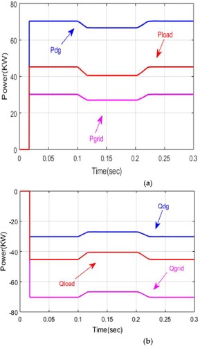
Figure 15. (a) Solar Irradiation (b) Wind Velocity (c) DG Power.
5.1. Mode-1 PQ improvement with RES power injection (RESP > 0)
5.2. Mode-2 PQ improvement (RESP = 0)
In this scenario, a grid link called an inverter serves as a Shunt active filter. In this circumstance, the inverters only use a small amount of actual grid capacity to reduce loss and enhance DC bus voltage. Alternatively, the inverters deliver the demand for actual and reactive power electricity. The real power Pload, Pgrid, and Pdg, as well as the reactive power Qload, Qgrid, and Qdg, are shown in Figure (a) and (b). The grid supplies real electricity, while the inverters supply all of the reactive power. Dynamic features are examined in Cases I and II.
Figure 16. (a) Active (P) power in kW (b) Reactive (Q) power in kVAR.
5.3. Case1: conditions for non-linear load variation
It is possible to examine the dynamic characteristics of moment voltage sagging by including non-linear load fluctuations. In this scenario, a bridge rectifier using resistance inductive load condition appears to be a non-linear demand. When t = 0.1 s, an extra resistor–inductor load is added to the existing load and then removed by 0.22 s. The current is amplified from 54.95 A to 61.98 A as a result. The transient response of a voltage at the PCC, a load current, a grid current, and an inverters terminal current is shown in Figure . Grid side Total harmonic distortion falls from 24.32% before compensating to 19.92% after compensatory, with load current harmonic distortion falling to 19.01% and 19.02% of voltage interruption brought on by an increase in PCC.
Figure 17. Point of common coupling voltage Vs, Grid current Is, Load current IL, Inverter Terminal current Ic.
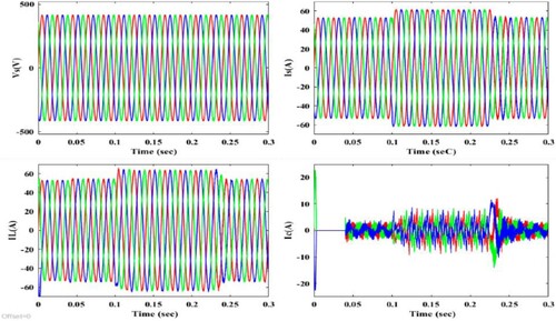
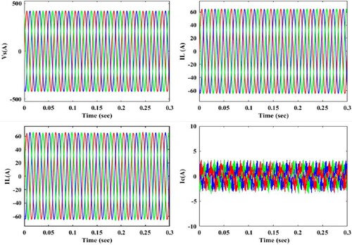
5.4. Case2: unbalanced non-linear load conditions
A bridge rectifier and a resistive, inductive load are commonly coupled to the PCC as an imbalanced load. From t = 0.1 s to 0.22 s, a single-phase resistive, inductive load is associated between these 2 stages in this circuit. Figure demonstrates that even when unbalanced loads are coupled to the PCC, the grid current, load current, and inverter terminal current are all suited. When t = 0.1 s to 0.22 s, the THD of the load current is 19.02, 25.35, and 17.04 percent, whereas it is 19.98, 11.33, and 17.31 percent for the harmonic distortion of the load current. The system could be controlled by reactive and nonlinear load current components.
Figure 18. Point of common coupling voltage Vs, Grid current Is, Load current IL, Inverter Terminal current Ic.
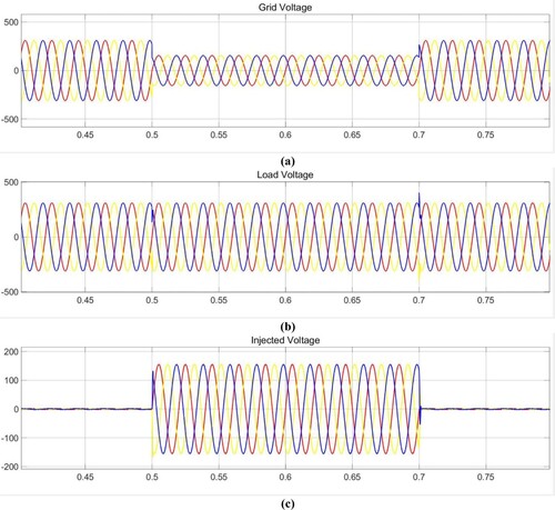
5.5. Case3: conditions for voltage sagging
In this phase, a disturbance is introduced to cause sagging in the HSES systems. For this system to run linearly and consistently, the voltage sag must be fixed. The UPQC is made to estimate the required capacity to meet load needs while minimizing Power quality problems. Figure shows the injecting voltage, the grid voltage, and the load voltage. Voltage injected by the recommended controller is used to address the PQ problems. Voltage balance in UPQC is achieved by all series and shunt active filters.
Figure 19. Investigation of Voltage sag situations (a) Grid Voltage (b) Load Voltage (c) Injected Voltage.
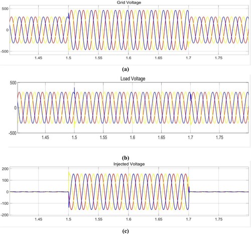
5.6. Case 4: condition of voltage swelling
Enhanced voltage is referred to as swell when compared to the reference voltage. System flaws lead to the observation of the swell condition. The swell needs to be resolved in order to increase the system’s dependability. A 480 V voltage surge was observed between t = 1.5 and 1.7 s and was corrected using UPQC equipment. The voltage swell situation during grid voltage, load voltage and injected voltage are illustrated in Figure . In this situation, the dc-link capacitors are utilized with proposed controllers, which are primarily used to calculate the absolute error, manage load consumption and minimize power quality problems.
Figure 20. Investigation of Voltage swell situations (a) Grid Voltage (b) Load Voltage (c) Injected Voltage.
5.7. Comparison evaluation
The optimum THD value for the proposed IT2-FLC is depicted in Figure . In an HSES-connected grid system, the T1-FLC and IT2-FLC controllers’ ability to mitigate distortion, asymmetric loading, imbalance loading, drooping, and swelling are all explored. Figures and shows the P and Q power comparison of conventional PID with proposed controller techniques such as T1-FLC and IT2-FLC. According to Table , the total distortion reduction has also been compared between before and After UPQC compensation in accordance with the best standard while meeting the demands of IEEE519. According to the study’s findings, the proposed controller provides the highest P and Q power output.
Figure 21. Total Harmonic Distortion for the proposed IT2-FLC system.
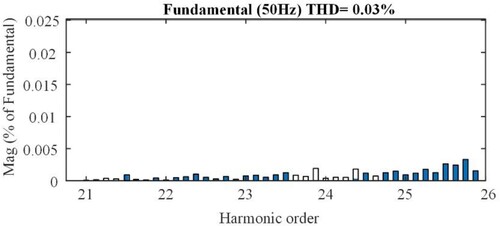
Figure 22. Suggested Real Power (P) comparison between several known optimization methods.
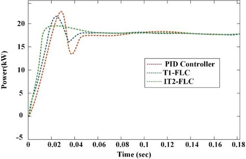
Figure 23. Suggested Reactive Power (Q) comparison between several existing optimization techniques.
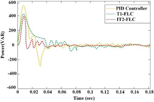
Table 2. Harmonic order comparison between before and After UPQC compensation.
Using a backup mechanism in the HSES-producing system, the output of the grid is modified under different environmental conditions. According to IEEE 519 standards, the PID controller with T1-FLC and IT2-FLC is configured to sustain grid power stability while lowering distortion to reduced proportions. The suggested Controllers attain better outcomes by retaining the system’s dependability and stability. By making the optimum signal for series and parallel active filters, the proposed controllers in the HSES linked grid integrated systems with the use of UPQC successfully reduce the power quality problems related to grid current, imbalanced load, dips, swelling, and disturbances.
6. Conclusion
The HSES Grid interfaced system’s improved power quality has become a real phenomenon that is being researched. But, when non-linear loads and fast switching features are applied, power quality issues arise on the load side. We must utilize specialized power electronic equipment essential in reducing comparable issues to solve concerns about power quality. A UPQC device controlled by an IT2-FLC-based controller is suggested in the paper. The correct gain value is mandatory to function the UPQC Control parameters formed using the T1-FLC and IT2-FLC techniques. The developed framework has previously undergone a number of assessments, including Harmonic distortion reduction, Mode II: PQ Improvement, and Mode I: PQ Improvement using RESP Power Injection (RESP > 0). In accumulation, we defined PQ problems such as voltage sags and swelling situations for voltage issues. The suggested method is put into practice in the MATLAB Simulation environment. The recommended technique delivers the greatest results compared to existing techniques like PID. In future, the proposed work will be implemented with hybrid optimization techniques and machine learning-based control techniques to improve the performance characteristics such as speed of the response and efficacy.
Disclosure statement
No potential conflict of interest was reported by the author(s).
References
- Zhu R, Andresen M, Langwasser M, et al. Smart transformer/large flexible transformer. CES Trans Electr Mach Syst. 2020;4:264–274.
- Naqvi SBQ, Kumar S, Singh B. Weak grid integration of a single-stage solar energy conversion system with power quality improvement features under varied operating conditions. IEEE Trans Ind Appl. 2021;57:1303–1313.
- Kumar A, Kumar P. Power quality improvement for grid-connected PV system based on distribution static compensator with fuzzy logic controller and UVT/ADALINE-based least mean square controller. J Mod Power Syst Clean Energy. 2021;9:1289–1299.
- Feng W, Sun K, Guan Y, et al. Active power quality improvement strategy for grid-connected microgrid based on hierarchical control. IEEE Trans Smart Grid. 2018;9:3486–3495.
- Chishti F, Murshid S, Singh B. Weak grid intertie WEGS with hybrid generalized integrator for power quality improvement. IEEE Trans Ind Electron. 2020;67:1113–1123.
- Jain V, Singh B. Power quality improvement in PV system tied to weak grid. IEEE Trans Ind Appl. 2021;57:1265–1273.
- Chishti F, Murshid S, Singh B. LMMN-Based adaptive control for power quality improvement of grid intertie wind–PV system. IEEE Trans Ind Inf. 2019;15:4900–4912.
- Yu J, Xu Y, Li Y, et al. An inductive hybrid UPQC for power quality management in premium-power-supply-required applications. IEEE Access. 2020;8:113342–113354.
- Sarita K, Kumar S, Vardhan ASS, et al. Power enhancement with grid stabilization of renewable energy-based generation system using UPQC-FLC-EVA technique. IEEE Access. 2020;8:207443–207464.
- Chen X, Ruan X, Yang D, et al. Injected grid current quality improvement for a voltage-controlled grid-connected inverter. IEEE Trans Power Electron. 2018;33:1247–1258.
- Verma A, Singh B. AFF-SOGI-DRC control of renewable energy based grid interactive charging station for EV with power quality improvement. IEEE Trans Ind Appl. 2021;57:588–597.
- Badoni M, Singh A, Pandey S, et al. Fractional-Order notch filter for grid-connected solar PV system with power quality improvement. IEEE Trans Ind Electron. 2022;69:429–439.
- Bonaldo JP, De Souza VA, Alonso AMDS, et al. Adaptive power factor regulation under asymmetrical and Non-sinusoidal grid condition with distributed energy resource. IEEE Access. 2021;9:140487–140503.
- Shukl P, Singh B. Recursive digital filter based control for power quality improvement of grid tied solar PV system. IEEE Trans Ind Appl. 2020;56:3412–3421.
- Hock RT, De Novaes YR, Batschauer AL. A voltage regulator for power quality improvement in Low-voltage distribution grids. IEEE Trans Power Electron. 2018;33:2050–2060.
- Shukl P, Singh B. Delta-Bar-Delta neural-network-based control approach for power quality improvement of solar-PV-interfaced distribution system. IEEE Trans Ind Inf. 2020;16:790–801.
- Chishti F, Murshid S, Singh B. Unbiased circular leakage centered adaptive filtering control for power quality improvement of wind-solar PV energy conversion system. IEEE Trans Sustain Energy. 2020;11:1347–1357.
- Riachy L, Alawieh H, Azzouz Y, et al. A novel contribution to control a wind turbine system for power quality improvement in electrical networks. IEEE Access. 2018;6:50659–50673.
- Benali A, Khiat M, Allaoui T, et al. Power quality improvement and Low voltage ride through capability in hybrid wind-PV farms grid-connected using dynamic voltage restorer. IEEE Access. 2018;6:68634–68648.
- Beniwal RK, Saini MK, Nayyar A, et al. A critical analysis of methodologies for detection and classification of power quality events in smart grid. IEEE Access. 2021;9:83507–83534.
- Moghassemi A, Padmanaban S, Ramachandaramurthy VK, et al. A novel solar photovoltaic Fed TransZSI-DVR for power quality improvement of grid-connected PV systems. IEEE Access. 2021;9:7263–7279.
- Shukl P, Singh B. Combined IIR and FIR filter for improved power quality of PV interfaced utility grid. IEEE Trans Ind Appl. 2021;57:774–783.
- Stonier AA, Murugesan S, Samikannu R, et al. Power quality improvement in solar fed cascaded multilevel inverter with output voltage regulation techniques. IEEE Access. 2020;8:178360–178371.
- Elmetwaly AH, Eldesouky AA, Sallam AA. An adaptive D-FACTS for power quality enhancement in an isolated microgrid. IEEE Access. 2020;8:57923–57942.
- Mayer MJ, Szilágyi A, Gróf G. Environmental and economic multi-objective optimization of a household level hybrid renewable energy system by genetic algorithm. Appl Energy. 2020;269:115058.
- Bajaj M, Singh AK, Alowaidi M, et al. Power quality assessment of distorted distribution networks incorporating renewable distributed generation systems based on the analytic hierarchy process. IEEE Access. 2020;8:145713–145737.
- Srikanth Goud B, Rao BL. An intelligent technique for optimal power quality enhancement (OPQE) in a HRES grid connected system: ESA technique. Int J Renewable Energy Res. 2020;10:318–328.
- Srikanth Goud B, Rao BL, Reddy CR. Essentials for grid integration of hybrid renewable energy systems: A brief review. Int J Renewable Energy Res. 2020;10:813–830.
Annexure
Table A1. Rule base for the proposed Membership Functions.
Table A2. Specifications of Solar, Wind, and Battery.