
 ?Mathematical formulae have been encoded as MathML and are displayed in this HTML version using MathJax in order to improve their display. Uncheck the box to turn MathJax off. This feature requires Javascript. Click on a formula to zoom.
Abstract
Nowadays, Photovoltaic (PV) system’s contribution to the power grid is increasing immensely. The PV system is linked with power grid through one or more inverters and a power conditioning unit to ensure smooth power delivery while also maintaining system voltage and frequency stability. However, due to grid load expansion, weak power grids have emerged as the dominant one today. As a result, the voltage and frequency of the grid got distorted. It may cause serious damage to the entire system in some cases. A single phase ZSI with the proposed Fractional order SMC technique is used to address these issues. The single phase ZSI consists of only two power switches and perpetuates the voltage transfer ratio like full bridge inverter. It also corroborates the sharing of power, regulatesactivepower,voltage, frequency, reactive powerand alleviates the harmonics in current. The input voltage of inverter is boostedby using theshoot through state and it also improvesthe reliability of inverter. The execution of the single phaseZSI withproposed FOSMCtechnique is assessed in MATLAB/Simulink to bear out the magnificent features of the proposed FOSMC in weak grid.
1. Introduction
Every day, we rely on electricity from the power grid. We have created a thriving, vibrant society that is entirely dependent on an operational electrical grid. The electrical grid affects every aspect of modern life. Based on short-circuit ratio (SCR), grid is classified as weak and stiff grid. When SCR is low, the grid is said to be weak and if it is high the grid said to be stiffed one [Citation1]. However, nowadays weak power grids are emerged as predominant one. The voltage at the connecting point will be very sensitive to any variation of the load in weak grids. A weak grid can cause distortion in voltage and frequency at the inverter terminals [Citation2]. Because of its massive consumption and exhaustion of fossil fuels, the perforation of renewable sources of energyin the electric field, especially solar energy, has reached the pinnacle [Citation3]. Solar energy is used in a variety of applications, from small buildings to large commercial buildings. The PV system is integrated to the grid via one or more inverters [Citation4]. As a result, the system become non reliable and instability.
When PV module directly linked to a load, maximum power operating pointbecomes infrequent. Because the output of a PV array is unregulated, it must be perfectly conditioned in order to affiliates with the grid [Citation5]. Boost converter with MPPT transfers maximum power from the PV module to the weak grid. Here, WOA is used in MPPT to get the most power out of a PV panel [Citation6–8]. WOA is inspired by humpback whale hunting behaviour and can applied to non-linear optimization problems too [Citation9,Citation10].
As PV inverters, traditional converter topologies such as VSIand CSI are commonly used [Citation11]. However, they are susceptible to electromagnetic interference (EMI) noise. The output of a VSI and CSI consists of two distinct voltage levels, but it suffers from higher switching losses [Citation12]. Traditional two-level inverters have a faster rate of change of voltage (dv/dt). The switching frequency is also high. They work best in low-voltage applications [Citation13,Citation14].
ZSI is a hybrid of VSI and CSI [Citation15]. Voltage is increased at the DC link using a novel technique known as shoot-through [Citation16]. Due to its unique circuit topology,without using DC-DC Converter Bridge it functions as a buck–boost inverter. However the operating nature of ZSI is achieved with a single stage power conversion [Citation17].
Here,single-phase ZSIis used that avail only two switches, low THD, low cost, and share the same ground for input and output. Here voltage stress across the switch is also minimum [Citation18–20]. The grid synchronization is essential to increase the stability of weak grid. Grid synchronization is a critical technique to connect the PV system to the grid. The ability of the synchronizing technique to provide instantaneous responses has collision on grid and inverter performance. Synchronization techniques found in recent publications [Citation21] include the Kalman filter [Citation22], the discrete FT method the zero-crossing detection method [Citation23,Citation24] and the phase-locked loop (PLL) methods. The phase-locked loop is used here for synchronization due to ease implementation, robustness, and low cost [Citation25].
Due to precision and robustness, the SMChas been utilized in power system field [Citation26]. It provide better performance in applications like voltage-sourced converters (VSC) and micro grids [Citation26,Citation27]. The actual controllers exclusively use integer-order either differentiators or integrators. But FOSMC use integerorder in fractions [Citation28]. By adopting proposed FOSMC control scheme, voltage distortion in weak grid can be reduced. The feasibility of the improved Z source inverter and its FOSMC control strategy is thoroughly examined and validated through simulation and experiments.
The key innovation of this research is described below:
A single phase Z source network is used because of versatile and generic network.
FOSMC controller is proposed which guarantees stability and the desired performance of the inverter in the presence of uncertainties in weak grids.
The WOA algorithm based MPPT to pursue the maximum amount of power from the PV panel.
The paper is organized as follows:
Section 1 furnishes recapitulationof the proposed work. Section 2 furnishes a detailed description of the proposed system in the form of a block diagram, as well as mathematical modelling of the various components used in the proposed system. Section 4 describes the proposed system control technique. Section 5 assesses the performance of the proposed model and displays the results. Section 6 concludes the paper with some concluding remarks.
2. Proposed methodology
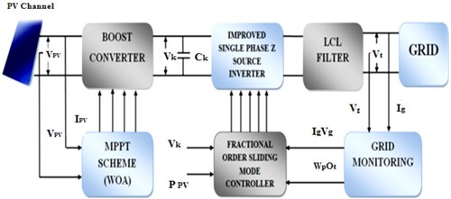
The PV strings in Figure are made up of small PV panels connected in series and parallel, a boost converter, a DC link capacitor, a single phase ZSI network, an LCL filter, and a single phase weak grid. The MPPT receives values of voltage and current from the PV panel. The most advantageous and efficient method is the WOA-based MPPT scheme, which is used to pursue the maximum amount of power of a PV panel. The output from MPPT is given to the boost converter in the form either as duty cycle or as voltage parameter. The boost converter integrates the solar panel to the load and also aids in maintaining the operating voltage at the MPP,by varying the duty cycle. The converter generates distorted dc voltage. The stabilization of the boosted DC voltage can be obtained by DC-link capacitor. The ZSI change the stabilizeddc voltage to ac for the case of weak grid. To reduce total harmonic distortion more, the single phase ZSI with less number of switches is utilized. The output of ZSI is connected to the LCL filters are utilizedto eliminate the current harmonics and to get desired performance. Grid monitoring is critical in the control system of a weak grid. It helps the system to stable by monitoring the distortions occur in weak grid and send signal to the controller about the distortion. It also allows the system to operate in normal mode with a power factor of one. Here for monitoring the grid PLL synchronization techniques is used because of its fast and accurate dynamics. The output from monitor is send to the proposed FOSMC controller. FOSMCis closed loop controllers provide smaller total harmonic distortion, eliminates system uncertainties. The proposed controller output send feedback to the inverter about the distortions occurs at the side of the weak grid.
Figure 1. Block Diagram for Single Phase ZSI Fed PV System in Weak Grids Using FOSMC.
2.1. Mathematical modelling of PV cell
The PV cellsare the basic unit and the integrant of a PV panel. When exposed to light, its electrical properties such as current, voltage, and resistance changePV cell electricity can be used for powering the load (Figure ).
Figure 2. Single diode model of a PV cell.
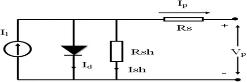
The VI characteristics equation of PV cell can be specified in mathematical description as follows:
Where, Il – currentfrom PV panel; Io-saturationcurrentof diode; Rs-series resistance of cell; A -Ideality factor of Diode; k -Boltzmann’s constant (1.38 × 10⁻²³ W/m2 K); q -magnitude charge of on an electron (1.6 × 10⁻¹⁹C); TC- working cell temperature; Isc-current occur at short circuit; KI-temperature coefficient of short circuit current; Tr- reference temperature; IRS- cells reveres saturation current; EG -semiconductor’sband-gap energy.
2.2. MPPT using WOA method
Under certain conditions, MPPT is a charge controller algorithm that is used to track the maximum available power from a PV module. Solar radiation, ambient temperature, and solar cell temperature affects the maximum power of PV module. Here WOA method of MPPT is used. The Whale Optimization Algorithm (WOA) was an innovative stochastic population algorithm. This algorithm was inspired by the social behaviour of humpback whales. Exploration and exploitation are the two stages of the search process. The first phase algorithm looks through the entire search space. In this paper, the second phase includes a detailed investigation of the optimal values of the PID controller KP, KI, and Kd. WOA mimics humpback whale hunting behaviour. Humpback whales can be seen foraging by blowing distinctive bubbles in a nine-shaped pattern. After several iterations, whales represent the search agents that will be used to find the best value for the controller gains.
2.3. Boost converter
The boost converter is a medium for transferring energy from a PV panel to ZSI. This is accomplished through the use of four components:a diode,an capacitor,an electronic switch andan inductor. The connection of a boost converterdepicts in Figure . It forms a switching cycle while processing energy absorption and injection. The average output voltage of the converter is controlled by the duration of the switching on and off time.
Figure 3. Boost converter.
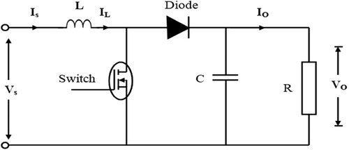
To avoid the inductor current ILobtaining zero and to get desiredvoltage ripple, the inductor and capacitance value should be determined. Let,
Where LM indicates the inductanceminimum value, CM represents thecapacitanceminimum value, R indicates the output resistance of the converter, and f indicates the switch's frequency, Vr represents the output voltage ripple factor.
Vr can be written as,
2.4. Single phase ZSI
Traditional VSI and CSI cannot provide features that a single phase ZSI can. It is straightforward, with only two switches. Furthermore, unlike conventional circuits, the ZSI circuits sharecommon groundfor input and output.
This inverter performs an unsymmetrical characteristic. Theinductors(La, Lb),capacitor (C), and input voltage source (Vi)make up the unsymmetrical Z-source network. The coupled inductors La and Lbcan act with any coupled factor. Where“d” is the S1's duty ratio, and the coupled inductance of La and Lbis mentioned as M. During a switching period, two states existand Figure depicts the ZSI equivalent circuit of switching period. Turned on the switch S1 and off the S2 switch in state 1. Dt denotes the time interval of state1 and t is the switching period of the state. In next state, turn on the switch S2 and off the S1.(1–D) tis mentioned as the time interval in this state (Figure ).
Figure 4. Single phase ZSI.

Figure 5. Equivalent circuits of switching period.
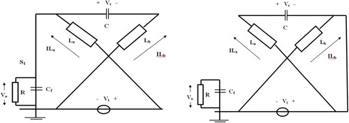
At state 1 we get,
In state 2,we can get,
At steady state,
2.5. Grid monitoring
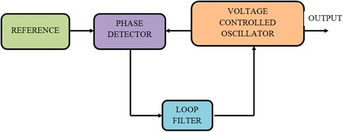
Grid monitoring is essential in a grid-connected PV system's control system. When fault occurs at voltage side on the weak grid, the PV system should instantly retaliate by grid fault operational mode switching rather than turning off. For fast and accurate dynamics, the most efficient technique, namely PLL synchronization techniques, should be used. Figure depicts the basic composition of a PLL systemandit consists of components like Phase Detector, Loop Filter and VCO. To improve the PLL filtering capability, the LF block is represented by a PI controller. An integrator is represented by the VCO block. The PD works similarly to a sinusoidal multiplier.
Figure 6. The basic composition of PLL.
3. Implementation of the proposed fractional order sliding modecontroller
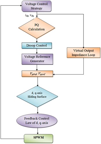
Under distorted load conditions, the FOSMC scheme maintains output voltage quality. Furthermore, compared to model predictive control and traditional SMC methods, the proposed control strategy employs fewer voltage sensors. The Lyapunov stability theorem demonstrates the controller's stability. Droop control is intended to ensure proper power sharing in a weak grid system. To obtain precise power-sharing with the load, the virtual output impedance loop is used. The modulation signals are obtained using control laws, and SPWMscheme is used to generate single phase ZSI’s gate signals (Figure ).
Figure 7. Schematic diagram of proposed FOSMC.
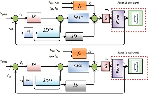
The proposed controller strategy regulates the ZSI external terminal voltage Vg's rotatory reference frame d and q-axis.
where, z = Vdc/2LCf, βd, βq – model disturbances
where,
βd, βq – model disturbances; fd and fq- nonlinear functions.
FOSMC is built around the sliding surface and the control lawparameters. Using the control law the system tracks the sliding surface. The d and q-axis control loops non-integer sliding mode surface is defined as follows:
where Ed and Eq represent voltage-tracking error and Dα−1 represents the fractional integral of (α− 1)thorder. Where,α, γ and λ are positive design choices parameters (α < 1 and γ < 1). The control laws on a sliding surface to slide the system to ensure fast and robust voltage-tracking error convergence are as follows:
where Kd and Kq are sliding gains.
Positive-defined Lyapunov candidate functions can be used to justify the proposed controller:
The time derivative of with respect to time we get (Figure ):
Figure 8. Flowchart for the proposed fractional-order sliding mode control.
5. Simulation results and discussion
The simulink model for the proposed system was created in MATLAB/SIMULINK and runs on a Windows 10 operating system with an i7 processor, 1TB hard disk, and 8GB RAM.
In weak grid system, the FOSMC is applied to a single phase ZSI circuit where the PV module provides power to the load. The cell parameters for a Sun Power SPR-305 WHT mono-crystalline silicon module are used as follows:
The cell parameters are used are tabulated in Table . Figures and represents the solar PV and IV characteristics obtained at the cell temperature 25°c and irradiance of 1000 wb/m2. Solar radiation, ambient temperature, and the temperature of the solar cellaffect the maximum power. At 25°C cell temperature, the PV module prompts power with a maximum voltage of around 16 V. At hotty day, the voltage will drop to 15 V and on cold day voltage rise to 18 V. The voltage, current and power of PV cell using MPPT is shown in Figure .
Figure 9. P-V Characteristic of PV array.
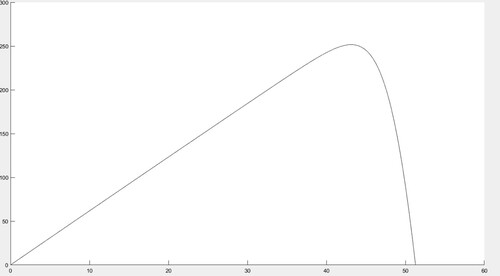
Figure 10. I-V Characteristic of PV array.
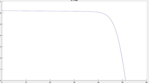
Figure 11. Voltage, current and power of PV system after MPPT.
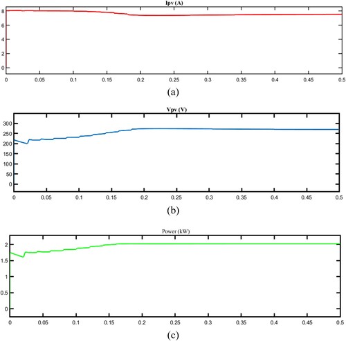
Table 1. Cell parameters of PV module.
The boost converter, which is linked between the solar panel and the load, is used to vary the duty cycle to keep the operating voltage at the maximum power point. Table lists the Boost converter's parameters (Figure ).
Figure 12. Output of boost converter voltage.
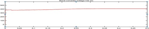
Table 2. Boost converter parameters.
CSI, VSIandZSIare commonly used as PV inverters in grid connected PV system. While comparing thesePV inverters, Z Source inverter is preferred more than VSI and CSI in most of the applications due to advantages like buck- boost mode and low THD (Figure and Table ).
Figure 13. Voltage and capacitor current of ZSI.
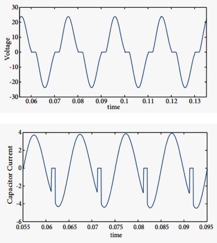
Table 3. Comparison of PV inverters.
MATLAB/Simulink is used to signify the performance of the proposed FOSMC for ZSI. The proposed technique’s results are compared to the conventional PID and PR controllers. Tables and show the inverter parameters as well as the control parameters. The proposed controller's effectiveness is assessed by comparing THD, steady-state error, settling time, and robustness.
Table 4. Z Source InverterParameters for FOSMC.
Table 5. Parameters used for comparing FOSMC, PID, PR.
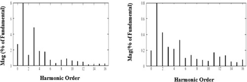
The Figure depicts the output waveform of voltage and current of the proposed FOSMC-based ZSI. Both waveforms are stable and sinusoidal, as can be seen. The reference sinusoidal signal is tracked by the proposed controller efficiently to indicate the control framework's robustness and precision. Figure shows the Voltage at d and q axis. The Total Harmonic Distortion of FOSMC's output voltage is 0.39%. Figures and shows the THD Spectrum as well as the waveforms of the PID, PR controller's output voltage and current. The THD of the PID and PR output voltages is 0.87 and 1.76%, respectively Figure .
Figure 14. Voltage and Current of FOSMC based ZSI.
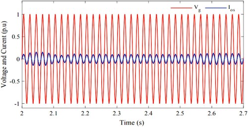
Figure 15. Voltage at d and q axis.
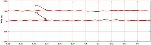
Figure 16. THD spectrum of FOSMC based ZSI.
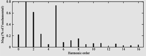
Figure 17. Voltage and Current of PID,PR Controller based ZSI.
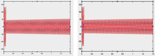
Figure 18. THD spectrum of PID, PR Controller based ZSI.
Based on simulation results, the proposed FOSMC performance is more robust and precise than other controllers. The FOSMC is unaffected by external disturbances or system uncertainties. It has very good voltage regulation performance and exceptional THD compensation. As a result, the FOSMC-based ZSI is best suited for poor grid performance. Table compares the THD, steady-state error, robustness, controller complexity, response time, and tracking accuracy of the proposed FOSMC, PID, and PR controllers. The FOSMC adds a degree of freedom that improves robustness and accuracy.
Table 6. Performance comparison of FOSMC, PR, PID controllers.
The proposed method is worthy to analysis the real time faults occur in power system. These faults or short circuits are caused primarily by overvoltage caused by switching, overvoltage caused by lightning strikes, bridging of conductors by birds, and sudden interruption of heavy load. Although these over voltages are not strong enough to damage system insulation, they should be avoided to ensure the smooth operation of the electrical power system. Overvoltage stresses on the power system are typically transient in nature. Grid monitoring helps the system to stable by monitoring the voltage distortions occur in powersystem and send signal to the controller about the distortion. FOSMCeliminates system uncertainties with smaller total harmonic distortion and send feedback to the inverter about the distortions.
6. Conclusion
In this paper, the Fractional order SMC technique was proposed for single phase ZSI fed PV system in weak grid. The proposed fractional-order SMC's performance was evaluated by comparing it to PID and PR controllers. This control strategy can effectively eliminate the output voltage THD and improves robustness and accuracy. It maintains excellent voltage regulation, as measured by steady-state error. External disturbances and system parametric uncertainties had no effect on the FOSMC. The Lyapunov stability theory was used to signify the stability of the FOSMC control strategy in a weak grid. MATLAB can be used to validate the simulation results. The system will give the FOSMC system greater control strategy in a weak grid because of its excellent voltage regulation contribution. Future research should take into account the accuracy and resilience of the reactive power management solution as well as the FOSMC.
Disclosure statement
No potential conflict of interest was reported by the author(s).
References
- Amin M, Stringer J. The electric power grid: today and tomorrow. MRS Bull. 2008;33(4):399–407. doi:10.1557/mrs2008.80
- Adib A, Mirafzal B, Wang X, et al. On stability of voltage source inverters in weak grids. IEEE Access. Jan 2018;6:4427–4439. doi:10.1109/ACCESS.2017.2788818
- Kute UT, Ratnaparkhi PS. Literature survey on maximum power point tracking (mppt) technique for photovoltaic (pv) system. Int J Adv Res Eng Appli Sci. December 2013;2(12):13–29.
- Koutroulis E, Kalaitzakis K, Voulgaris NC. Development of a microcontroller based photovoltaic maximum power point tracking system. IEEE Trans Power Electron. 2001;16(1):46–54. doi:10.1109/63.903988
- Banu IV, Istrate M. Modeling of maximum power point tracking algorithm for photovoltaic systems. Iasi: Gheorghe Asachi, Technical University of Iasi.
- Yadav APK, Thirumaliah S, Haritha G, Scholar PG. Comparison of MPPT algorithms for DC-DC converters based PV systems. Int J Adv Res Electr Electron Instrum Eng. 2012;1(1):18–23.
- Mohan N, Undeland TM, Robbins WP. Power electronics: converters, applications, and design. Delhi: John Wiley & Sons; 2003.
- Hasaneen BM, Mohammed AAE. Design and simulation of DC/DC boost converter. 2008 12th International Middle-East Power System Conference. IEEE; 2008. p. 335–340.
- Mirjalili S, Lewis A. The whale optimization algorithm. Adv Engg Softw. 2016;95:51–67. doi:10.1016/j.advengsoft.2016.01.008
- Reisi AR, Moradi MH, Jamasb S. Classification and comparison of maximum power point tracking techniques for photovoltaic system: a review. Renewable Sustainable Energy Rev. 2013;19:433–443. doi:10.1016/j.rser.2012.11.052
- Mohan N, Robbin WP, Undeland T. Power electronics: converters, applications, and design. 2nd ed New York: Wiley; 1995.
- Trzynadlowski AM. Introduction to modern power electronics. New York: Wiley; 1998.
- Lee BK, Ehsami ML. A simplified functional simulation model for three-phase voltage-source inverter using switching function concept. IEEE Trans Ind Electron. April 2001;48(2):309–321.
- Klumpner C. A new single-stage current source inverter for photovoltaic and fuel cell applications using reverse blocking IGBTs. Proc IEEE Power Electron Spec Conf. 2007: 1683–1689.
- Peng FZ. Z-source inverter. IEEE Trans Ind Appl. Mar/Apr 2003;39(2):504–510. doi:10.1109/TIA.2003.808920
- Xu P, Zhang X, Zhang C-w, et al. Study of Z-source inverter for grid-connected PV systems. 37th IEEE power electronics specialists conference; 2006. doi:10.1109/pesc.2006.1712266
- Huang Y, Shen M, Peng FZ, et al. A Z-source inverter for residential PV systems. IEEE Trans Power Electron. Nov 2006;21(6):1776–1782. doi:10.1109/TPEL.2006.882913
- Shen MS, Wang J, Joseph A, et al. Constant boost control of the Z-source inverter to minimize current ripple and voltage stress. IEEE Trans Ind Appl May/Jun. 2006;42(3):770–777. doi:10.1109/TIA.2006.872927
- Loh PC, Vilathgamuwa DM, Lai YS, et al. Pulsewidth modulation of Z-source inverters. IEEE Trans Power Electron Nov. 2005;20(6):1346–1355.
- Shen M, Peng FZ.. Control of the Z-source inverter for fuel cell-battery hybrid vehicles to eliminate undesirable operation modesConference Record of the 2006 IEEE Industry Applications Conference Forty-First IAS Annual Meeting, vol. 4. IEEE; Oct 2006. p. 1667–1673.
- McGrath BP, Holmes DG, Galloway JJH. Power converter line synchronization using a discrete Fourier transform (DFT) based on a variable sample rate. IEEE Trans Power Electron. 2005;20:877–884. doi:10.1109/TPEL.2005.850944
- Reza MS, Ciobotaru M, Agelidis VG. Instantaneous power quality analysis using frequency adaptive Kalman filter technique. In Proceedings of the 7th International power electronics and motion control conference (IPEMC 2012); Harbin, People’s Republic of China; 2–5 Jun 2012. p. 81–87.
- Weidenbrug R, Dawson FP, Bonert R. New synchronization method for thyristor power converters to weak AC-systems. IEEE Trans Ind Electron. 1993;40:505–511. doi:10.1109/41.238019
- Vainio O, Ovaska SJ. Noise reduction in zero crossing detection by predictive digital filtering. IEEE Trans Ind Electron. 1995;42:58–62. doi:10.1109/41.345846
- Filho RMS, Seixas PF, Cortizo PC, et al. Comparison of three single-phase PLL algorithms for UPS applications. IEEE Trans Ind Electron. 2008;55:2923–2932. doi:10.1109/TIE.2008.924205
- Chen Z, Luo A, Wang H, et al. Adaptive sliding-mode voltage control for inverter operating in islanded mode in microgrid. Int J Electr Power Energy Syst. March 2015;66:133–143. doi:10.1016/j.ijepes.2014.10.054
- Su X, Han M, Guerrero JM, et al. Microgrid stability controller based on adaptive robust total SMC. Energies. Mar 2015;8(3):1784–1801. doi:10.3390/en8031784
- Zhang BT, Pi YG, Luo Y. Fractional order sliding-mode control based on parameters auto-tuning for velocity control of permanent magnet synchronous motor. ISA Trans. 2012;51(5):649–656. doi:10.1016/j.isatra.2012.04.006