
 ?Mathematical formulae have been encoded as MathML and are displayed in this HTML version using MathJax in order to improve their display. Uncheck the box to turn MathJax off. This feature requires Javascript. Click on a formula to zoom.
Abstract
Smart renewable energy harvesting has been implemented from hybrid sources such as solar and wind. The wireless sensor node is created for monitoring surface water. In the intelligent building, electrical energy is harvested from the hybrid source of solar and wind energy. The source energy was selected for the harvesting process by using a fuzzy controller. In this proposed method, piezo-electric reverse electro-wetting on di-electric energy harvesting is proposed where constant DC voltage is generated by a rectifier. A DC-DC converter is designed to power up the remote read-out sensor. The produced charge is transformed by a charge amplifier with the proportion of output voltage that is delivered to the wireless receiver. The harvested DC voltage varies with the temperature and external environmental effect. In our work, we obtained 6 × 10⁻³ W/m2 of voltage and this harvested energy is monitored using the Internet of Things (IoT) by the proposed EHOR (Energy Harvested Optimized Routing) algorithm.
1. Introduction
This paper describes the implementation of energy harvesting from hybrid sources such as solar energy and wind energy. The harvested energy is monitored by the Internet of Things in wireless sensor networks. In recent years, the WSN and micro-electronics play a vital role in the development of energy harvesting [Citation1]. IoT and wireless sensors are widely used as smart equipment that can be placed in remote areas and difficult to charge batteries [Citation2]. One of the examples is controlling electrical devices in smart buildings. Major progress in limited integrated circuit design batteries’ activation energy must be enhanced as the energy requirements for the proposed protocols are challenging to meet [Citation3,Citation4]. As a result, renewable energy-collecting approaches must be developed to support these self-powered devices. The harvesting energy must be a self-powered system; nevertheless required as a sustainable and cost-effective replacement to batteries, it also helps to minimize greenhouse emissions and combat climate changes [Citation5]. Accordingly, it is necessary to enhance energy harvesting to strengthen the self-power system. The self-powered systems generally have three parts: energy source, energy harvesting and load to store the energy. The energy source can be solar, vibration, wind, water, etc. [Citation6]. The harvesting mechanism is that converting ambient (mechanical) energy into electric energy [Citation7,Citation8]. The load is a sink that stores the electric energy.
The energy harvesting part is made up of many elements including a centre non-active layer (core) and a core layer connected to either side by a piezoelectric element active layer. A stiff, stretchy polymer is typically used to encircle the core, increasing the lateral deformation that subsequent layers flow around. Although any robust piezoelectric or electro-stricture substance may be used in the producing layers, this study will examine how certain possibilities are superior to others. The purpose is to increase the pressure in the layered structure as much as possible [Citation9]. The electrical power P generated by an energy harvesting [Citation10] swaying in a water flow is measured by Equation (1).
(1)
(1) where
is the efficiency of hydro-dynamic that depends on the oscillation of the water flow;
is the efficiency of piezo-electric component/reverse electro wetting on di-electric energy harvesting that makes electrical energy from the hybrid energy;
is the efficiency/productivity of the electricity generated which denotes electric loss function in the resonant circuit i.e. output power of the circuit used. A represents the energy harvesting's circumference. Water's density and velocity are measured as
and V, respectively. Hybrid energy harvesting systems typically involve the combination of multiple energy sources, such as solar, wind, vibration, or thermoelectric, to enhance overall energy harvesting performance. Dynamic control methods are applied to manage and balance the energy harvested from different sources, adapting to varying environmental conditions and load demands [Citation8]. Although many energy harvesters implemented and have been used commercially; it is quite essential to build intelligent /smart buildings by harvesting energy from the water flow economically. As global energy demands escalate, there is a critical need for sustainable and efficient energy harvesting solutions. This research project aims to develop a Hybrid Energy Harvesting System that employs reverse di-electric on a piezoelectric generator, coupled with thermocouple integration. The primary challenge is to optimize energy extraction from solar and wind sources to power wireless sensor nodes for surface water monitoring in intelligent buildings. The challenges include (i) Achieving optimal efficiency in energy harvesting systems across diverse environmental conditions is a significant challenge. (ii) Integrating a fuzzy controller for dynamic source selection introduces complexities in optimizing energy harvesting in a hybrid model. (iii) Designing a monitoring system within wireless sensor networks (WSN) that efficiently captures and transmits harvested energy data in real time poses a challenge. These challenges underscore the need for innovative solutions to enhance overall energy harvesting efficiency and enable reliable and sustained power generation for surface water monitoring in intelligent buildings.
2. Literature review
To construct an IoT-based WSN in energy harvesting using solar the model is constructed with a bluffy body and flexible membrane [Citation11]. It is necessary to measure the frequency of the water flow to generate the energy. The energy harvester can generate energy up to 720 mW in the opened tap with a flow rate of 20 L per minute. The output power used in this scenario is 2 mW [Citation12]. Behind the bluffy body, the vortex scavenges energy and converts it to electrical power [Citation13]. The experiment that collects energy from the flow tank can generate 1 mW of power using a nominal water flow [Citation14]. This is achieved by a mass spring system and two piezo-electric lever devices were designed and harvest energy at deep ocean wave vibrations. The energy is harvested from the average flow water channel with the velocity set to 0.1 m/s using a piezo-electric device [Citation15]. In smart buildings, the energy can be harvested using load shifting and load reduction with adaptive systems [Citation16]. Energy building management systems and building automated control can carry out some smart building operations, such as lighting and HVAC [Citation17]. Automation controls need to be empowered with trustworthy, secure and economical features, which encourage IoT integration. Controlling elements and sensors in the Routing algorithm are in charge of the intelligent building [Citation18]. As the Internet of Things, machine learning, big data, virtualization, as well as automation techniques advance, smart technologies are growing closer to becoming sustainable structures [Citation19]. In essence, networking, modulation schemes, management services and components, operational extracting information, storage systems and detectors manage all of the essential machinery inside of an energy-efficient building. Sensors are critical components in the adaptive and management to construct smart management in buildings. Occupancy sensors let consider that assist in the regulation of building systems to attain 15 per cen to 40 per cent of PE overall energy can be saved [Citation20]. Sensors for detecting parameters, such as temperature, moisture, Carbon dioxide, organic compounds, habitation, vicinity, altitude, movement, pollution, vibrations and light levels, are accessible on the market. A suitable position, implementation and configuration of these devices ensure that factors are properly monitored [Citation21]. The flow of water throughout the integrated platform is utilized to generate electricity. The piezo-electric generator is used to capture the energy from water flow, and the sensors that serve as the communication subsystem are controlled by the MSP 430 controller and accompanying electronics. Triboelectric Nanogenerators (TENGs) are a promising and innovative method for hybrid energy harvesting, showcasing their versatility and efficiency in converting mechanical energy into electrical power. TENGs operate on the triboelectric effect and electrostatic induction, utilizing the contact and separation of different materials to generate a charge imbalance and induce electric current flow. This unique mechanism enables TENGs to harness energy from various sources, including mechanical vibrations, human motion, wind and water flow [Citation22,Citation23].
3. Piezo-electric generator
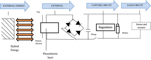
Earlier the energy was harvested from wind and solar based on the piezo-electric elements. Piezo-electric materials are known for their ability to convert mechanical forces into electrical charges and vice versa – a phenomenon termed the piezoelectric effect. This unique electromechanical characteristic positions these materials as essential components in various applications, including sensors, actuators, transducers and energy-harvesting devices. Among the well-known piezoelectric materials are quartz, lead zirconate titanate (PZT), barium titanate, ceramics and polymers, each possessing unique attributes that influence material selection based on specific application requirements. Essential electromechanical properties integral to understanding and utilizing piezoelectric behaviour include the Piezoelectric Coefficient (d), representing the connection between mechanical stress and electric charge; the Piezoelectric Modulus (e), indicating the ratio of an induced electric field to applied mechanical stress; the Dielectric Constant (ϵ), affecting the material's capacity to store electrical energy; the Elastic Modulus (Y), reflecting material stiffness under mechanical stress and the Curie Temperature (Tc), marking the temperature at which ferroelectric materials undergo a phase transition, losing their piezoelectric properties. This in-depth comprehension is crucial for researchers and engineers designing and optimizing devices that integrate piezoelectric materials, ensuring tailored choices to address specific electromechanical requirements across diverse applications. The hybrid energy is the input to the piezo-electric energy harvester circuit. The piezo-electric layer lies in between the electrodes, as shown in Figure . The piezo-electric beam is packed with the FR4 with a thickness of 0.8 mm that connects the electric circuit, as shown in Figure .
Figure 1. Piezo-electric linear harvester setup.
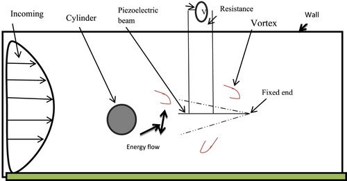
Figure 2. Piezo-electric circuit.
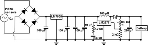
The model was built for energy harvesting in a linear model with a resonant frequency of about 3 Hz. Piezo-electric sensors measure the piezo-electric effect generated from the hybrid source such as force, acceleration, pressure and temperature. The piezo-electric sensors are connected linearly and all are covered with glass at the edges to avoid damage during the harvesting of energy. The RMS output was 1 V for each sensor with 100 mA current. Since the piezo-electric is in AC form, to keep this circuit rechargeable it needs to be converted to DC. The current and the AC voltage are fed into a full wave rectifier circuit that has four diodes and a capacitor, as shown in Figure . The output obtained from the rectifier is 4.5 V; due to the replication, the LM7805 is added to the unit to maintain an output of 3.4 V.
Figure 3. Overall circuit diagram piezo-electric generator.
4. Reverse di-electric on a piezo-electric generator with thermo-couple
For several decades, maintaining the intelligent/smart building energy harvesting system has been a critical bottleneck. To convert the hybrid energy source into electric energy, this reverse di-electric electro phenomenon is proposed. This is more suitable for portable applications. Electro-wetting on di-electric is the classical approach that produces energy when the interaction of arrays of generated energy with a novel multi-layer phenomenon. The piezo-electric generator and the di-electric energy generator are used with low vibration/poor environment. To produce energy efficiently in mobile applications and to generate energy with greater frequency reverse di-electric electro-wetting is implemented, as shown in Figure .
Figure 4. Reverse di electric on piezo-electric generator.
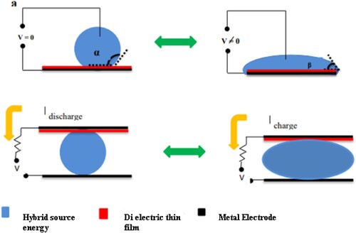
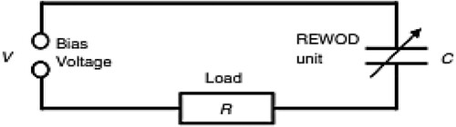
This approach is straight-forward where the source energy and electrode are connected to the external circuit which provides the constant bias voltage. The hybrid mechanical energy applied by the solar and wind is employed to the circuit in such a way that overlapping with the di-electric film electrode is reduced. The elevation of the energy level barrier is lowered. This thermocouple is used to connect the two different wires that carry hybrid energy where one junction is for temperature and the other junction is for emf. This thermocouple wire is connected to the circuit with an energy harvesting circuit. The produced electric charge again travels back to the electric circuit, as shown in Figure , connecting the hybrid source and the electrode. The electrical current produced can power the external load. This reverse di-electric energy is generated in a variety of different geometries as in-plane shear, out-of-plane intensity and in-channel direction. The hybrid source travels in and out of alignment with the electrified thin-film-di-electric-coated electrodes as it moves in and out of alignment with them. Changes in the quantity of electrical charge at the electrodes cause a flow of electrical current.
Figure 5. Reverse circuit.
The provided text describes a conceptual framework for a reverse dielectric electro-wetting energy harvesting system. While it provides a detailed explanation of the system's operation and components, it doesn't explicitly include mathematical equations. However, I can help you formulate some mathematical representations based on the described concepts. These equations are illustrative refinements based on specific system parameters and characteristics. Let be the harvested power and
be the external voltage generated by the system. The relationship between harvested power and external voltage can be expressed as
(2)
(2) where
is the external current produced.
The reverse dielectric electro-wetting phenomenon involves reducing the overlap with the dielectric film electrode to lower the energy level barrier. This can be qualitatively represented as
(3)
(3) where
represents the energy level barrier. The thermocouple is used to connect two different wires carrying hybrid energy, where one junction is for temperature T and the other for electromotive force (emf). The “S” Seebeck effect in a thermocouple can be represented as
(4)
(4) where S is the Seebeck coefficient and ΔT is the temperature difference. The flow of electrical current
through the circuit can be represented using Ohm's Law:
(5)
(5) where
is the external resistance.
This approach offers advantages for mobile applications by providing efficient energy production through reverse di-electric electro wetting on a piezoelectric generator, enabling sustainable power for mobile devices. Additionally, the method allows for flexibility in adapting to varying frequencies, enhancing versatility in mobile energy solutions. The dielectric film in this energy generation method is crucial as it enhances lateral deformation, reducing overlap between the hybrid mechanical energy source and the electrode. This results in increased energy efficiency and improved performance of the piezoelectric generator. The method allows for a wide range of mechanical pressure and lateral displacement by utilizing reverse di-electric electro wetting, enabling efficient energy harvesting across varying conditions and sources. The main purpose of implementing the reverse-di-electric electro phenomenon is to enhance energy harvesting efficiency in the smart building system by reducing the overlap between the hybrid mechanical energy source and the electrode, thereby optimizing energy extraction for sustainable power generation.
5. Monitoring system based on IoT
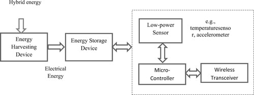
The monitoring system based on IoT, depicted in Figure , represents a pivotal component in the hybrid energy harvesting setup. In this illustration, wireless sensor networks (WSNs) play a central role as they are harnessed by the Internet of Things (IoT) to oversee the collected energy. The stored energy resides in a system equipped with batteries, ensuring a reliable repository for the harvested power. To track the movement and energy levels of the system, a low-power sensor is intricately connected to a microcontroller and an energy storage device. The microcontroller, often considered the brain of the IoT system, assumes a critical role in governing the efficient flow of energy within the entire setup. Through this interconnected network, the IoT system ensures that the collected energy is effectively managed, providing a dynamic and responsive control mechanism that enhances the overall performance of the hybrid energy harvesting system.
Figure 6. IoT monitoring system.
Each sensor sends the data it has collected to the microcontroller. Data are subsequently transmitted to the WSN. Through an area network (wi-fi) connection, the information is sent to an online database called Firebase. A web application is used to read and show the data delivered to Firebase. The information is presented in a table for a historical perspective and is shown in several graphs for a real-time perspective. A cloud storage database powered by Google is called Firebase Real-Time Database. While maintaining real-time synchronization with the client, it saves data in JSON files [Citation24]. If indeed the device has a reliable Connection, it will respond immediately to any updates. Impact on the choices and modifications provided by the user, it stores the incoming information in a tree with node structure. Through a backend online storage system called Firebase Real-time Database, the front-end websites and physical reverse di electrical circuit are connected in network nodes in this work. The repository will hold real-time sensor information, and a JavaScript function will retrieve the information of timestamps from the database.
6. Routing packets in WSN
The energy harvesting-wireless sensor networks would not stop functioning until there was a hardware breakdown when the power dissipation was less than the power gathered during a particular working cycle. As a result, routing optimization using EH-WSNs currently aims to increase the amount of load that the connectivity can sustain autonomously under environmental circumstances. The pseudocode for Energy harvesting Opportunistic Routing protocol is shown in Tables and . For each charging cycle the data packet “DP” is received which is calculated as
(6)
(6) where
is the energy harvested depending on traffic and rate of energy harvesting and
represents the time taken at sending and receiving state, respectively.
can be calculated as
(7)
(7)
represents the maximum receiving state time. The total energy harvesting can be calculated as
(8)
(8) where
represents the receive state maximized energy,
indicates the energy needed to send a data packet,
represents energy that changing from the receiving stage to the broadcast stage is necessary. The average charging time is calculated as
(9)
(9) In this study, a hop energy-harvesting WSN with a single docking station and energy-harvesting member nodes acting as sink nodes with an endless supply of power and network connectivity are considered. The node transmission power is programmable, thus nodes might alter it depending on the distance. Sensor node data packets are later sent to the docking node. Additionally, each sensor node could serve as a router for other nodes.
Table 1. Proposed EHOR pseudo-code.
Table 2. Procedure to receive data packet, transmit data packet and end receive data packet.
The harvested energy is forwarded as data packets in the network have three functions such as receiving data packets, transmitting data packets and end receiving. The nodes in the network receive the data packets from the buffer while forwarding. The docking node in the network acts as a base node that collects all data packets. The transmitter node transmits the data packets to the base node. If there are no data packets to transmit the data packets then receive data packet function will end the data packet transmission. The state of the network remains charging if no data packets are found in the network through the buffer.
The variability in harvested energy poses challenges in maintaining A consistent power supply for applications. Fluctuations can affect the reliability of wireless sensor networks and connected devices. The proposed method addresses these challenges through the integration of a fuzzy controller for dynamic source selection, optimizing energy harvesting from solar and wind and employing an EHOR algorithm for efficient routing in the wireless sensor network. These strategies enhance adaptability to varying energy inputs, ensuring stable and uninterrupted system performance.
7. Experimental results and discussion
The result of this work is analysed into two subsections Such as energy harvesting and Routing in wireless sensor networks.
7.1. Energy harvesting
Energy harvested per cycle in reverse di-electro wetting is represented as E. The result E is calculated as
(10)
(10) The power P in reverse di-electro wetting is calculated as
(11)
(11)
is calculated as
that have maximum capacity of the capacitor. R is the load impedance; h is the thickness of the di-electric film with k constant; A is the overlap between droplets and electrode and
is the vacuum permittivity.
is calculated as
, where T is the period of one cycle in reverse di-electro wetting. This proposed technique is fundamentally simple conceptually. The energy-harvesting design is shown in Figure and the energy generated is calculated using Equation (10) and Equation (11).
Figure 7. Hybrid energy harvesting design.
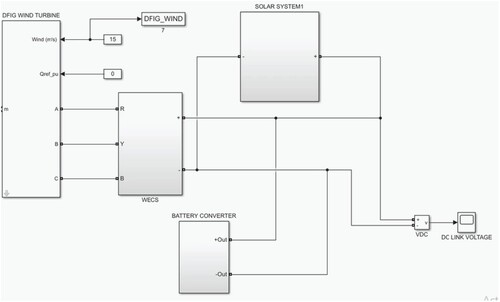
The external electrical circuit that supplies a continuous bias voltage seen between di electric plate as well as the rectifiers is linked to both the electrodes and indeed the hybrid source. The hybrid source is moved using externally applied actuation to reduce the overlapping between it and the electrode covered in a dielectric layer. This leads to a reduction in the overall charge which can still be sustained at the channel of harvesting energy. The additional electrical charge is then returned through all the connection that joins the source as well as an electrode, creating a current that may be used to power tensile stresses. As seen in Figure , the voltage generated using wind energy is about 6 V where the energy and power regularly alter per the passage of the energy in the channel. In this process, hybrid source actuation using a fuzzy controller influences the generation of energy. Figure represents the efficiency and voltage generated using solar energy. The source of energy is changed by the battery switcher with a fuzzy logic controller.
7.2. Routing in WSN
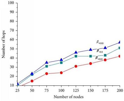
The good put-to-source sending rate ratio is known as the data delivery ratio. For each packet sent by the source node, this measure calculates the likelihood that it will reach its destination at the sink. Similar to this, having 0 improves the delivery rate. We also take hop count and efficiency into account. Efficiency is the proportion of throughput that obtains goodput. The probability that a packet will be a distinctive package once it is accepted by the receiver is another way to describe it. A hop count metric describes the typical number of data packets needed for a transmission to reach the sink. To use the energy harvested from hops as efficiently as possible, high effectiveness and reduced hop count are preferred, as depicted in Figure .
Table depicts the comparison of existing and proposed methods in recent years. The energy sources such as wind, solar, thermal and ambient energy are used to harvest the energy in different environments and with different harvester techniques. Overall, the table encompasses a diverse range of energy sources, harvester technologies and harvested power densities. The proposed method stands out for its unique approach and the potential for high efficiency in energy harvesting. By comparison, our proposed method obtains the highest energy harvesting power as 6 × 10⁻³ W/m2. The incorporation of a thermocouple to connect two different wires carrying hybrid energy, with one junction for temperature and the other for electromotive force (emf), demonstrates a thoughtful integration of technologies. This design allows for the effective coupling of temperature differentials with the electromotive force, potentially improving energy conversion efficiency. The description of the produced electric charge travelling back to the electric circuit implies a form of charge recycling. This feature can contribute to overall energy efficiency, allowing the system to maximize the utilization of generated electric charges. Including constant bias voltage, optimized energy application, thermocouple utilization, versatility in energy generation geometries, alignment dynamics and electric charge recycling collectively suggest that the described Reverse Dielectric on a piezo-electric generator approach may offer advantages in terms of efficiency, adaptability and responsiveness compared to existing methods.
Table 3. Comparison of existing and proposed models.
The energy harvested per cycle in reverse di-electric electro-wetting is represented by the parameter E. The calculations for E and power P are based on specific formulas involving variables such as voltage (V), capacitance (C0), load impedance (R), thickness of the dielectric film (h) and vacuum permittivity (ε0). The proposed hybrid energy harvesting system involves a di-electric plate with externally applied actuation to reduce the overlap between it and the electrode. This method enhances energy harvesting efficiency, and the results are presented through figures, including a hybrid energy harvesting design (Figure ), voltage generated from solar energy (Figure ) and voltage generated from wind energy (Figure ). The hybrid source actuation, guided by a fuzzy controller, plays a key role in influencing energy generation. The harvested DC voltage fluctuates with temperature due to temperature-dependent characteristics of electronic components and materials, impacting the efficiency of energy conversion. External environmental factors, such as sunlight intensity and wind speed, influence solar panels and wind generators, leading to variations in harvested voltage. Thermoelectric effects and changes in piezoelectric material properties contribute to voltage variability in response to temperature shifts. Thermal expansion and contraction of materials within the system can alter mechanical properties, affecting energy-harvesting efficiency. To address these variations, designers implement temperature compensation techniques and choose components with stable characteristics across diverse environmental conditions.
Figure 8. Voltage generated – solar energy.
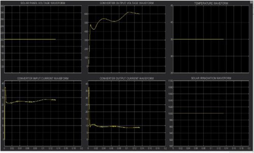
Figure 9. Voltage generated – wind energy.

Efficiency and hop count in the wireless sensor network (WSN) are crucial factors considered in the research. Figure illustrates the relationship between efficiency and hop count, emphasizing the importance of high efficiency and a reduced hop count for optimal energy utilization. The comparison of the proposed model with existing methods is presented in Table , showcasing a unique hybrid source approach using reverse di-electric on a piezo-electric generator. The proposed method outperforms existing techniques, achieving the highest energy harvesting power of 6 × 10∧(−3) Wm². The incorporation of a thermocouple for hybrid energy connection demonstrates a thoughtful integration of technologies, offering potential advantages in terms of efficiency, adaptability and responsiveness compared to traditional methods. The research work contributes to the field of energy harvesting by introducing a novel hybrid approach and demonstrating its efficiency through detailed analyses and comparisons with existing models.
Figure 10. Efficiency and hop count.
8. Conclusion
Increasing energy requirements will necessitate improved energy absorption peak procedures, which will be needed by energy harvesting techniques applied for Internet of Things sensors and equipment. Forthcoming energy harvesting procedures are being thought upon by several investors. In this paper, electrical energy is created when arrays of hybrid source energy contact with novel, dielectric film that are only a few nanometers thick. This method produces high output power up to 6 × 10⁻³ W/m2 and can effectively obtain output from a wide variety of power flows, from several volts to ten volts. A wide range of mechanical pressure and lateral displacement can also be applied directly. This method is suitable for elevated energy harvesting from many atmospheric sources of energy due to these benefits. The harvested energy is monitored by the Internet of Things. The harvested energy is transmitted as data packets in the network by the proposed EHOR approach. The data packets are transmitted with improved efficiency and good throughput. There are also challenges like managing the transmit power to save energy efficiently and to have regulation of sensor nodes to transmit data packets.
Disclosure statement
No potential conflict of interest was reported by the author(s).
References
- Gubbi, Jayavardhana, et al. Internet of Things (IoT): A vision, architectural elements, and future directions. Future Generation Computer Systems. 2013;29(7):1645–1660. doi:10.1016/j.future.2013.01.010
- Aldahiry Danah A Daniyah A. Bajaba, Nora M Basalmah, Marwa M. Ahamed, et al. Piezoelectric transducer as an energy harvester: a review. Yanbu J Eng Sci. 2022;19(1):30–35.
- Zhang Y-H, Lee C-H, Zhang X-R. A novel piezoelectric power generator integrated with a compliant energy storage mechanism. J Phys D: Appl Phys. 2019;52(45):455501. doi:10.1088/1361-6463/ab3605
- Zhou M, Al-Furjan MSH, Wang B. Modeling and efficiency analysis of a piezoelectric energy harvester based on the flow induced vibration of a piezoelectric composite pipe. Sensors. 2018;18(12):4277. doi:10.3390/s18124277
- Shaikh FK, Zeadally S. Energy harvesting in wireless sensor networks: a comprehensive review. Renewable Sustainable Energy Rev. 2016;55:1041–1054. doi:10.1016/j.rser.2015.11.010
- Maamer B, et al. A review on design improvements and techniques for mechanical energy harvesting using piezoelectric and electromagnetic schemes. Energy Convers Manage. 2019;199:111973. doi:10.1016/j.enconman.2019.111973
- Bringrong Guo, Haohao Huo H, Qixuan Zhuang Xiaoqian Ren, et al. Iron oxyhydroxide: structure and applications in electrocatalytic oxygen evolution reaction. Advanced Functional Material. 2023;33(25):2300557. doi:10.1002/adfm.202300557
- Zhao LC, Zou HX, Xie X, et al. Mechanical intelligent wave energy harvesting and self-powered marine environment monitoring. Nano Energy. 2023;108:108222. doi:10.1016/j.nanoen.2023.108222
- Wang X. A study of harvested power and energy harvesting efficiency using frequency response analyses of power variables. Mech Syst Signal Process. 2019;133:106277. doi:10.1016/j.ymssp.2019.106277
- Nimachwala A, Pandya A. Energy harvesting in the form of electricity by piezo–cells by placing them in a pair of shoes and storing energy in power bank. Mater Today Proc. 2022;67, Part 1:51–55.
- Zou H-X, et al. A magnetically coupled bistable piezoelectric harvester for underwater energy harvesting. Energy. 2021;217:119429. doi:10.1016/j.energy.2020.119429
- Taylor GW, et al. The energy harvesting Eel: a small subsurface ocean/river power generator. IEEE J Oceanic Eng. 2001;26(4):539–547. doi:10.1109/48.972090
- Salem FZ, et al. Novel hydrogen-doped SrSnO3 perovskite with excellent optoelectronic properties as a potential photocatalyst for water splitting. Int J Hydrogen Energy. 2022;47(42):18321–18333. doi:10.1016/j.ijhydene.2022.04.055
- Shi G, et al. A piezoelectric vibration energy harvester for multi-directional and ultra-low frequency waves with magnetic coupling driven by rotating balls. Appl Energy. 2022;310:118511. doi:10.1016/j.apenergy.2021.118511
- Liu Y, et al. Water-solid triboelectrification with self-repairable surfaces for water-flow energy harvesting. Nano Energy. 2019;61:454–461. doi:10.1016/j.nanoen.2019.05.007
- Asadian E, Azari KT, Ardebili AV. Multicriteria selection factors for evaluation of intelligent buildings—a novel approach for energy management. Exerg Energ Environ Dimen. 2018:87–102. doi:10.1016/B978-0-12-813734-5.00005-6
- Hannan MA, et al. A review of internet of energy based building energy management systems: issues and recommendations. IEEE Access. 2018;6:38997–39014. doi:10.1109/ACCESS.2018.2852811
- Zhang X, et al. An IoT-based thermal model learning framework for smart buildings. IEEE Internet Things J. 2019;7(1):518–527. doi:10.1109/JIOT.2019.2951106
- Kim Y-S, Srebric J. Impact of occupancy rates on the building electricity consumption in commercial buildings. Energy Build. 2017;138:591–600. doi:10.1016/j.enbuild.2016.12.056
- Ekwevugbe T, et al. Improved occupancy monitoring in non-domestic buildings. Sust Cities Soc. 2017;30:97–107. doi:10.1016/j.scs.2017.01.003
- Hidalgo-León R, et al. Some factors involved in the improvement of building energy consumption: a brief review. 2019 IEEE Fourth Ecuador Technical Chapters Meeting (ETCM); 2019 Nov 11–15; IEEE; 2019. doi:10.1109/ETCM48019.2019.9014890.
- Zhao LC, Zou HX, Zhao YJ, et al. Hybrid energy harvesting for self-powered rotor condition monitoring using maximal utilization strategy in structural space and operation process. Appl Energy. 2022;314:118983. doi:10.1016/j.apenergy.2022.118983
- Chen G, Au C, Chen J. Textile triboelectric nanogenerators for wearable pulse wave monitoring. Trends Biotechnol. 2021;39(10):1078–1092. doi:10.1016/j.tibtech.2020.12.011
- Illias HA, et al. IoT-based hybrid renewable energy harvesting system from water flow. 2020 IEEE International Conference on Power and Energy (PECon). IEEE; 2020.
- Orrego S, et al. Harvesting ambient wind energy with an inverted piezoelectric flag. Appl Energy. 2017;194:212–222. doi:10.1016/j.apenergy.2017.03.016
- Akan OB, et al. Internet of hybrid energy harvesting things. IEEE Internet Things J. 2018;5(2):736–746. doi:10.1109/JIOT.2017.2742663
- Muhammad K, et al. Efficient fire detection for uncertain surveillance environment. IEEE Trans Ind Inf. 2019;15(5):3113–3122. doi:10.1109/TII.2019.2897594
- Dhingra S, et al. Internet of things-based fog and cloud computing technology for smart traffic monitoring. Internet Things. 2021;14:100175. doi:10.1016/j.iot.2020.100175
- Sanislav T, et al. Energy harvesting techniques for internet of things (IoT). IEEE Access. 2021;9:39530–39549. doi:10.1109/ACCESS.2021.3064066