
 ?Mathematical formulae have been encoded as MathML and are displayed in this HTML version using MathJax in order to improve their display. Uncheck the box to turn MathJax off. This feature requires Javascript. Click on a formula to zoom.
Abstract
Electric scooters are increasingly gaining popularity in India owing to rising global crude oil prices and rising levels of vehicular pollution. Most of them are currently powered by expensive in-wheel (IW) permanent magnet (PM) brushless DC motors. Owing to their simplicity, and ruggedness while being cost-effective (since they do not employ PMs), switched reluctance motors (SRMs) are a viable alternative. Despite these benefits, SRMs possess drawbacks such as low torque density and inferior efficiency. Recently, a multi-teeth (MT) SRM with an improved performance was reported. However, the design of MTSRM topologies and their electromagnetic performance have not been explored sufficiently. In this paper, a design formula governing the selection of the number of MT and rotor poles for MTSRMs has been proposed. Using this, a novel four-phase 8/18 IW-MTSRM is derived and proposed for an E-scooter. The characteristics of the proposed SRM are numerically compared with a conventional 8/10 SRM based on magnetic characteristics, efficiencies and steady-state operation for the complete torque-speed range. Results indicate that the proposed 8/18 MTSRM has a higher peak torque capacity, torque density, superior drive cycle efficiency and reduced torque ripple. Further, the FEA model is validated experimentally on a downsized 8/18 MTSRM prototype.
Nomenclature
| m | = | Number of phases |
| Ns and Nr | = | Number of stator and rotor poles respectively |
| n | = | Number of multi-teeth per stator pole |
| Nm | = | Total number of multi-tooth |
| θ | = | Rotor position |
| βs and βr | = | Stator and rotor pole arc angle |
| bsy and bry | = | Stator and rotor yoke thicknesses |
| hs and hr | = | Stator and rotor pole height |
| hs1 | = | Slot depth in the stator pole |
| Dor | = | Rotor outer diameter |
| Dos | = | Stator outer diameter |
| Dsh | = | Diameter of the shaft |
| g | = | Air-gap length |
| Lstk | = | Stack length |
| N | = | Number of turns per phase |
| Taverage | = | Static average torque |
| LossCu | = | Copper loss |
| Rph | = | Phase resistance |
| θon | = | Turn-on angle |
| θoff | = | Turn-off angle |
| Irms | = | RMS value of phase current |
| i | = | Phase current |
| Tavg | = | Average torque calculated from transient simulation |
| Tripple | = | Torque ripple calculated from transient simulation |
| η | = | Efficiency |
| = | Stroke angle | |
| sf | = | Slot fill factor |
| j | = | Operating point |
| ηcycle | = | Drive cycle efficiency |
Acronyms
| SRM | = | Switched reluctance motor |
| IW | = | In-wheel |
| OR | = | Outer rotor |
| E-2W | = | Electric two-wheeler |
| MT | = | Multi-teeth |
| PM | = | Permanent magnet |
| PSO | = | Particle swarm optimization |
| MODO | = | Multi-objective design optimization |
| SOO | = | Single objective optimization |
| CCC | = | Current chopping control |
| SPC | = | Single pulse control |
| FEA | = | Finite element analysis |
| WMTC | = | World harmonized motorcycle test cycle |
| PE | = | Power electronic |
| MMF | = | Magnetomotive force |
| LUT | = | Look-up table |
1. Introduction
The constantly rising global crude oil prices and a surge in domestic demand have led India to depend heavily on imports thereby burdening the economy. Moreover, the alarming rates of pollution due to vehicular emissions caused by internal combustion engines (ICEs) are a concern [Citation1]. 2-wheelers (2Ws) powered by ICEs which constitute the majority of the total domestic automobile sales have been found to contribute to two-thirds of this emission load [Citation2]. Hence, it is imperative to find a suitable alternative to the ICEs in general and those in 2Ws to curb pollution levels. Concerning this, the Government of India has implemented vehicle electrification schemes [Citation3]. Due to the impetus provided, a surge in electric vehicles (EVs) has been noted recently, 90% of which is constituted by electric scooters (E-scooters) [Citation4]. Presently, a large proportion of the E-scooters are propelled by permanent magnet Brushless DC (PM-BLDC) motors with an in-wheel (IW) motor configuration. The use of an IW outer rotor motor configuration facilitates direct coupling to the wheel rim saving space and eliminating the requirement for a reducer and thereby the mechanical losses incurred. However, because a reducer is not used, working circumstances and design constraints are more challenging for IW motors. Additionally, IW motors need to be lightweight since their mass influences the unsprung mass and, in turn, the ride comfort of the electric-2Ws (E-2Ws) [Citation5]. An IW-traction motor should primarily satisfy the target torque-speed envelope demanded by the EV within the set geometrical and electrical constraints. Further, it should possess a high torque density (due to limited space inside the wheel hub), high starting torque (for acceleration at lower speeds), superior efficiency over a vast range of speeds (for improved driving range), and a low torque ripple (for better ride comfort) [Citation6]. BLDC traction motors hold an edge over others due to superior torque density and efficiency, both of which are by virtue of rare-earth PMs [Citation5]. However, the price of PMs is exorbitant and fluctuant, given the volatility of the world markets. Moreover, BLDC motors showcase poor reliability owing to the sensitivity of PMs to temperature. Additionally, they exhibit limited field weakening capabilities [Citation5,Citation7]. To overcome all the shortcomings, it is deemed essential to look for a PM-free motor solution. By virtue of its simplicity, ruggedness, and ability to operate at higher temperatures, a switched reluctance motor (SRM) is a potential choice for IW applications. Additionally, due to their extended field weakening capabilities, they exhibit excellent power-speed characteristics [Citation8]. However, they have lower torque density, efficiency, and larger torque ripple as compared to BLDC motors (within the same volume constraints) due to high magnetic saturation in the stator and rotor core [Citation8,Citation9].
To address these issues among SRMs, several IW-SRM topologies have been evaluated and proposed to be employed in E-2Ws. Amongst these, an 8/6 SRM with the number of rotor poles (Nr) lesser than the number of stator poles (Ns) was proposed to be used in an E-scooter [Citation10]. Vandana et al. [Citation11] reported that SRM configurations with Nr > Ns demonstrate improved efficiency and are highly suitable for E-2W applications. Increasing the rotor pole count improves the slot area, which lowers copper loss and boosts efficiency. Though an increase in Nr elevates the iron core loss, its influence on net loss is not pronounced due to the low-speed nature of the application. The 6/10 Nr >Ns SRM configuration first proposed by Desai et al. exhibited higher torque density (due to an increase in the average torque and a reduction in the motor’s overall mass), efficiency (due to an increased slot area) with reduced torque ripple (due to an increased number of strokes per revolution) as compared to the 6/4 SRM [Citation12]. The SRM topologies with Nr >Ns arrangement namely 6/10 SRM, 12/16 and 8/10 SRM were adopted in E-2Ws and the merit of the proposed idea was illustrated for the whole torque-speed range [Citation13,Citation14,Citation15]. However, the Nr >Ns SRM configurations have reduced peak torque and field weakening abilities due to higher levels of magnetic saturation and reduction in the saliency ratio respectively [Citation11,Citation12,Citation14]. Studies have demonstrated that segmented rotor (SR) SRMs have improved torque density and efficiency (owing to an increased flux linkage per turn and a shorter flux loop). Consequently, a 12/26 SRSRM topology was proposed for an E-scooter [Citation16]. A 12/10 multi-teeth (MT) SRM topology with a high torque density (Nr < Nm, where, Nm is the total number of MT) was initially proposed in 1995. Though this topology required lesser MMF to produce the desired torque, it was not further investigated due to a smaller slot area and a high iron core loss, which resulted in an inferior efficiency [Citation8]. The specific torque of the recently proposed three-phase 6/16 MTSRM topology with Nr > Nm was found to be higher than the conventional 6/10 configuration by 28% [Citation17]. Further, in recent studies PMs were incorporated between the adjacent stator poles in the 48/50 MTSRM topology (Hybrid SRM; HSRM), the addition of which boosted the torque density and efficiency. This was subsequently proposed to be used in an E-bicycle [Citation18]. The inclusion of PMs enhanced the flux density in the air gap and decreased the saturation in the stator poles. Davarpanah et al. [Citation19] proposed a PM-incorporated C-core modular stator SRM with torque density and efficiency. Among the topologies described above, SRSRM, HSRM and modular SRMs, apart from being expensive and difficult to manufacture, have a complicated design thereby sacrificing the simplicity of the traditional SRM structure. Additionally, including PMs in the SRM produces cogging torque, which deteriorates the motor performance. Therefore, the MTSRM (with Nr >Nm) topology is a potential candidate for IW motor applications as it retains the inherent simplicity and cost-effectiveness offered by traditional SRM designs. However, there is a lack of adequate literature detailing the design of MTSRM topologies and their electromagnetic performance. The MTSRM and conventional SRMs have not been subjected to a thorough electromagnetic performance comparison investigation that covers the complete torque-speed range of an EV application. Further, the performance of MTSRMs at higher speeds has not been explored.
In this paper, a novel four-phase 8/18 IW-MTSRM is presented based on the MT topology. A design formula governing the selection of the number of MT and rotor poles for MTSRMs has been proposed. Further, a comprehensive electromagnetic comparison is carried out between the proposed 8/18 MT and the conventional 8/10 SRM. The topologies have been evaluated over the entire torque-speed range within the same electrical and geometrical constraints (current, voltage and motor volume). Based on the results obtained, this paper aims to establish the most apt SRM configuration for the E-scooter application. The topologies are analyzed using electromagnetic finite-element analysis (FEA). For a fair comparison, the design variables corresponding to the SRM topologies have been optimized by applying the multi-objective particle swarm optimization (PSO). A search algorithm-based single-objective optimization (SOO) model has been implemented in the SRM drive model (developed in MATLAB/Simulink) to determine the optimized commutation angles across the entire driving range. The dynamic torque-speed efficiency maps, which are critical from the standpoint of an industrial application point have also been provided. Based on the comparative evaluation, a novel four-phase 8/18 MTSRM with higher peak torque capacity, torque density, superior drive cycle efficiency and reduced torque ripple has been proposed for an E-scooter. Further, the concept of MT topology and the FEA model used in this study are validated experimentally on a downsized 8/18 MTSRM.
2. Theoretical background
The torque output of an MTSRM at any angular instant can be theoretically analyzed by using the magnetic equivalent circuit model developed by Zhu et al. [Citation17]. The electromagnetic torque output (τ) of an SRM operating in the magnetic linear condition (no magnetic saturation considered in the core) is given by;
(1)
(1) where i denotes the phase current, θ stands for the rotor position, N indicates the number of turns per phase, μο stands for the permeability of free space, Lstk is the stack length of the motor, Lol is the overlap length between the stator and rotor pole, g indicates the length of the air-gap and n denotes the number of teeth per stator pole. From Equation Equation(1)
(1)
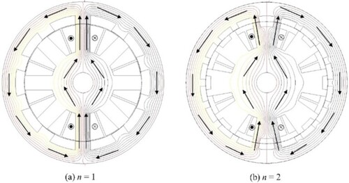
(1) it is evident that, for any given motor size having the same overall dimensions (Dor and Lstk) with a fixed g and magnetomotive force (MMF), the torque output can be enhanced by increasing the value of n. SRM configurations with n = 1 and n = 2 and their corresponding flux patterns have been shown in Figure . The difference in the geometry of the MTSRM, as depicted in Figure (b) (each stator pole is bifurcated into two teeth and Nr is increased accordingly) causes the flux to distribute through each tooth. Further, these flux lines cross the airgap and flow into the corresponding rotor poles. This arrangement results in a larger flux variation over a shorter variation period leading to a higher torque production per electrical period [Citation17].
Figure 1. Flux path comparison of SRM configurations with (a) n = 1 (Conventional SRM) (b) n = 2 (MTSRM).
3. Motor specifications
This section deals with the determination of the motor specifications for the considered E-scooter. The vehicle parameters pertaining to the E-scooter are given in Table . Based on the WMTC [Citation20] and the vehicle parameters, the operating points of the motor are obtained using the vehicle dynamics model delineated by Ehsani et al. [Citation5]. Figure shows the operating points of the E-scooter thus obtained in the WMTC driving cycle. The idealized target peak torque profile consisting of all the operating points is also depicted, assuming a hyperbolic variation above the base speed to establish an idealized constant power range.
Figure 2. Operating points of the E-scooter obtained from WMTC.
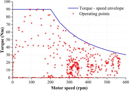
Table 1. Parameters of the E-scooter [Citation21].
Based on this, the design targets with the constraints used for the SRM design are summarized in Table . The SRM designs should primarily target to meet the torque speed trajectory with a maximum torque of at least 90 Nm until the base speed of 200 rpm and a power greater than 1900 W at 600 rpm. It should be noted that the performance requirements of the SRM obtained have been observed to be similar to the performance specifications of the commercially available IW-BLDC motors of the E-scooters in the Indian market [Citation22,Citation23]. Within a 12″ wheel, the motor dimensions having an outer diameter of 278 mm with a stack length between 50–70 mm is a popular choice in the market [Citation10,Citation15]. For the proposed IW-SRM, the stack length is fixed at 65 mm. Given the manufacturing constraint, the air-gap length is set to the lowest attainable value of 0.4 mm. The battery supply voltage is fixed to 48 V. Based on the demand peak load torque at the base speed, the required RMS phase current is calculated and constrained to 75 A (electrical constraint). For SRMs, the ratio between the RMS phase current and the maximum peak phase current lies in the range of 0.3∼0.75 [Citation8,Citation14]. Considering a value of 0.53 in the present case, the maximum peak phase current for chopping is accordingly set to 140 A.
Table 2. Design constraints for the SRM.
4. Methodology
This section discusses the design procedure for the 8/18 MT and the 8/10 SRM topologies. This section also includes some results for the 8/18 MTSRM wherever relevant.
4.1. Electromagnetics design process
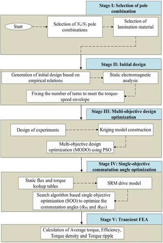
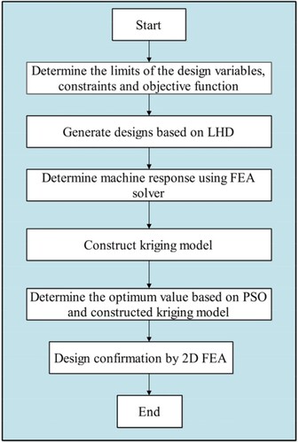
The process employed in the design of the SRM topologies is defined in five discrete stages in the flowchart shown in Figure . Further, the design principles and analysis corresponding to each stage are also discussed. In both the SRM designs considered for comparison, the coils on the diametrically opposite stator poles are connected in series. Four-phase SRMs have been chosen in this study over the lower-phase configurations as they are known to demonstrate improved average torque, power density and lowered torque ripple [Citation8,Citation15]. As SRMs exhibit considerable nonlinearity due to magnetic saturation, FEA is used in this study to accurately analyze their electromagnetic characteristics [Citation10].
Figure 3. SRM design methodology.
4.1.1. Stage I: Selection of pole combination:
Selection of Ns/Nr pole combination: The equation governing the selection of the total number of multi-tooth (Nm), number of multi-tooth per stator pole (n) and the rotor poles (Nr) for the MTSRM is distinct from that followed for the conventional SRMs and is expressed as;
(2)
Selection of core material: M270_35A has been chosen as the core material for both the SRM topologies as it possesses an elevated saturation flux density (2 T) and lower core loss [Citation25]. The B-H curve of the M270_35A is illustrated (Figure ).
Figure 4. B-H curve of M270_35A [Citation25].
![Figure 4. B-H curve of M270_35A [Citation25].](/cms/asset/5cd6f068-7496-440c-bf37-ef91bf6948c7/taut_a_2329492_f0004_oc.jpg)
4.1.2. Stage II: Initial design
Generation of initial design: The classical analytical techniques put forth [Citation17,Citation26] and 2D electromagnetic FEA were used to develop and analyze the initial designs for both the SRM topologies (Figure (a,b)). Constraints to this process include spatial limitation (Dor and L) and g. The different design variables corresponding to both the SRM topologies are indicated in Figure . A description of the design variables has been provided in the nomenclature section of this paper.
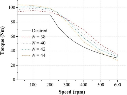
Fixing the number of series turns per phase (N): The number of turns per phase for both the SRM topologies was adjusted to satisfy the peak torque-speed envelope within the constraints of maximum RMS phase current and battery voltage. The procedure put forth by Bilgin et al. [Citation27] was used to achieve this, and it has been illustrated for the 8/18 MTSRM. The static characteristics of the initial design of the 8/18 MTSRM with a varied number of turns per phase (N = 38–44) are obtained using FEA (ALTAIR FLUXTM [Citation28]). These characteristics (i.e. static torque and flux linkage), as lookup tables (LUTs) are then put into the SRM drive model (Figure 8) to determine the optimized commutation angles (θon and θoff). The optimized θon and θoff are obtained using a search algorithm-based SOO intended to maximize the average torque at various speeds. The dynamic results are shown in Figure . For operating speeds lesser than the base speed, it is noted that with the increase in N, the dynamic torque also improves (owing to an increase in the MMF). Beyond the basic speed, these trends, however, reverse because of an increased effective back-emf [Citation29]. Although, it is preferable to use N = 38 or 40 (as the motor exhibited an optimum behaviour i.e. high peak average torque below and above the base speed respectively), N = 42 was selected; the rationale for this is discussed in section 5.1.1.
Figure 5. Initial design of (a) 8/18 MT (n = 2) and (b) 8/10 SRM configurations.
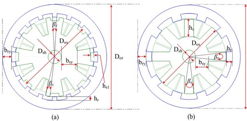
Figure 6. Influence of the number of turns per phase on the dynamic torque of the 8/18 MTSRM.
4.1.3. Stage III: Multi-objective design optimization (MODO) using PSO
For a fair comparison, MODO was performed for both the SRM topologies to determine the optimized values of the design variables. This was executed by coupling the PSO with a Kriging model constructed using the design of experiments (Figure ) [Citation30]. The methodology of the same has been detailed in the author’s previously published work [Citation15]. In the present study, the optimization was intended to maximize the static average torque and minimize the copper loss. Considering a practical range of dimensions of the design variables (depicted in Figure ) for an optimal design, a Latin hypercube design (LHD) was employed in designing the experiments. With the number of turns per phase fixed for each design candidate, the number of strands is maximized to attain a practically attainable slot fill factor of 0.6 [Citation14]. The static average torque (Taverage) for each design candidate at the maximum peak phase current (Ip) is evaluated using 2D electromagnetic static FEA. Taverage is expressed as [Citation8];
(3)
(3) where, ∂W is the magnetic co-energy.
Figure 7. Flowchart of the Multi-objective design optimization.
Peak copper loss (LossCu) is calculated using the expression [Citation15];
(4)
(4) where, Rph is the phase resistance for each design candidate.
Based on the results obtained, Kriging models were generated for both Taverage and LossCu respectively.
The constraints adopted for design variables in the optimization were based on SRM design principles provided [Citation17,Citation26]. The slot fill factor was constrained to 0.6. The MODO model was formulated, wherein the objective function consists of the weighted sum of individual objectives given as;
(5)
(5) where, w1 and w2 are the weight factors for average torque and loss such that
; Taverage and LossCu indicate the average torque and copper loss respectively. Taverageb and LossCub correspond to the baseline values of the average torque and copper loss respectively. w1 and w2 were assumed to be 0.6 and 0.4. A slightly higher weightage is given to average torque as compared to copper loss, to account for the high starting torque requirement in low-speed hill climbing and urban start-stop traffic for the E-scooter application. PSO was employed to determine the optimal solution of Equation Equation5
(5)
(5) .
4.1.4. Stage IV: Single-objective firing angle optimization:
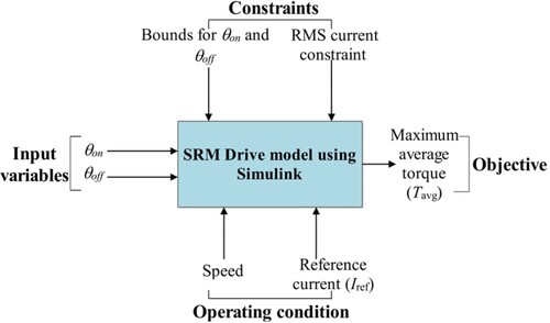
To obtain the dynamic characteristics namely the average torque (Tavg), efficiency (η) and torque ripple (Tripple) of the optimized SRM, it is important to accurately determine the optimized values of commutation angles (θon and θoff) across the torque-speed range [Citation27]. The static characteristics of both the SRM topologies (optimized in stage III) from FEA were fed into the SRM drive model developed in MATLAB/Simulink (Figure ). More details regarding the SRM drive model are provided in [Citation31]. The optimized values of θon and θoff were determined from the SRM drive model by formulating a search algorithm-based SOO to maximize the Tavg [Citation31]. To fully characterize the SRM’s dynamic torque-speed profile, the process was repeated for all the evenly spaced reference current and speed points within the torque-speed range.
Figure 8. Optimization of commutation angles (θon and θoff) using SRM drive model.
During optimization, an RMS phase current limit (Irms_lim) of 75A (Table ) was one of the constraints (non-linear) considered.
(6)
(6) An additional constraint of maintaining a positive Tavg magnitude at all operating speeds and phase currents was also incorporated.
(7)
(7)
The boundaries of the commutation angles (linear constraint) are also listed below;
(8)
(8)
(9)
(9)
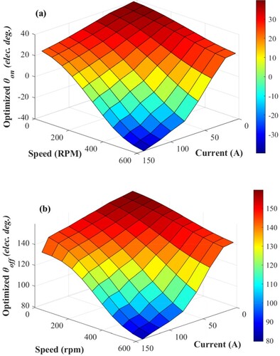
In the present study, the maximum phase conduction angle is set to 120 electrical degrees for both topologies to have an appropriate comparison. The LUTs showing the optimized θon and θoff obtained from the above optimization for the 8/18 MTSRM are depicted in Figure .
Figure 9. LUTs of optimized (a) θon (b) θoff of the 8/18 MTSRM.
4.1.5 Stage V: Transient 2D FEA
The optimized commutation angles (θon and θoff) obtained for various values of reference currents at different operating speeds determined in stage IV for both the SRM topologies were fed into the transient 2D FEA [Citation28] to determine the Tavg, η and Tripple respectively.
η is calculated using the expression;
(10)
(10) where Pout denotes the output power. The loss component (Ploss) consists of both the copper (PCu) and iron core (Pironcoreloss) losses which are given as;
(11)
(11)
PCu is expressed as [Citation14];
(12)
(12) Pironcoreloss, is accurately determined using the loss surface model employed in the transient 2D FEA solver [Citation28].
5. Results and discussions
The optimized design variables and other parameters of both, 8/18 MT and 8/10 SRMs are provided in Table . It should be noted that the number of turns per phase (N) for the 8/18 MTSRM is 42 while that of the 8/10 SRM is 72. The significant reduction in N for the 8/18 MTSRM was mainly due to the MT geometry (n = 2) which produced the desired target torque at a lower MMF (as discussed in Section 2) and is evident. In this section, a comprehensive performance comparison between the two models is drawn based on the results obtained using 2D electromagnetic static and transient FEA.
Table 3. Parameters of the two optimized SRMs.
5.1 Magnetic characteristics
5.1.1. Static torque
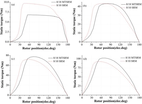
The static torque curves obtained from electromagnetic static FEA for the two topologies at varied phase currents are illustrated in Figure . In this simulation, the currents are maintained constant between the unaligned (0 electrical degrees) and aligned positions (180 electrical degrees). It can be noted that 8/10 SRM produces higher instantaneous torques for a current of 20 A in comparison to the 8/18 MTSRM. The instantaneous torques for 60 A were similar in both designs. However, at higher currents i.e. 100 A and 140 A, 8/18 MTSRM produced higher instantaneous torques.
Figure 10. Static torque of the 8/18 and 8/10 SRM at varied currents (a) i = 20 A (b) i = 60 A (c) i = 100 A (d) i = 140 A.
The average static torque per revolution is calculated from Equation Equation3(3)
(3) . The calculated co-energies (∂W) from the flux linkage curves of the 8/10 and 8/18 MTSRMs were 18.8 and 11.65 J respectively (Figure ). Though the co-energy represents the mechanical output per stroke, average static torque is dependent on the number of strokes per revolution (
in Equation Equation3
(3)
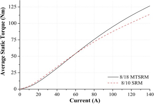
(3) ). Accordingly, the comparison of average static torque for both designs at varied phase currents is depicted (Figure ). The 8/10 design was observed to produce a higher average torque for all values of currents until 50 A. However, a reversal in the trend is noted above 50 A.
Figure 11. Flux linkage curves of the 8/18 MT and 8/10 SRM.
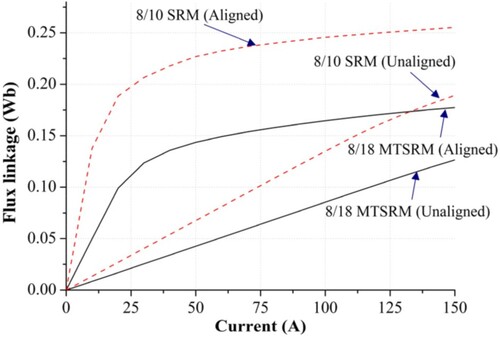
Figure 12. Average static torque of the 8/18 MT and 8/10 SRMs.
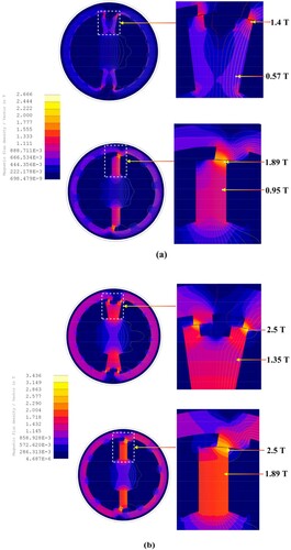
An assessment of the flux densities in the magnetic core of both the SRM topologies at the partially overlapped rotor positions at 20 A and 140 A can be used to explain this behaviour (Figure ). It is known that adequate saturation of the SRM magnetic core, particularly the corners of the stator and rotor poles is essential to enhance the co-energy increment and thereby boost its torque production capability [Citation32]. At 20 A, the average operating flux densities in the stator pole of the 8/10 SRM were higher (∼1.38 T) than the 8/18 MTSRM (∼0.73 T) (Figure (a)). The reduced flux density in the 8/18 MTSRM was due to lower MMF () which was insufficient to cause an adequate saturation of the pole corners in contrast to the 8/10 model (
). The 8/18 MTSRM is thus led to operate in the linear region (0.1–1.2 T) of the B-H curve (Figure ) resulting in decreased co-energy increment and the average static torque subsequently owing to ineffective use of the iron [Citation33]. This can also be deciphered in the flux linkage curves wherein the 8/18 MT and 8/10 SRM begin to saturate at a current of 30 A and 20 A respectively (Figure ). Hence, to improve the saturation level of the 8/18 MTSRM, the number of turns per phase had been maximized to 42 (to maximize the MMF) as compared to 38 and 40 in section 4.1.2, also ensuring that the desired torque-speed envelope is satisfied. At 140 A, 8/10 SRM is under deep magnetic saturation (Figure (b), led to operate in the ineffective use of the current region in the B-H curve) in comparison to the 8/18 MT design thereby resulting in decreased average static torque. The higher average magnetic flux density in the stator pole of 8/10 SRM causes a major part of the MMF to be utilized to push the flux through this segment (due to increased reluctance). This depletes the MMF available to push the flux through the airgap thereby arresting the increase of average torque with increasing current [Citation33,Citation34]. On the other hand, compared to the 8/10 design, the 8/18 MTSRM at 140 A produced a higher average torque due to lower magnetic saturation levels in the stator pole (Figure (b)), indicating that they can demonstrate higher peak torque capacity. The characteristic of MTSRM showing resistance to magnetic saturation as compared to conventional SRM at higher excitation currents was reported by Prasad et al. [Citation35] A reduced magnetic saturation in the 8/18 MTSRM at 140 A indicates that it can be downsized. This can enhance the torque density, a very important consideration for IW motor applications [Citation6].
Figure 13. Flux density of the 8/18 MT and 8/10 SRM at the midway position at (a) 20 A and (b) 140 A.
5.2. Dynamic performance
Though the comparison of the static performance as elucidated previously can indicate the performance to a certain extent, it is imperative to assess the dynamic performance for a comprehensive understanding of the overall characteristics. Moreover, the static analysis considers the phase currents to be constant throughout the half electrical cycle which is not in accord with the practical scenario. In this segment, the dynamic performance of the two SRMs is presented.
5.2.1. Efficiency
The efficiency maps along with their respective copper and iron core losses and RMS currents for both the SRM topologies are depicted in Figures . It was observed that both the designs satisfy the torque-speed envelope as demanded by the E-scooter (Figure ) within the constraints mentioned in Table . The 8/18 MTSRM produced a higher peak torque at lower speeds i.e. below 250 rpm, as they showed higher resistance to magnetic saturation. However, their peak torque output was lower at higher speeds (>250 rpm) as compared to the 8/10 SRM. This was mainly due to the higher number of turns per phase considered (N = 42) for the 8/18 MTSRM which led to an increase in the effective back-emf (Figure ). This limited the rise of the RMS phase current and correspondingly the peak torque above this speed [Citation29]. 8/18 MTSRM exhibited the best efficiency i.e. > 90% between 300 - 600 rpm above 15.5 Nm. The efficiency at the base speed of 200 rpm for the 8/18 SRM was 81.9% while that of the 8/10 SRM was 72.1%. This difference was mainly due to the higher peak average torque (94.1 Nm) and reduced copper loss (363 W) of the 8/18 MTSRM in comparison to the 8/10 SRM (90.9 Nm, 671 W). The phase resistance of the 8/10 SRM was higher (Table ) owing to a higher number of turns per phase considering the available slot area, which led to a higher copper loss. Throughout the envelope, the iron core loss of the 8/18 MTSRM was higher as compared to 8/10 SRM due to an increased stroke frequency. The iron core loss did not have a pronounced effect on the efficiency at the base speed. The 8/18 MTSRM demonstrated superior efficiency than the 8/10 SRM for higher torques for speeds lower than 400 rpm primarily owing to a reduced copper loss.
Figure 14. Comparison of efficiency maps (a) 8/18 MTSRM and (b) 8/10 SRM.
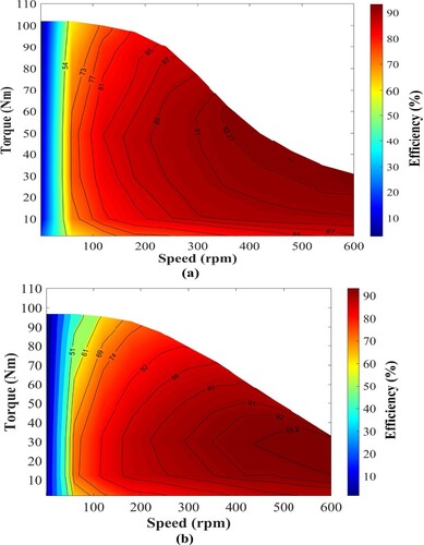
Figure 15. Comparison of copper loss maps (a) 8/18 MTSRM and (b) 8/10 SRM.
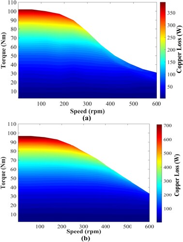
Figure 16. Comparison of Iron loss maps (a) 8/18 MTSRM and (b) 8/10 SRM.
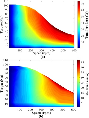
Figure 17. Comparison of RMS current maps (a) 8/18 MTSRM and (b) 8/10 SRM.
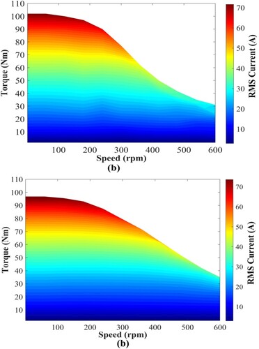
On the other hand, the 8/10 SRM exhibited its maximum efficiency i.e. > 90% in the operating region of 350 - 600 rpm and 11–55 Nm. In comparison to the 8/18 MTSRM, the 8/10 SRM exhibited superior efficiencies in the lower torque ranges (< 11 Nm) across a wide operating speed range. The inferior efficiency of the 8/18 MTSRM in this torque range can be ascribed to its reduced output average torque for lower currents because of inadequate magnetic saturation as discussed previously in Section 5.1.1 and shown in Figure . It is well known that SRMs perform best in terms of output power and efficiency when the stator and rotor poles are sufficiently saturated [Citation33]. An inadequate pole saturation in the 8/18 SRM augmented the RMS current requirement (Figure ) to obtain the desired output average torque, significantly elevating the copper loss. An increased copper loss coupled with a higher iron core contributed to a decrease in the efficiency of the 8/18 MTSRM in this operating range. The above discussion suggests that, within the torque-speed envelope, the 8/10 SRM exhibits favourable efficiencies for lower torque duty cycles whereas the 8/18 MTSRM is more efficient for operating points with larger torque requirements.
Although the 8/18 MTSRM showed higher efficiencies than the 8/10 SRM in most regions of the torque-speed range, a comparison of their drive cycle efficiencies is necessary to discern the suitable SRM topology from an efficiency standpoint for the E-Scooter. The drive cycle efficiency (ηcycle) can be evaluated by dividing the summation of the output power and the summation of the input power at each operating point (j) of the driving cycle, which is expressed as [Citation36];
(13)
(13) where, K indicates the number of operating points, Pout,i and Ploss,i indicates the output and the total loss at each operating point j. Accordingly, the ηcycle are calculated by running both the SRM topologies over the WMTC (Figure ). A gridded interpolation is carried out in MATLAB over the operating speed, phase current, and losses to determine the losses at each operating point. The drive cycle efficiency of the 8/18 MTSRM was calculated to be 89.75% while that of 8/10 SRM was 87.94%. Although the difference in ηcycle is not particularly substantial, an improvement of just 1.81% can significantly reduce energy consumption.
5.2.2. Steady-State characteristics of the motors
In this segment, the steady-state characteristics of the two motors have been compared at 200 and 600 rpm using transient FEA simulation. The vital performance parameters of both the motors obtained are enlisted (Table ). The torque and current waveforms for both the SRM configurations with current chopping control (CCC) at the speed of 200 rpm are depicted in Figure . The chopping current was set to 140 A and the optimized commutation angles determined previously (Section 4.1.4) were used for simulation (θon= 0.15°,0.71° and θoff = 6.82°,12.71° mechanical angles for the 8/18 MT and 8/10 SRM respectively). The conduction angles of the two SRMs were set to 120 electrical degrees for a fair comparison. Of the two design topologies evaluated, the average torque (Tavg) was higher in the 8/18 MTSRM (∼3.52% higher) due to a lower saturation which also corroborates the static performance trends described in Section 5.1. Figure shows the torque and current waveforms with single-pulse control (SPC) at the maximum speed of 600 rpm (θon = −2.35°,−5° and θoff = 4.32°,7° mechanical angles for the 8/18 MT and 8/10 SRM respectively). The 8/18 MTSRM produced a lower average torque owing to an increased effective back-emf as compared to the 8/10 SRM (delineated in Section 5.2.1). A drop in the RMS phase current and the corresponding torque, caused by an increased effective back-emf for the 8/18 MTSRM can be noted (Table ). The 8/18 MTSRM exhibited higher power and specific torque at lower speeds. While, at higher speeds, the 8/10 SRM showcased better power and specific torque characteristics. Further, the 8/18 MTSRM demonstrated a lower torque ripple (Tripple) (25.46%) as compared to the 8/10 SRM (41.61%). The decreased torque ripple exhibited by the 8/18 MTSRM is mainly due to the increased number of strokes per revolution which reduces the torque dips during commutation between the phases (also evident from instantaneous torque profiles in Figures and ).
Figure 18. Torque and current waveforms operating on CCC at 200 rpm.
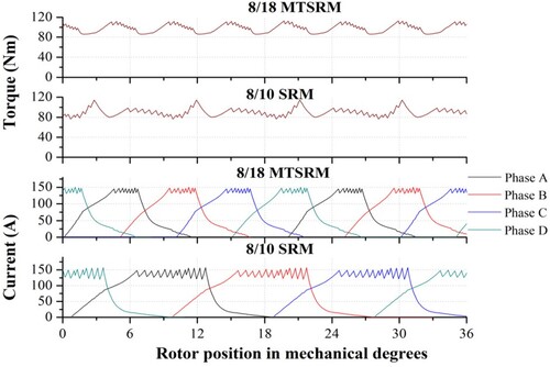
Figure 19. Torque and current waveforms operating on SPC at 600 rpm.
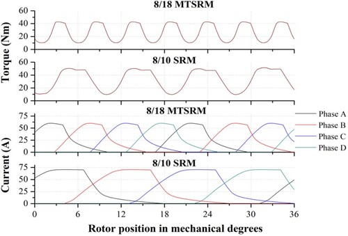
Table 4. Comparison of steady-state performance of two SRM topologies.
For the E-scooter application, the 8/18 MTSRM was chosen as it offered an optimum balance between starting torque (higher peak torque at lower speeds), drive cycle efficiency and torque ripple. Although its peak torque output is lower at higher speeds (>250 rpm) as compared to the 8/10 SRM, it satisfied the desired torque-speed envelope as demanded by the E-scooter.
Figure 20. 2D FEA thermal model of the 8/18 MTSRM.
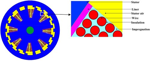
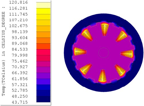
5.3. Thermal analysis
The thermal capability is the second most vital constraint following their electromagnetic performance. The thermal performance of the chosen 8/18 MTSRM configuration has been determined by using a 2D FEA thermal model built in ALTAIR FLUX [Citation28] at the base speed (200 rpm) for the maximum operating current. The stator slot in the FEA model comprises of slot liners, impregnation, and copper wire along with its insulation (Figure ). The heat sources namely the copper loss (being dominant) and iron loss obtained from the transient FEA carried out previously are the load inputs for this simulation. The initial motor temperature is fixed at 40°C. The temperature constraint of the windings is set to be 120°C (“Class E” wire is considered in this analysis). The simulation result presented in Figure shows the time required for the windings of the chosen 8/18 MTSRM to attain the peak temperature of 120°C at the base speed. Under such highly loaded conditions, the peak temperatures of the windings in both motors can remain below 120°C for about five minutes which is quite adequate [Citation14]. Considering this, the thermal performance of the 8/18 MTSRM can be concluded to be satisfactory. The temperature field model of the 8/18 MTSRMs after five minutes of running at 200 rpm at the maximum phase current is shown in Figure . It can be observed that the temperature of the windings was the highest among all the machine segments.
Figure 21. Temperature rise of the windings for peak torque condition at 200 rpm.
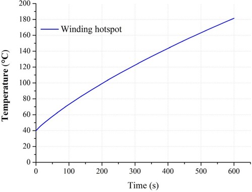
Figure 22. Temperature distribution of the 8/18 MTSRM after five minutes of running at 200 rpm.
6. Experimental validation of the FEA model
For experimental validation of the FEA model used in this study, a downsized prototype of the 8/18 MTSRM (Figure ) was manufactured, and its specifications are listed in Table . 3-D FLUX analysis of the design is carried out, wherein winding end-turns and the axial field fringing effects are considered. The 3D-FEA model for the aligned position is depicted in Figure .
Figure 23. (a) MT Stator (b) MT Stator with the phase coils and rotor (c) Assembled 8/18 MTSRM prototype.
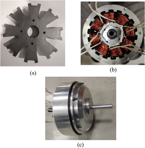
Figure 24. 3D-FEA model of the downsized 8/18 MTSRM.
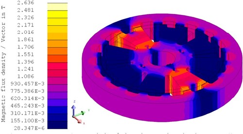
Table 5. Parameters of the 8/18 MTSRM prototype.
The flux linkage characteristics of the 8/18 MTSRM prototype were experimentally validated using the methodology described by Song et al. [Citation37]. The experimental platform depicted in Figure . The rotor was clamped at the unaligned and the aligned position using a mechanical locking system and a current pulse was injected into one of the phases at different current amplitudes using a DC power supply. The positioning of the rotor at the unaligned and aligned position was incorporated using a stepper motor mechanically coupled to the SRM shaft. The precision of this process was ensured by measuring the angular position of the rotor by employing an absolute rotary encoder mounted on the stepper motor shaft and connected to NI-9401 DAQ. For each rotor position and the phase current, the rising current and the corresponding phase voltage (Figure (a,b)) were measured using a current probe (Tektronix A622) connected to NI-9215 and NI-9227 voltage DAQs respectively. The flux linkage (ψ) was computed using the expression [Citation26];
(14)
(14) where, V corresponds to instantaneous voltage across the phase winding, t1 corresponds to the time instant when the magnitude of current reaches the value i and R is the phase resistance.
Figure 25. Experimental platform for determining the flux linkage of the 8/18 MTSRM prototype.
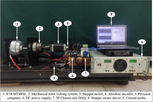
Figure 26. Measured current and voltage at (a) Unaligned, (b) Aligned position and (c) 3D FEA simulation and measured flux linkages for the 8/18 MTSRM.
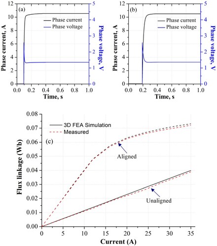
Figure (c) shows the comparison between the 3D FEA simulated and measured phase flux linkages of the 8/18 MTSRM at the unaligned and the aligned rotor positions. The measured flux linkages at these positions are marginally lesser than that of 3D FEA primarily because of manufacturing deviations of the prototype motor. However, the percentage error between the 3D-FEA simulation and the measured flux linkages is less than 5%, thus indicating the correctness of the FEA model.
7. Conclusion
In this paper, a comprehensive electromagnetic performance comparison has been carried out between a novel four-phase 8/18 MT and the conventional 8/10 SRMs within the same geometrical and electrical constraints across the full torque-speed range. Both the SRM designs were compared based on magnetic characteristics, efficiency and steady-state operation. For a fair comparison, the design variables of the SRMs were optimized using multi-objective PSO. Further, to accurately optimize the commutation angles across the torque-speed plane, a computationally efficient SRM drive model was employed. Based on the results obtained, the following conclusions can be drawn;
The number of turns per phase required to satisfy the torque-speed envelope for the 8/18 MTSRM was significantly lesser compared to the 8/10 SRM (71.45% lesser). A reduction in the number of turns per phase indicated that the 8/18 MTSRM required a lower MMF to produce the target torque. These findings corroborated the concept of MT topology.
Owing to a reduced MMF, the average static torque of the 8/18 MTSRM in comparison to the 8/10 SRM was lower for phase currents below 50 A majorly due to inadequate magnetic saturation of the pole corners. Above 50 A, a reversal in the trends was observed. At the maximum phase current (140 A), 8/18 MTSRM exhibited a higher average static torque (11.21% higher) which was attributed to lower magnetic saturation levels in the stator pole as compared to the 8/10 SRM, thus indicating higher peak torque capacities. This indicates that the proposed design can be downsized to boost its torque density, a design consideration paramount for an IW motor.
Within the geometrical and electrical constraints, both the proposed 8/18 MT and the conventional 8/10 SRMs satisfied the torque-speed envelope demanded by the E-scooter application. Since the 8/18 MTSRM was highly resistant to magnetic saturation, the topology produced a higher torque at lower speeds (below the base speed). Above the base speed, their torque output was lower owing to a higher effective back-emf.
The 8/18 MTSRM exhibited superior efficiencies at operating points with higher torque duty cycles while the 8/10 SRM demonstrated its highest operating efficiencies in the lower torque range. 8/18 MTSRM illustrated a greater drive cycle-oriented efficiency (∼1.81% higher) than the 8/10 SRM.
Results from the steady-state analysis indicated that the 8/18 MTSRM exhibited higher average torque (3.52% higher) and specific torque (5.15% higher) at the base speed. While at the maximum speed, it produced a lower average torque (7.17% lower) and specific torque (5.18% lower) due to a higher effective back-emf. The above results indicate that the 8/18 MTSRM is suitable for greater torque drive cycles and lower speeds while the 8/10 SRM is favoured for lowered torque requirements and higher speeds. Further, the 8/18 MTSRM demonstrated a lower torque ripple percentage (38.8% lower) at the base speed.
For the E-scooter application, the 8/18 MTSRM was chosen as it provided an optimum balance between peak torque capacity, drive cycle efficiency, and torque ripple along with acceptable thermal performance.
Further, the FEA model used in this study is validated experimentally on a downsized 8/18 MTSRM prototype with less than 5% error.
The obtained results indicate that the 8/18 MTSRM is a novel solution as it exhibited a higher peak torque capacity, torque density and superior efficiencies in most operating regions with a reduced torque ripple. This makes it a strong contender for in-wheel applications in the future.
Acknowledgment
The research was performed in the Centre for System Design at the National Institute of Technology Karnataka, Surathkal, and is supported by the Ministry of Heavy Industries, Government of India under its project titled ‘Switched Reluctance Motor for 2W and 3W’ on the TPEM and FAME – India scheme [Grant no – F.No. 3(5)/2018-NAB-II(AUTO) (20331)].
Disclosure statement
No potential conflict of interest was reported by the author(s).
Data availability statement
All necessary data and material can be made available.
Authors contribution
The authors contributed to the conception of the study, analysis and data interpretation, drafted the work and critically reviewed it. The authors’ agreed to be accountable for all aspects.
Consent to publication
The authors have obtained consent from the responsible authorities of National Institute of Technology Karnataka, Surathkal before the work has been submitted.
Additional information
Funding
References
- Das PK, Bhat MY. Global electric vehicle adoption: implementation and policy implications for India. Environmental Science and Pollution Research. 2022;29:40612–40622. doi:10.1007/s11356-021-18211-w
- Malik L, Tiwari G, Thakur S, et al. Assessment of freight vehicle characteristics and impact of future policy interventions on their emissions in Delhi. Transp Res D Transp Environ. 2019;67:610–627. doi:10.1016/j.trd.2019.01.007
- Singh V, Singh V, Vaibhav S. Analysis of electric vehicle trends, development and policies in India. 2021.
- EV sales. Available: https://www.smev.in/ev-sales, accessed Oct. 2022.
- Modern Electric. Hybrid Electric, and Fuel Cell Vehicles Third Edition.
- Xue XD, Cheng KWE, Ng TW, et al. Multi-objective optimization design of in-wheel switched reluctance motors in electric vehicles. IEEE Trans Ind Electron. 2010;57:2980–2987. doi:10.1109/TIE.2010.2051390
- Xuan J, Wang X, Lu D, et al. Research on the safety assessment of the brushless DC motor based on the gray model. Advances in Mechanical Engineering. 2017;9; doi:10.1177/1687814017695438
- Miller TJE. Switched reluctance motors and their design. Oxford: Magna physics publishing and Clarendon Press; 1993.
- Ananda Padmanaban L, Saravanan P. Design, analysis and comparison of switched reluctance motors for electric vehicle application. Automatika. 2023;64:239–247. doi:10.1080/00051144.2022.2140388
- Singh VK, Sharma U, Singh B. Design and validation of SR motor for direct drive In-wheel using ansys simplorer. 2021 IEEE 6th International Conference on Computing, Communication and Automation, ICCCA 2021. pp. 914–919. Institute of Electrical and Electronics Engineers Inc. 2021.
- Vandana R, Nikam S, Fernandes BG. Criteria for design of high performance switched reluctance motor. Proceedings - 2012 20th International Conference on Electrical Machines, ICEM 2012. pp. 129–135. 2012.
- Desai PC, Krishnamurthy M, Schofield N, et al. Novel switched reluctance machine configuration with higher number of rotor Poles than stator Poles: concept to implementation. In: IEEE transactions on industrial electronics. 2010. p. 649–659.
- Lin J, Schofield N, Emadi A. External-Rotor 6-10 switched reluctance motor for an electric bicycle. IEEE Trans Transp Electrification. 2015;1:348–356. doi:10.1109/TTE.2015.2502543
- Howey B, Bilgin B, Emadi A. Design of an external-rotor direct drive E-bike switched reluctance motor. IEEE Trans Veh Technol. 2020;69:2552–2562. doi:10.1109/TVT.2020.2965943
- Sandesh BB, Jogi A, Pitchaimani J, et al. Design and optimization of an external-rotor switched reluctance motor for an electric scooter. Mater Today Proc. 2023. doi:10.1016/j.matpr.2023.03.696
- Nikam SP, Rallabandi V, Fernandes BG. A high-torque-density permanent-magnet free motor for in-wheel electric vehicle application. IEEE Trans Ind Appl. 2012;48:2287–2295. doi:10.1109/TIA.2012.2227053
- Zhu J, Cheng KWE, Xue X, et al. Design of a new enhanced torque In-wheel switched reluctance motor With divided teeth for electric vehicles. IEEE Trans Magn. 2017;53:1–4. doi:10.1109/tmag.2017.2703849
- Farahani EF, Mirsalim M. Comprehensive study on divided-teeth and permanent magnet assisted outer-rotor switched reluctance motors. IET Electr Power Appl. 2020;14:2293–2300. doi:10.1049/iet-epa.2020.0189
- Davarpanah G, Mohammadi S, Lang JH, et al. Two-phase switched reluctance motor with hybrid excitation: modeling and evaluation. IET Electr Power Appl. 2023;17:939–951. doi:10.1049/elp2.12316
- Steven H. Worldwide harmonised motorcycle emissions certification procedure. Dec. 2002. Available: https://unece.org/DAM/trans/doc/2003/wp29grpe/TRANS-WP29-GRPE-45-inf09e.pdf, accessed Dec. 2022.
- Andrada P, Martínez E, Blanqué B, et al. New Axial – Flux Switched Reluctance Motor for E-Scooter. 2016.
- BGauss B8 electric scooter. Available: https://www.bgauss.com/b8-overview/, accessed Jun. 2023.
- Hero electric photon electric scooter. Available: https://www.google.com/amp/s/www.bikedekho.com/hero-electric/photon-48v%3famp=1, accessed Jun. 2023.
- Zhu J, Cheng KWE, Xue X. Torque analysis for in-wheel switched reluctance motors with varied number of rotor Poles. 2016 International Symposium on Electrical Engineering, ISEE 2016. Institute of Electrical and Electronics Engineers Inc. 2017.
- M270_35A. https://perso.uclouvain.be/ernest.matagne/ELEC2311/T2006/NOFP.pdf. Accessed on 25th September, 2023.
- Krishnan R. Switched reluctance motor drives: modeling, simulation, analysis, design, and applications.
- Bilgin B, Jiang JW, Emadi A. Switched reluctance motor drives: fundamentals to applications. Boca Raton (Florida): CRC Press; 2018.
- Altair Flux. Package for electromagnetic and thermal analysis using finite elements FLUX 2D and FLUX 3D, Version 2021, Bangalore, India https://www.altair.com/flux/.
- Chiba A, Takeno M, Hoshi N, et al. Consideration of number of series turns in switched-reluctance traction motor competitive to HEV IPMSM. IEEE Trans Ind Appl. 2012;48:2333–2340. doi:10.1109/TIA.2012.2227093
- Ma C, Qu L. Multiobjective optimization of switched reluctance motors based on design of experiments and particle swarm optimization. IEEE Trans Energy Convers. 2015;30:1144–1153. doi:10.1109/TEC.2015.2411677
- Pillai A, Anuradha S, Gangadharan KV, et al. Modeling and analysis of average torque control strategy on switched reluctance motor for E-mobility. Proceedings of CONECCT 2021: 7th IEEE International Conference on Electronics, Computing and Communication Technologies. Institute of Electrical and Electronics Engineers Inc. 2021.
- Jiang W, Moallem M, Fahimi B, et al. Qualitative investigation of force density components in electromechanical energy conversion process.
- Rahmani O, Sadrossadat SA, Mirimani SM, et al. Optimization of efficiency and output power of 8/6 switched reluctance motor using new neural network-based adjoint L p metric method. IET Electr Power Appl. 2021;15:769–783. doi:10.1049/elp2.12073
- Bhaktha S, Kumawat S, Pitchaimani J, et al. Design and performance analysis of a switched reluctance motor using finite element analysis and magnetic equivalent circuit model. Def Sci J. 2023;73:29–40. doi:10.14429/dsj.73.1.17828
- Prasad N, Jain S, Gupta S. Comparative analysis of new improved force split-teeth linear switched reluctance motor for high speed transit systems. Sådhanå. 2020: 147. doi:10.1007/s12046-020-01389-zS
- Carraro E, Morandin M, Bianchi N. Traction PMASR motor optimization according to a given driving cycle. IEEE Trans Ind Appl. 2016;52:209–216. doi:10.1109/TIA.2015.2477479
- Song S, Ge L, Ma S, et al. Accurate measurement and detailed evaluation of static electromagnetic characteristics of switched reluctance machines. IEEE Trans Instrum Meas. 2015;64:704–714. doi:10.1109/TIM.2014.2358132