
 ?Mathematical formulae have been encoded as MathML and are displayed in this HTML version using MathJax in order to improve their display. Uncheck the box to turn MathJax off. This feature requires Javascript. Click on a formula to zoom.
Abstract
This paper presents a new control method for surge instability of the compressor system. Due to the importance of the active control approach in improving the efficiency of the compressor system, a new scheme based on the model predictive control (MPC) technique has been considered to control surge which gives the benefits of control signal optimization by considering the constraints on states and input. Because of designing a novel MPC by using of linear matrix inequality scheme, the optimization problem is solved in less time and with less complexity. The proposed method is able to consider the limitation of the close coupled valve actuator and also covers the uncertainty on the model. In addition, the developed model describes the nonlinear behaviour of the compressor system and handles the effects of the pipe on surge instability. Using Lyapunov theory, the stability of the closed-loop system under the proposed robust active controller is shown. The simulation results show the high pressure and high efficiency operation of the system under study in different operating conditions.
Nomenclature
| MPC | = | Model predictive control |
| NMPC | = | Nonlinear model predictive control |
| LMI MPC | = | Linear matrix inequality model predictive control |
| CCV | = | Close coupled valve |
| = | Compressor mass flow | |
| = | Compressor pressure rise | |
| = | Plenum mass flow | |
| = | Plenum pressure rise | |
| = | Close coupled valve mass flow | |
| = | Throttle valve mass flow | |
| = | Throttle valve pressure rise | |
| = | Impeller velocity | |
| = | Air density (kg/m3) | |
| = | The cross sectional area of the compressor duct | |
| = | The inlet absolute pressure | |
| = | The density at the inlet | |
| = | Helmholtz frequency | |
| = | The Greitzer stability parameter | |
| = | Valve constant | |
| = | The ccv opening percentage | |
| = | The characteristic curve correspond to the stable flow region of the compressor | |
| = | The characteristic curve correspond to t unstable flow region | |
| = | Upstream (plenum) pressure and volumetric flow rate | |
| = | Downstream (throttle duct) pressure and flow rate. | |
| = | The throttle valve opening percentage | |
| = | The valve constant |
1. Introduction
Centrifugal compressors are used in turbochargers, petrochemicals, aerospace, power plants and turbo shaft gas turbine engines due to their high pressure ratio, extensive operational range and cost benefits. They are usually engine or turbine driven and their widespread use is mostly due to smooth operation, high tolerance of process fluctuations and higher reliability compared to other types of compressors. These devices are an integral part of the industry, and any malfunction in their operation can cause upstream and downstream equipment failure. Due to the special place of compressors in industrial energy consumption, many efforts are being made to ensure the stable and optimal performance of these devices simultaneously [Citation1–3]. The performance of the compression system depends on the performance curve of compressor and its connected downstream and upstream equipment.
Various limitations affect the performance of the compressor system, the most important of which are: surge, stall and choke. Despite the negative effects of all these instabilities, surge, as the most destructive phenomenon, can cause severe mechanical damage to the compressor system and take it out of the circuit, and is therefore of particular importance. Compressor surge is a type of aerodynamic instability in axial or centrifugal compressors. The term refers to the intense airflow that oscillates in the axial direction of the compressor, indicating that the axial component of the fluid velocity changes intermittently and may even become negative. This is a fundamental dynamic instability that affects the all-inclusive compressor system and can cause high thermal and mechanical stresses in the system and cause severe damage to the compressor and its accessories. In addition, surge fluctuations can lead to unacceptable noise levels. Therefore, designing a suitable surge controller is essential for the compressor system.
Having a real model of the compressor system, considering the effect of different components on its dynamic behaviour, is the most important step in scheming a suitable controller. Over the years, several mathematical models have been proposed to describe the flow dynamics in compressor systems. Greitzer presented a dynamic model for the compressor system, compared its behaviour with real system, and evaluated the effect of different model parameters [Citation4,Citation5]. After Greitzer's worthy effort, the model and physics in [Citation6] concluded that the geometric accuracy and characteristics of the compressor are the two main issues in model development for the main compressor system. To evaluate the influence of different parts on surge oscillation, the effect of pipe on the stability of the compressor system was investigated in [Citation7,Citation8]. Spark and Brown showed that the pipe system connected to the compressor has a very important role in the stability of the compressor system and can lead to strengthening and accelerating the occurrence of surge and, of course, limiting the stability range of the compressor. Accordingly, this paper presents a control-oriented model for the compressor system that, along with a description of the system state space, considers the effects of piping and the CCV actuator.
There are two main categories for compressor system surge controllers, which include passive and active control approaches [Citation9,Citation10]. Extensive efforts to increase efficiency, reliability and performance range have led to significant advances for controlling the surge instability of the compressor system. Passive control methods or surge avoidance methods, despite their high reliability and widespread use in existing compressor systems, are no longer the preferred method in designing new compressor systems, as they reduce system efficiency and sacrifice operating range. The active control method, despite reducing reliability, extends the compressor operating range to less mass flows. The use of this scheme has been highly regarded due to the importance of energy optimization and increasing efficiency, and various actuators have been used in this regard. Active surge control makes the compressor system much more flexible and allows the machine to perform more efficiently, usually near the surge line.
Among the various actuators used in the design of surge controllers, the close coupled valve is the most common actuator used in the compressor systems of the oil and gas industry due to its high speed and suitable performance [Citation11,Citation12]. Another aim of this study is to cover the physical limitations governing CCV actuator, while most active control techniques introduced to date [Citation13,Citation14] have not considered these important and fundamental restrictions. Given that there is a certain range for flow and pressure of different parts of the compressor system, considering the constraints in the states is another goal in the design of the controller. Also, the next goal is to consider the uncertainty that results from the uncertainty in the percentage of throttle valve opening and of course the uncertainty in modelling.
To the best of the authors’ knowledge to date, only a handful of surge controllers have been designed with pipe effects in mind. The controller designed in [Citation15] is not able to capture the completely nonlinear dynamics of the compressor system and another disadvantage is the low operating range. Also, the control method designed in [Citation16] despite the numerous advantages, suffers from a high computational volume and, of course, is not able to guarantee stability in the presence of uncertainty. In view of the above and considering the ability and application of predictive and robust methods in different applications [Citation17–20], this paper presents a novel robust model predictive control approach by using of LMI to control the surge instability of the compressor system in the presence of uncertainty and includes the following innovations: (1) Considering the nonlinear model of compressor system. Due to the various components affecting the behaviour of the compressor, it is necessary to consider its nonlinear model; (2) Considering the effects of pipe on surge instability. The downstream pipe connected to the compressor has a significant effect on the operating range of the compressor and the displacement of the surge line; (3) Providing robust control scheme based on LMI. The LMI-based model predictive control technique, in addition to reducing computational volume, offers the ability to online executing simultaneously with optimization; (4) Ensuring stability in the presence of model and throttle valve uncertainties; The proposed technique is able to ensure stability and surge-free operation in the presence of uncertainty in the model and in addition has the ability to deal with changes in the throttle valve; (5) Considering the limitations of the CCV actuator and system states; An important advantage of the planned scheme is the ability to satisfy the constraints on the compressor system states and to fulfil the actuator limitations.
Therefore, this paper is organized as follows: The second part considers the dynamic model of a compressor system consisting of several compressors and considering their interactions with each other, offers the state space model that includes the effects of piping and nonlinear terms. In the third part, for the working class of the compressor system, a new MPC controller based on LMI is presented and then the stability of the closed loop system is guaranteed under the proposed method. In the fourth section, the simulation results are presented and the results are compared and evaluated. Finally, the fifth section includes conclusions and suggestions for future studies.
2. The model of compressor system
This research focuses on multi-compressor compression systems. To achieve the required pressure increase in a typical gas processing system in Iran, the fluid first enters the compression system duct. The compression system uses a bank of constant speed compressors to raise the fluid pressure to the required level and deliver it directly to the transmission areas. Figure shows a schematic of a sample system with three compressors, including two parallel compressors and a series compressor with the same specifications. According to [Citation11] in the compression system, the recycle valve is considered as the actuator for each compressor. The fluid is amplified in two parallel compressors and then sent to the third compressor. For more reliability, the Spill Back is envisaged as a safety valve for the system that causes the compressors to interact.
Figure 1. Schematic of a sample system with three compressors.
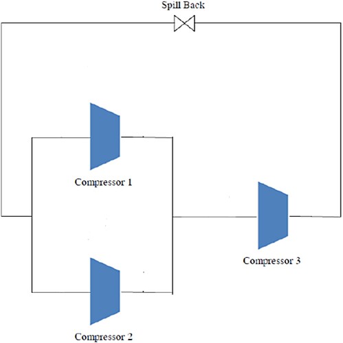
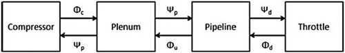
Figure shows a block diagram of the various components of each compressor, while its corresponding dynamics are fully described in reference [Citation15]. According to the characteristics of the Spill Back valve, the correlation between the flow of the Spill Back valve and the pressure of the third compressor throttle (
) in the compressor system of Figure is as follows.
(1)
(1) Where,
indicates the valve’s gain.
Figure 2. Block diagram of each compressor with pipeline dynamics.
In the resulting nonlinear system, indicates the compressor mass flow,
specifies the plenum pressure rise,
states the throttle section pressure rise and
shows the plenum mass flow rate. As stated by Figure , the state space equations for the compression system with two parallel compressors and one serial compressor are like this:
(2)
(2) Where
and
. The corresponding matrix coefficients of the piping equation in (2) are found to be
,
,
,
,
and
. The parameters of the compressor system model used in this study are given in Table .
Table 1. Model parameters for the compression system.
An Euler approximation of system (2) with sampling time equals to
(3)
(3)
Which is a subset of discrete nonlinear systems as follows
(4)
(4)
The next section provides a robust LMI-based MPC for this compressor system. The parameters of the theoretical model can be found in .
3. The proposed robust model predictive control by using of linear matrix inequality
This section presents the robust model predictive control formulation for the work class introduced in the previous section. The basis for ensuring the stability of the proposed controller is based on the fact that first a proof of stability process is presented for one of the agents and the working class under study, and since this process can be generalized to all agents, the stability of the overall closed-loop system in the presence of all agents can be imagined despite all the interactions of agents on each other and other inconveniences.
Consider a discrete-time nonlinear system of one of the agents as
(5)
(5) Where
and
are coefficient matrices,
indicates the control input conditional on
specifies the state of the system bound by
and
satisfies a Lipschitz condition and
function (
is the equilibrium of the system). The MPC scheme is used to find state feedback by minimizing an objective function to optimize closed-loop system performance over an optimal time horizon. Based on measurements obtained from the plant, the calculations are repeated at subsequent sampling times. To determine the control law
of system (5), the objective function is defined as follows
(6)
(6) Where
signifies state at time
founded on the measurements at time
and
indicates control signal at time
calculated by minimizing
at time
.
To obtain optimization problem solution for the nonlinear system in (5) through linear matrix inequality, first, the upper limit of is substituted in Equation (6) to obtain the desired inequality. By supposing a quadratic function
with
and
, the following inequality holds at sampling time
(7)
(7)
It is obtained by summing both sides of (7) from to
(8)
(8) Where
indicates a positive scalar and it is an upper boundary for (6). Consequently, the robust model predictive control problem is defined in the following.
Theorem 3.1:
Suppose be the measured state
at sample time
in system (5) conditional on
and
. Then, the state feedback
in the control law
is gotten by
. Matrix
minimizes the upper boundary of
in the objective function
at time instant
, and
and
are achieved from the solution of the subsequent optimization problem with variables
and
and
indicates a positive coefficient.
(9)
(9) Conditional on
(10)
(10)
(11)
(11)
(12)
(12)
(13)
(13)
(14)
(14)
Proof:
the following lemma is used to establish the proof of Theorem 3.1.
Lemma 3.1:
Suppose and
are real constant matrices and
is a positive matrix of compatible dimensions. Then
holds for any
.
Proof:
See . [Citation21]
Applying Schur complements to in (8) and replacing
, relation (10) is derived. To obtain (11), relation (7) is rewritten as
(15)
(15)
Considering Lemma 3.1, the following inequality can be found for the first term in (15).
(16)
(16)
According to (
indicates the largest Eigen value of
) and by using of (16), relation (15) can be stated as.
(17)
(17)
Replacing , relation (17) holds for every
if and only if
(18)
(18) is fulfilled. Let
and
and by pre and post multiplying (18) by means of
and then applying Schur complements, it can be obtained
(19)
(19)
According to , (19) is guaranteed every time (11) is fulfilled. Considering , relation (11) can be rewritten as follows.
(20)
(20)
The inequality denotes that component in (20) should be a positive semi-definite matrix. On the other hand, since
then
is true, equivalent to
(21)
(21)
By considering (21), relation (20) can be written as.
(22)
(22)
The relation (19) is gotten from (22) by pre-multiplying it by diag and post-multiplying by diag
. The condition
and replacing
and
results in (12).
In Theorem 3.1, relation (10) states that and (11) indicates that
is a decreasing function or equivalently
for
. Thus,
fits in an invariant set
. If there exists a symmetric matrix
in a way that
, then relation (13) assurances the state constraints fulfilment in Theorem 3.1.
For driving (14), consider (10) and the fact that fit in an invariant set
. Then input limitation can be described as
(23)
(23)
It can be achieved by using of Cauchy–Schwarz inequality
(24)
(24)
So if there exists a symmetric matrix such that
and
(25)
(25)
Then the input limitations in Theorem 3.1 are guaranteed. Bearing in mind (19), (25) is assured if (14) holds.
In the same way, the proof process presented for one of the agents can be generalized to all agents and stability with the same design can be achieved for all agents.
Thus for the nonlinear system in (5), RMPC based on Theory 1 can asymptotically stabilize the closed-loop system with the estimated region where
is achieved from
conditional on (11)–(14).
4. Simulation results and discussion
In this section, simulation in MATLAB environment is used to show the ability of the proposed predictive approach to control surge instability, cover uncertainty effects as well as high efficiency performance. The scenario is as follows: the entire simulation occurs in one second. Up to ,
is equal to
and after this time
is considered equal to
. Also in this simulation up to
,
is considered as a nominal value, while after this time a tolerance of
is embedded on
. Also, for better evaluation, the results obtained using the proposed robust scheme have been compared with the NMPC and Tube-MPC techniques [Citation16,Citation22]. These techniques are nominal model dependent and do not cover any structural uncertainties. Of course, the NMPC technique cannot guarantee stability in the event of uncertainty, but it has been used to better compare and demonstrate the controller capability.
The simulation results are described below and the comparative results are plotted. The diagrams of compressor mass flow, plenum pressure increment, throttle pressure increment and plenum mass flow are shown in Figures . Figure also shows the control signal obtained from the two NMPC and proposed robust LMI MPC techniques.
Figure 3. Compressor Mass Flow.
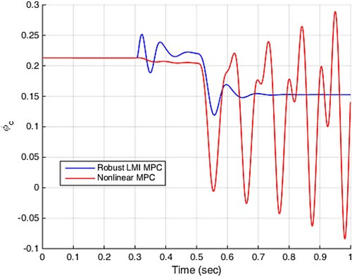
Figure 4. Plenum pressure.
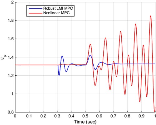
Figure 5. Throttle pressure.
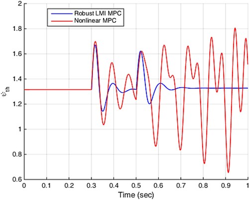
Figure 6. Plenum mass flow.
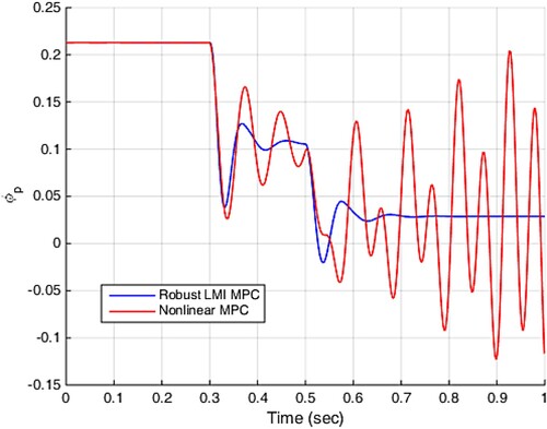
Figure 7. Control Signal.
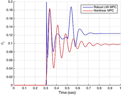
As shown in Figures , by changing the at
, the operating point of the compressor system starts to change and moves to the new situation, and at the same time, NMPC and LMI-MPC controllers apply control signals to the compressor system by performing optimization. This process leads to limited changes in the compressor system states under the NMPC technique and, of course, milder changes occur in the compression system states under the proposed LMI MPC scheme, while at this stage both controllers prevent surge instability. The next inconvenience considered in this simulation, i.e. 25% uncertainty on
, leads to further change in the behaviour of the compressor system states. Examination of the simulation results in Figures shows that from
the all compressor system states fluctuates sharply under NMPC approach, while under the proposed robust LMI MPC technique, the compressor system states reach a new equilibrium point with optimal operation without surge instability despite drastic changes, and from
onwards, no oscillations are observed on the system states. The changes in the control signal shown in Figure indicate the possibility of control signal to ensure compressor stability and surge-free operation.
The results obtained by applying the proposed LMI MPC and Tube-MPC approaches are now compared and shown in Figures . Although the Tube-MPC compressor does not experience negative flow, but a sharp drop occurs and the compressor operating point rapidly tilts toward the surge area, as shown in Figure . However, the current under the proposed LMI MPC method is far from the surge area and in stable operation mode.
Figure 8. Compressor mass flow.
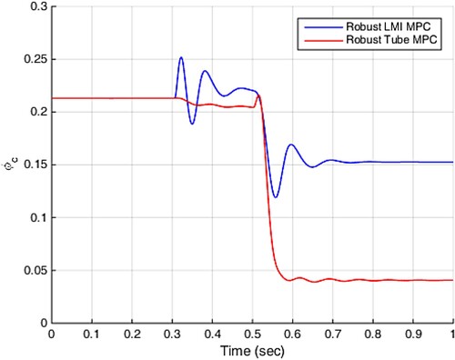
Figure 9. Plenum pressure.
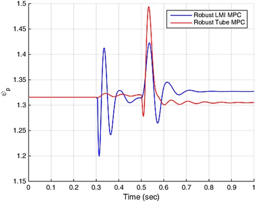
Figure 10. Throttle pressure.
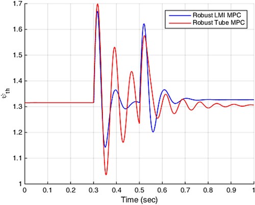
Figure 11. Plenum mass flow.
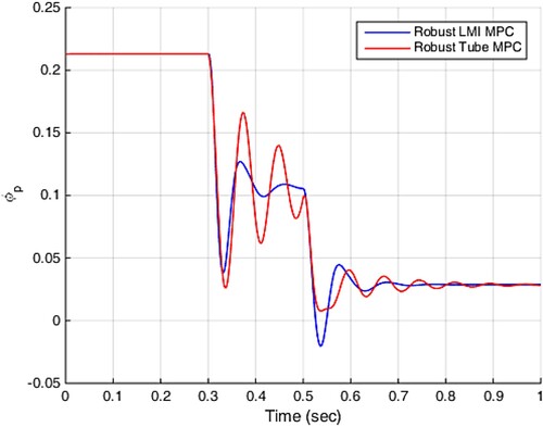
Figure 12. Control Signal.
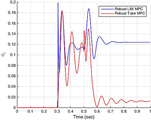
Carefully in Figure , it can be seen that small amplitude fluctuations in plenum pressure occur using the LMI MPC technique, and of course, more compression and faster achievement of a stable state is achieved in the proposed scheme, while less compression is obtained in the Tube-MPC technique, the amplitude of fluctuations is high, and of course, the plenum pressure reaches its final value in a longer period of time than the proposed method. It is also clear from Figure that the results obtained for plenum pressure are also valid for throttle pressure. More compression, less oscillation amplitude and less settling time are the advantages of the proposed LMI-MPC technique. The plenum flow shown in Figure also shows that less fluctuations and less settling time are advantages of the proposed LMI MPC technique and although the plenum flow is negative for a moment, it recovers rapidly and reaches its stable working point. The results obtained in Figure show that less fluctuations occur in the control signal obtained from the proposed LMI MPC technique and reach its final value faster. Also, the control signal is in the range between 0 and 1, i.e. the practical range of the CCV actuator is well observed and the obtained signal is executable and operational.
The time of performing control signal calculations in three methods: NMPC, Tube-MPC and LMI MPC is given in Table . The calculations are performed on a computer with Intel Core i5 processor, Intel UHD Graphics and 8 GB memory and it is obvious from Table that the time required to perform calculations in proposed approach is less than the other two techniques, and of course, it is very important in the case of online implementation and control.
Table 2. Calculation Time for NMPC, Tube-MPC and LMI-MPC Approaches.
5. Conclusion
In this paper, an optimal robust scheme is presented for controlling the surge instability of a constant speed centrifugal compressor system. The effects of uncertainty, input signal limitations, and system states constraints considered in the nonlinear model of compressor system including pipe effects, and a novel robust model predictive control scheme presented by using of linear matrix inequality scheme. Due to the simplicity of the proposed scheme structure, the time required to perform control signal calculations and optimization is less than other techniques and can be implemented online. The simulation results also indicated the capability of the LMI MPC technique to control surge, fast flow stabilization with insignificant fluctuations and obviously extra compression.
Disclosure statement
No potential conflict of interest was reported by the author(s).
References
- Margalida G, Joseph P, Roussette O, et al. Active flow control in an axial compressor for stability improvement: on the effect of flow control on stall inception. Exp Fluids. 2021;62(1):1–13. doi:10.1007/s00348-020-03104-4
- Nail B, Bekhiti B, Puig V. Internal stability improvement of a natural gas centrifugal compressor system based on a new optimal output feedback controller using block transformation and grey wolf optimizer. J Nat Gas Sci Eng. 2021;85:103697. doi:10.1016/j.jngse.2020.103697
- Yuan X, Zhang Z, Liang P, et al. A fusion TFDAN-Based framework for rotating machinery fault diagnosis under noisy labels. Applied Acoustics. 2024;219:109940. doi:10.1016/j.apacoust.2024.109940.
- Gravdahl JT, Egeland T. Compressor surge and rotating stall: Modeling and control Springer Science & Business Media; 2012.
- Greitzer EM. Surge and rotating stall in axial flow compressors—Part I: Theoretical compression system model; 1976.
- Greitzer EM. Surge and rotating stall in axial flow compressors—Part II: experimental results and comparison with theory; 1976.
- Sparks CR. On the transient interaction of centrifugal compressors and their piping systems; 1983.
- Brun K, Nored MG, Kurz R. Impact of piping impedance and acoustic characteristics on centrifugal compressor surge and operating range. J Eng Gas Turbines Power. 2015;137(3). doi:10.1115/1.4028464
- Arnulfi GL, Giannattasio P, Micheli D, et al. An innovative device for passive control of surge in industrial compression systems. J Turbomach 2001;123(3):473–482. doi:10.1115/1.1348021
- Yoon SY, Lin Z, Goyne C, et al. Control of compressor surge with active magnetic bearings. In: 49th IEEE Conference on Decision and Control (CDC). IEEE; 2010 Dec. p. 4323–4328.
- Imani H, Jahed-Motlagh MR, Salahshoor K, et al. Robust decentralizedmodel predictive control approach for a multi-compressor system surge instability including piping acoustic. Cogent Eng. 2018;5(1):1483811. doi:10.1080/23311916.2018.1483811.
- Taleb Ziabari M, Jahed-Motlagh MR, Salahshoor K, et al. Tube-MPC for a class of uncertain continuous nonlinear systems with application to surge problem. Kybernetika. 2017;53(4):679–693.
- Sheng H, Chen Q, Li J, et al. Robust adaptive backstepping active control of compressor surge based on wavelet neural network. Aerosp Sci Technol. 2020;106:106139. doi:10.1016/j.ast.2020.106139
- Sheng H, Huang W, Zhang T, et al. Robust adaptive fuzzy control of compressor surge using backstepping. Arab J Sci Eng. 2014;39(12):9301–9308. doi:10.1007/s13369-014-1448-1
- Yoon SY, Lin Z, Allaire PE. Experimental evaluation of a surge controller for an AMB supported compressor in the presence of piping acoustics. IEEE Trans Control Syst Technol. 2013;22(3):1215–1223. doi:10.1109/TCST.2013.2274729
- Imani H, Jahed-Motlagh MR, Salahshoor K, et al. Constrained nonlinear model predictive control for centrifugal compressor system surge including piping acoustic using closed coupled valve. Syst Sci Control Eng. 2017;5(1):342–349. doi:10.1080/21642583.2017.1367732
- Li T, Shi H, Bai X, et al. Early performance degradation of ceramic bearings by a twin-driven model. Mech Syst Signal Process. 2023;204:110826. doi:10.1016/j.ymssp.2023.110826.
- Liu L, Mei Q, Jia W. A flexible diesel spray model for advanced injection strategy. Fuel. 2022;314:122784. doi:10.1016/j.fuel.2021.122784
- Wang R, Gu Q, Lu S. FI-NPI: Exploring optimal control in parallel platform systems. Electronics. 2024;13(7):1168. doi:10.3390/electronics13071168
- Wang W, Liang J, Liu M, et al. Novel robust stability criteria for Lur’e systems with time-varying delay. Mathematics 2024;12(4):583. doi:10.3390/math12040583.
- Xie C, Marrani HI. Design of a robust LMI-based model predictive control method for surge instability in interconnected compressor systems in the presence of uncertainty and disturbance. Syst Sci Control Eng. 2021;9(1):358–368.
- Marrani HI, Fazeli S, Malekizade H, et al. Tube model predictive control for a class of nonlinear discrete-time systems. Cogent Eng. 2019;6(1):1629055.