
ABSTRACT
The effects of CO/H2/CH4 mixture compositions on the reactivity are investigated based on weak flame responses in a micro flow reactor with a controlled temperature profile (MFR). The ratios of H2 and CH4 are varied widely at a constant fraction of CO and the effects of variations in the compositions on the reactivity of the stoichiometric CO/H2/CH4 mixtures are evaluated both experimentally and computationally at atmospheric pressure. The results show that a weak flame is stabilized at the higher temperature region in MFR as the CH4 mole fraction increases, which indicates that the reactivity of the CO/H2/CH4 mixtures decreases with the increase of the CH4 mole fraction. Ignition delay times of the CO/H2/CH4 mixtures are also computed using a detailed chemical reaction model. The computed ignition delay times of the CO/H2/CH4 mixtures largely increase as the CH4 mole fraction increases, which is consistent with the variation in the reactivity shown by weak flames in MFR. Rate-of-production analyses using a detailed chemical reaction model show that the OH radical consumption by CH4 increases and that by H2 decreases as the CH4 fraction increases. Consequently, the production rate of CH3 radicals, which are less reactive than H radicals, increases and the production rate of H radicals decreases. This can suppress the OH formation from H radicals. Therefore, the primary factor of the significant reduction of the reactivity of the CO/H2/CH4 mixtures seems to be the increase of the OH radical consumption by CH4 and the CH3 radical production due to the increase in the CH4 fraction.
Introduction
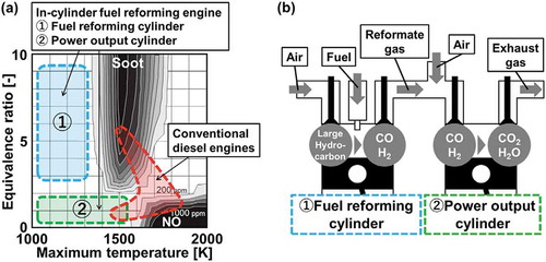
Diesel engines are one of the most commonly used powertrains in transport sectors since they are highly efficient and durable. Recently, however, soot and NOx emissions from large transport machines such as trucks and ships are being strongly restricted due to severe environmental pollutions. , called ɸ-T diagram (Kamimoto and Bae Citation1988), shows the correlation between soot/NOx formation regime and corresponding equivalence ratio/maximum temperature (Akihama Citation2014) conditions. As shown in , the combustion condition of diesel engines covers a large part of the soot and NOx formation regime. In order to reduce the pollutant emissions, installations of exhaust treatment systems using catalysts or particle filters (Guan et al. Citation2015) have been considered. However, installing these systems requires large spaces and high costs, which can present barriers to satisfy future strict regulations on the emissions. To resolve this difficulty, an engine involving in-cylinder fuel reformation is under development (Asai et al. Citation2018). A conceptual image of an in-cylinder fuel reforming engine is presented in . In this engine, some cylinders are used for fuel reforming and the rest are used for power output. In a reforming cylinder, a reformate gas, which mainly includes CO and H2, is produced from partial oxidations of fuel/air mixtures at an extremely fuel-rich condition through piston compression-expansion strokes. The produced reformate gas is then introduced into an output cylinder with air. Subsequently, combustion of the reformate gas/air mixtures takes place near stoichiometry to extract the power output. In fuel reforming cylinders, the flame temperature is expected to be lower because of extremely fuel-rich conditions, which mitigates soot formation (regime ① in ). In a power output cylinder, even near stoichiometry, a lower flame temperature condition can be realized because of the dilution with N2, CO2, and H2O included in the reformate gases (regime② in ). Therefore, in-cylinder fuel reforming engines can realize low soot and NOx emissions by controlling combustion conditions for each cylinder without any exhaust gas treatment systems.
Figure 1. (a) Combustion conditions of conventional diesel engines and in-cylinder fuel reforming engines described onɸ-T diagram (Kamimoto, Citation1988; Akihama, Citation2014) and (b) A conceptual scheme of in-cylinder fuel reforming engine
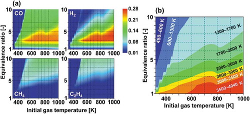
In the in-cylinder fuel reforming engine, however, the compositions of the reformate products can vary widely depending on the reforming conditions. This has been reported in many practical applications such as biomass and coal reforming in stationary power plants (Chacartegui et al. Citation2011; Göransson et al. Citation2011; Tian et al. Citation2017). In an earlier work (Murakami et al. Citation2017), we demonstrated fuel reforming of a large hydrocarbon in an engine cylinder using zero-dimensional engine simulations. This computation simulated one cycle of piston compression-expansion strokes in an engine cylinder at adiabatic condition. Equivalence ratio and initial gas temperature of fuel/air mixtures were varied and their effects on the compositions of reformate products were investigated. shows the estimated mole fractions of representative reformate products. According to the results, CO and H2 are the major products for the lower equivalence ratio conditions, whereas other species, especially small hydrocarbons such as CH4, C2H4 are producible for higher equivalence ratio conditions where the maximum gas temperature during the reforming process is around 1300–1700 K, as shown in . This tendency was also confirmed from experiments with a lab-scale diesel engine (Asai et al. Citation2018). These variations in compositions of reformate products can considerably change the reactivity of mixtures, thereby exerting marked effects on the design and the development of engines. Therefore, the impacts of small hydrocarbons on the reactivity of reformate gases have to be further investigated.
Figure 2. (a) Computed mole fractions of CO, H2, CH4 and C2H4 produced in fuel reforming of n-tridecane/air mixtures after one cycle of piston compression-expansion strokes in an engine cylinder at adiabatic condition (Murakami, Citation2017) and (b) Computed maximum gas temperatures during the fuel reforming process
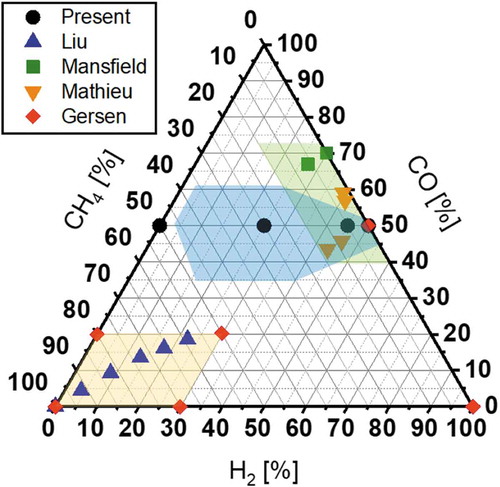
However, experimental investigations on the reactivity of reformate gases including small hydrocarbons are still quite limited while many studies have assessed the reactivity of pure CO/H2 mixtures (Dryer and Chaos Citation2008; Frassoldati, Faravelli, Ranzi Citation2007; Nakamura et al. Citation2016; Natarajan, Lieuwen, Seitzman Citation2007; Petersen et al. Citation2007; Walton et al. Citation2007). In order to compare target mixture conditions investigated in the present study and earlier works considering the reactivity of CO/H2 mixtures with small hydrocarbons (Gersen, Darmeveil, Levinsky Citation2012; Liu et al. Citation2018; Mansfield and Wooldridge Citation2015; Mathieu et al. Citation2015; Mathieu, Kopp, Petersen Citation2013), a CO-H2-CH4 ternary diagram is introduced (). CH4 is selected as a representative small hydrocarbon because it is the simplest hydrocarbon and the most likely to be included in reformate products besides CO and H2. For each plot in , the mole fractions of CO, H2 and CH4 are extracted from the literatures (Gersen, Darmeveil, Levinsky Citation2012; Liu et al. Citation2018; Mansfield and Wooldridge Citation2015; Mathieu et al. Citation2015; Mathieu, Kopp, Petersen Citation2013) and normalized. As might be readily apparent, most cases are located on several specific regions in the chart. The mixture conditions around CO/H2 = 50/50 (the green shaded region) are intended for mixtures from coal and biomass reforming (Mansfield and Wooldridge Citation2015; Mathieu et al. Citation2015; Mathieu, Kopp, Petersen Citation2013). The conditions including a large amount of CH4 (the yellow shaded region) are considered for the utilization of synthetic natural gas (Gersen, Darmeveil, Levinsky Citation2012) and the condition for dual fuel of natural gas and reformate gases (Liu et al. Citation2018). On the other hand, the estimated mixture conditions for the in-cylinder fuel reforming engine (Murakami et al. Citation2017) are portrayed as the blue shaded region, where few experimental data exist. These indicate that target compositions can widely differ depending on applications and few investigations have specifically examined mixtures including CO, H2, and CH4 simultaneously.
Figure 3. A ternary diagram indicating mixture conditions experimentally investigated for the reactivity of CO2/CH4 mixtures in the present and earlier studies (Gersen, Citation2012; Mathieu, Citation2013, Citation2015; Mansfield, Citation2015; Liu, Citation2018)
Motivated by these facts, this study examines the reactivity of CO/H2/CH4 mixtures expected to be produced in in-cylinder fuel reforming engines. The evaluation of the reactivity of mixtures is performed based on weak flame responses in a micro flow reactor with a controlled temperature profile (MFR) (Maruta et al. Citation2005). MFR comprises a quartz tube with an inner diameter smaller than a conventional quenching diameter and an external heat source. Along the inner wall of the quartz tube, a stationary temperature profile is formed by an external heat source. When the flow velocity of test mixtures is extremely slow (a few centimeters per second) in MFR, weak flames can be observed as a steady phenomenon. A theoretical analysis showed that weak flames in MFR correspond to a flame response on the ignition branch of the Fendell curve (Minaev, Maruta, Fursenko Citation2007). At the conditions where weak flames can be observed, the gas phase temperature is strongly governed by the given wall temperature because of the significant heat transfer in a narrow channel and a small chemical input. Therefore, a rapid temperature increase due to the heat release is suppressed and temperature difference between gas and wall is extremely small even at the reaction zone (typically less than 10 K). On this basis, the wall temperature at the weak flame position is considered to be a representative temperature of corresponding oxidation. Thus, fuel reactivities have been measured by observing weak flame responses. The capabilities of MFR to investigate the reactivity of a given mixture have been demonstrated in past studies (Hori et al. Citation2012; Kikui et al. Citation2016; Maruta et al. Citation2005; Nakamura and Shindo Citation2019; Oshibe et al. Citation2010; Takahashi et al. Citation2019; Tsuboi, Yokomori, Maruta Citation2009; Yamamoto et al. Citation2011). Moreover, MFR is capable of examining extremely low-reactivity mixtures such as pure CO or highly diluted mixtures due to the existence of the external heat source and the long residence time, which is a preferable feature especially when mixtures have wide range of reactivity (Nakamura et al. Citation2016).
In the present study, the effects of composition changes in CO/H2/CH4 mixtures on the reactivity are evaluated based on weak flame responses in MFR. Specifically, the ratios of H2 and CH4 are varied widely at a constant fraction of CO. Details of the mixture conditions investigated in this study are discussed later. Experimental measurements are compared to computational predictions using several detailed chemical reaction models. A further chemical reaction analysis is then conducted to investigate chemical mechanism behind a trend observed in the experiments.
Experimental and computational methods
Micro flow reactor with a controlled temperature profile (MFR)
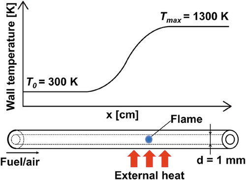
The experiment setup is depicted in . A quartz tube (inner diameter: 1 mm, outer diameter: 3 mm) is used as the reactor channel. Note that past studies confirmed that the influence of the chemical reaction on the wall surface is negligible (Kizaki et al. Citation2015; Oshibe et al. Citation2010; Saiki and Suzuki Citation2013). The reactor is arranged in the horizontal direction. A H2/air flat-flame burner is settled under the reactor to form a stationary temperature profile with the maximum temperature of 1300 K along the reactor wall. The wall temperature profile is measured using a K-type thermocouple inserted from the downstream side of the reactor.
Figure 4. Schematic of a micro flow reactor with a controlled temperature profile
Flames are observed using a digital still camera (Nikon D800) with a CH bandpass filter (Optical Coating Japan, DIF-BP, 431.4 nm transparent wavelength, 6.5 nm half bandwidth) to exclude thermal radiation from the heated reactor wall. Flame pictures are taken after at least 15 mins so that the mixture flow is stabilized. The exposure time is fixed as 3 mins because the chemiluminescence from weak flames is quite dim. A flame location in the experiment is defined as the location of the peak of the luminosity profile of a flame image. The brightness profile along the flow direction is generated by calculating the average brightness value of vertical pixels. Each experiment is conducted at atmospheric pressure. Since the test mixtures in the present study includes CO, brass material is used for the parts which CO is expected to contact for the purpose of preventing the formation of CO complex, which reportedly affects the combustion characteristics (Williams and Shaddix Citation2007).
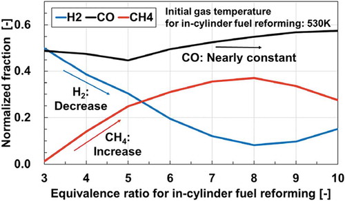
As mentioned earlier, the present study considers CO, H2 and CH4 as fuel components. In order to determine fractions of fuel components, a trend in the fractions of these three components obtained from the computation for in-cylinder fuel reforming is referred (Murakami et al. Citation2017). We focused on the fractions of these components at the initial temperature of 530 K for in-cylinder fuel reforming, which is a practical operating temperature of the engine. The computed mole fractions of CO, H2 and CH4 at the initial reforming temperature of 530 K are extracted and normalized. The normalized fractions of CO, H2 and CH4 are then plotted along the equivalence ratio conditions for the fuel reforming (). According to , the H2 fraction is replaced with the CH4 fraction at an almost identical proportion, although the CO mole fraction keeps nearly constant (around 50%) over the almost entire range of the equivalence ratio considered. This trend is visible over various initial gas temperature conditions. Consequently, simplified compositions of test mixtures are determined based on the following rule: the CO fraction is constant (50%) and the H2 fraction is replaced with the CH4 fraction every 5%. The mole fractions of the mixtures are shown in . In the experiment, four conditions (CO/H2/CH4 = 50/50/0, 50/45/5, 50/25/25, 50/0/50) are examined (the shaded conditions in ). Air is used as an oxidizer and the mixture flow velocity is set to 3 cm/s. All experiments are conducted at atmospheric pressure and a stoichiometric condition.
Table 1. Mole fractions of mixture components investigated in the present study. Shaded conditions indicate the mixtures considered in both experiments and computations. Non-shaded conditions indicate the mixtures considered only in computations
Figure 5. Normalized fractions of CO, H2 and CH4 plotted along equivalence ratio conditions for in-cylinder fuel reforming at 530 K (the initial gas temperature for in-cylinder fuel reforming)
Computational methods
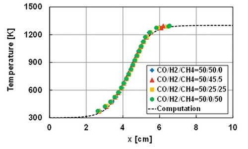
At the low flow velocity conditions such that weak flames can be observed in MFR, the flow in a reactor can be considered as a one-dimensional steady-state reactive diffusive flow without a boundary layer. Such a reactive flow condition can be simulated by adding a heat convection term between the reactor wall and the gas phase to the energy equation in the governing equations of the one-dimensional freely propagating premixed flame. On this basis, the modified PREMIX package in ANSYS Chemkin-Pro v19.0 (ANSYS, Citation2019) is used to conduct one-dimensional steady computations (Maruta et al. Citation2005). The computational domain is 10 cm long and an estimated wall temperature profile of 300–1300 K shown in is given in the computation. A flame location in the computation is defined as the location of the peak of [CO]*[O] profile based on the literature reporting the chemiluminescence from various syngas mixtures is derived from CO2* yielded from CO + O + M = CO2* + M (Kopp et al. Citation2012; Kopp, Mathieu, Petersen Citation2014). All mixture conditions in are considered in the computation. Four detailed chemical reaction models are employed: USC mech ver. II (Wang et al. Citation2007), San Diego mechanism (University of California at San Diego Citation2016), AramcoMech3.0 (Zhou et al. Citation2018), and HPmech (Shen et al. Citation2015; Zhao et al. Citation2017).
Figure 6. The measured wall temperatures of the reactor and the estimated wall temperature profile used in the computation
In this study, ignition delay times are also assessed in the computation as a different indicator of the mixture reactivity. The computation is conducted using a zero-dimensional homogeneous reactor model in the AURORA package of ANSYS Chemkin-Pro v19.0 (ANSYS® Citation2019). The mixture conditions considered are the same as the MFR computations. HPmech is used as a detailed chemical reaction model. The computation is performed for atmospheric pressure and stoichiometry.
Results and discussion
Weak flame responses in MFR
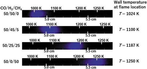
Weak flame pictures of four CO/H2/CH4 mixtures in the experiment are presented in . The flame location obviously shifts greatly to the higher temperature region of the reactor as the H2 fraction decreases and the CH4 fraction increases, which indicates that the reactivity of the mixture decreases along the variation in the compositions. The difference in the wall temperature at a flame location is approximately 226 K between the case of CO/H2/CH4 = 50/50/0 and 50/0/50. According to an earlier study considering the research octane number (RON) effect on the weak flame location in the MFR (Hori et al. Citation2012), the difference in the wall temperature is approximately 40 K between RON = 0 and 100. Based on this fact, it must be emphasized that the variation in the reactivity investigated in this study is extremely large. Moreover, the shift size seems greater in the case with the small CH4 fraction (CH4 = 0% and 5%, ΔT = 76 K) compared to the cases of the larger CH4 fractions (CH4 = 25% and 50%, ΔT = 63 K). This point will be referred in the later section.
Figure 7. Weak flame images of CO/H2/CH4 = 50/50/0, 50/45/5, 50/25/25 and 50/0/50 obtained in the experiment
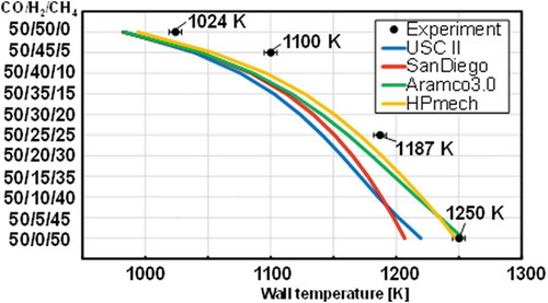
shows the comparison between the experimental measurements and computed flame locations. The uncertainty of flame locations is less than 5 K. In the computational results, the weak flame position shifted considerably to the higher temperature region as the H2 fraction decreases and the CH4 fraction increases. This trend is consistent with the experimental results. A larger shift of the flame locations is also observed in the computation for the cases with the small CH4 fractions. Although the experimental and computational weak flame positions show qualitative agreement for all conditions, weak flames in the computation still tend to be located in the upstream side compared to the experimental flame locations. A further investigation must be conducted to assess the quantitative difference. Among four chemical reaction models used in this study, HPmech showed the best agreement with the experimental weak flame positions in most mixture conditions. Hence, further analyses of chemical reactions have been conducted based on results from HPmech.
Figure 8. Comparison of weak flame locations of the stoichiometric CO/H2/CH4 mixtures between the experimental measurements (Black plots) and the computational predictions (Colored lines). The uncertainty of the wall temperature at a flame location is less than 5 K
In order to show the correlation between the mixture reactivity indicated by weak flames and ignition delay times, the computed ignition delay time of the CO/H2/CH4 mixtures is presented in . One apparent observation is that the ignition delay time increases as the H2 fraction decreases and the CH4 fraction increases in the temperature range over the entire range considered. The trend is consistent with that indicated by the weak flames in the MFR experiment. It should be noted that the changes in the ignition delay time due to the variation in the mixture compositions are significant. The difference in ignition delay times between CO/H2/CH4 = 50/50/0 and 50/0/50 is quite large (approx. a factor of 2000 at T = 1000 K). In order to experimentally measure ignition delay times with such a wide variation, both a shock tube and a rapid compression machine are generally required. Therefore, it is worth emphasizing that this study demonstrated the capability of MFR to evaluate mixtures with widely varied reactivities in a simple and well-defined configuration.
Figure 9. Computed ignition delay times of stoichiometric CO/H2/CH4/air mixtures at atmospheric pressure and initial temperatures of 800-1600 K by HPmech
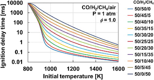
Another observation can be made for the cases with large amounts of H2 in the mixtures. In a low-temperature region (below 900 K), the ignition delay time is mostly similar regardless of mixture compositions. However, once the temperature increases to over 900 K, the ignition delay time decreases rapidly in the cases of CO/H2/CH4 = 50/50/0, 50/45/5, and 50/40/10. This behavior is attributable to the shift in the dominant reaction path of H2-O2 system (Kéromnès et al. Citation2013). Under the low-temperature condition, the oxidation process of H2 is governed by H + O2 (+M) = HO2 (+M). HO2 radicals produce H2O2 through H2 + HO2 = H2O2 + H. Finally, OH radicals are produced by the decomposition of H2O2. In the high-temperature condition, OH radicals are produced mainly through H + O2 = O + OH. This change in dominant reactions is apparent in the second explosion limit (Mueller et al. Citation1999; Zheng and Law Citation2004). The same trend was identified in an earlier study of CO/H2 mixtures with MFR to investigate the effects of inert mixtures ([M]) on the syngas reactivity (Nakamura et al. Citation2016). As the CH4 fraction increases, the trend disappears because the dominant reaction is suppressed by reactions involving CH4 and its related species. Since this study is originally motivated by the engine development, investigating the interactions between CH4 and the H2-O2 system at high-pressure conditions must be interesting as a next subject.
Chemical reaction analysis
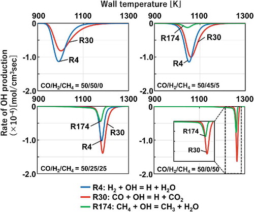
In general, ignition phenomena proceed with exponential increases of radicals. Especially, OH radical is a crucially important species for the initiation of fuel oxidations. Therefore, rate-of-production analysis of the OH consumption is conducted to investigate the effects of the mixture compositions on the variation in the reactivity of the CO/H2/CH4 mixtures. portrays the results of the rate-of-production of OH radicals by fuel components computed with HPmech. In the case of CO/H2/CH4 = 50/50/0, OH radicals are mainly consumed by H2 and CO through R4: H2 + OH = H + H2O and R30: CO + OH = H + CO2. However, once CH4 is included as a fuel component (CO/H2/CH4 = 50/45/5, 50/25/25, 50/0/50), CH4 starts consuming OH radicals through R174: CH4 + OH = CH3 + H2O and competes with CO and H2 for OH radicals. Here is an important difference in the products from these reactions. Through R4 and R30, H2 and CO consume OH radicals and produce H radicals as a product while CH4 consume OH radicals through R174 and produces CH3 radicals. As mentioned in the previous section, H radicals lead a chain-branching reaction and play an important role in the OH radical formation. Produced OH radicals promote the further destruction of fuel components. In contrast, CH3 radicals are less reactive compared to H radicals. Since the rate of CH3 radical production increases and the rate of H radical production decreases as the CH4 fraction increases, the OH formation from H radicals can be suppressed. This inhibitory effect of CH4 results in the large decrease in the reactivity of the CO/H2/CH4 mixtures. Although the subsequent recombination reaction of a CH3 radical and a H radical, CH3 + H (+M) = CH4 (+M), can also have a great impact on inhibiting the reactivity of the mixtures as reported in past studies (Mathieu et al. Citation2015; Mathieu, Kopp, Petersen Citation2013), additional diagnostics have to be made to reason these effects in the MFR system. Thus, the competition of OH radicals by CO, H2, and CH4 and the larger production of CH3 radicals appear to be the primary factor in the large decrease in the reactivity.
Figure 10. Rate of OH production for the cases of CO/H2/CH4 = 50/50/0, 50/45/5, 50/25/25 and 50/0/50. (Negative value indicates consumption.)
As mentioned in the earlier section, the shift size of flame locations becomes smaller as the CH4 fraction increases. In order to explain the differences in the shift size between flame locations, the temperature profile in the MFR system should be considered. As the CH4 fraction increases, the mixture reactivity decreases, and the flame shifts to the higher temperature regime where a reaction can much easier to proceed. Therefore, the shift of flame locations becomes smaller in the higher temperature region compared to that in the lower temperature region because the inhibitory effects of CH4 become less emphasized due to the nature of the unique temperature profile of the MFR system.
Conclusions
The reactivity of stoichiometric CO/H2/CH4/air mixtures at various compositions were examined by weak flame responses in MFR. Both experimental and computational results showed that weak flame locations of the CO/H2/CH4 mixtures shifted greatly to the higher temperature region as the H2 fraction decreases and the CH4 fraction increases, which interprets the reactivity of the CO/H2/CH4/air mixtures decreases considerably. Computational ignition delay times of the same mixtures at atmospheric pressure also indicated that the reactivity of those mixtures largely decreases as CH4 fraction increases. According to the rate-of-production analysis for OH radicals, it was demonstrated that OH radicals are consumed mainly by fuel components, CO, H2, and CH4 in all mixture compositions. For the CO/H2 mixtures, OH radicals are mainly consumed by CO and H2. Subsequently, H radicals are produced through R4: H2 + OH = H + H2O and R30: CO + OH = H + CO2. However, once CH4 is included in the CO/H2 mixtures, CH4 starts consuming OH radicals through R174: CH4 + OH = CH3 + H2O and produces CH3 radicals, which are less reactive species. The consumption rate of OH radicals by CH4 became larger as the CH4 fraction increased. This can suppress the OH formation from H radicals. Therefore, primary factor of the significant decrease in the reactivity of the CO/H2/CH4 mixtures seems to be the increase of the OH consumption by CH4 and the CH3 radical production due to the increase of the CH4 fraction.
Additional information
Funding
References
- Akihama, K. 2014. A point of contact between a φ-T map and engine combustion concepts. J. Combust. Soc. Japan 56:291.
- ANSYS®. 2019. Chemkin-Pro, Release 19.0.
- Asai, G., Y. Watanabe, S. Ishiguro, G. Shibata, H. Ogawa, Y. Kobashi, and T. Suzuki. 2018. Diesel fuel reformation by piston compression of rich mixture. Trans. Soc. Automot. Eng. Japan 49:24.
- Chacartegui, R., M. Torres, D. Sánchez, F. Jiménez, A. Muñoz, and T. Sánchez. 2011. Analysis of main gaseous emissions of heavy duty gas turbines burning several syngas fuels. Fuel Process. Technol. 92:213. doi:10.1016/j.fuproc.2010.03.014.
- Dryer, F. L., and M. Chaos. 2008. Ignition of syngas/air and hydrogen/air mixtures at low temperatures and high pressures: Experimental data interpretation and kinetic modeling implications. Combust. Flame 152:293. doi:10.1016/j.combustflame.2007.08.005.
- Frassoldati, A., T. Faravelli, and E. Ranzi. 2007. The ignition, combustion and flame structure of carbon monoxide/hydrogen mixtures. Note 1: Detailed kinetic modeling of syngas combustion also in presence of nitrogen compounds. Int. J. Hydrogen Energy 32:3471. doi:10.1016/j.ijhydene.2007.01.011.
- Gersen, S., H. Darmeveil, and H. Levinsky. 2012. The effects of CO addition on the autoignition of H2, CH4 and CH4/H2 fuels at high pressure in an RCM. Combust. Flame 159:3472.
- Göransson, K., U. Söderlind, J. He, and W. Zhang. 2011. Review of syngas production via biomass DFBGs. Renew. Sustain. Energy Rev. 15:482. doi:10.1016/j.rser.2010.09.032.
- Guan, B., R. Zhan, H. Lin, and Z. Huang. 2015. Review of the state-of-the-art of exhaust particulate filter technology in internal combustion engines. J. Environ. Manage. 154:225. doi:10.1016/j.jenvman.2015.02.027.
- Hori, M., A. Yamamoto, H. Nakamura, T. Tezuka, S. Hasegawa, and K. Maruta. 2012. Study on octane number dependence of PRF/air weak flames at 1–5 atm in a micro flow reactor with a controlled temperature profile. Combust. Flame 159:959. doi:10.1016/j.combustflame.2011.09.020.
- Kamimoto, T., and M. H. Bae. 1988. High combustion temperature for the reduction of particulate in diesel engines. SAE Technical Paper. 880423.
- Kéromnès, A., W. K. Metcalfe, K. A. Heufer, N. Donohoe, A. K. Das, C. J. Sung, J. Herzler, C. Naumann, P. Griebel, O. Mathieu, et al. 2013. An experimental and detailed chemical kinetic modeling study of hydrogen and syngas mixture oxidation at elevated pressures. Combust. Flame 160:995. doi:10.1016/j.combustflame.2013.01.001.
- Kikui, S., H. Nakamura, T. Tezuka, S. Hasegawa, and K. Maruta. 2016. Study on combustion and ignition characteristics of ethylene, propylene, 1-butene and 1-pentene in a micro flow reactor with a controlled temperature profile. Combust. Flame 163:209.
- Kizaki, Y., H. Nakamura, T. Tezuka, S. Hasegawa, and K. Maruta. 2015. Effect of radical quenching on CH4/air flames in a micro flow reactor with a controlled temperature profile. Proc. Combust. Inst. 35:3389. doi:10.1016/j.proci.2014.07.030.
- Kopp, M., M. Brower, O. Mathieu, E. Petersen, and F. Güthe. 2012. CO2* chemiluminescence study at low and elevated pressures. Appl. Phys. B Lasers Opt. 107:529. doi:10.1007/s00340-012-5051-4.
- Kopp, M. M., O. Mathieu, and E. L. Petersen. 2014. Rate determination of the CO2* chemiluminescence reaction CO + O + M ⇄ CO2* + M. Int. J. Chem. Kinet. 47:50. doi:10.1002/kin.20892.
- Liu, C., H. Song, P. Zhang, Z. Wang, M. S. Wooldridge, X. He, and G. Suo. 2018. A rapid compression machine study of autoignition, spark-ignition and flame propagation characteristics of H2/CH4/CO/air mixtures. Combust. Flame 188:150. doi:10.1016/j.combustflame.2017.09.031.
- Mansfield, A. B., and M. S. Wooldridge. 2015. The effect of impurities on syngas combustion. Combust. Flame 162:2286. doi:10.1016/j.combustflame.2015.01.026.
- Maruta, K., T. Kataoka, N. Kim, S. Minaev, and R. Fursenko. 2005. Characteristics of combustion in a narrow channel with a temperature gradient. Proc. Combust. Inst. 30:2429. doi:10.1016/j.proci.2004.08.245.
- Mathieu, O., J. Hargis, A. Camou, C. Mulvihill, and E. L. Petersen. 2015. Ignition delay time measurements behind reflected shock-waves for a representative coal-derived syngas with and without NH3 and H2S impurities. Proc. Combust. Inst. 35:3143. doi:10.1016/j.proci.2014.06.062.
- Mathieu, O., M. M. Kopp, and E. L. Petersen. 2013. Shock-tube study of the ignition of multi-component syngas mixtures with and without ammonia impurities. Proc. Combust. Inst. 34:3211. doi:10.1016/j.proci.2012.05.008.
- Minaev, S., K. Maruta, and R. Fursenko. 2007. Nonlinear dynamics of flame in a narrow channel with a temperature gradient. Combust. Theory Model. 11:187. doi:10.1080/13647830600649364.
- Mueller, M. A., T. J. Kim, R. A. Yetter, and F. L. Dryer. 1999. Flow reactor studies and kinetic modeling of the H2/O2 reaction. Int. J. Chem. Kinet. 31:113. doi:10.1002/(SICI)1097-4601(1999)31:2<113:AID-KIN5>3.0.CO;2-0.
- Murakami, Y., H. Nakamura, T. Tezuka, S. Hasegawa, G. Asai, and K. Maruta, 2017. Properties of in-cylinder fuel reformation and ignition characteristics of CO/H2/CH4 mixtures. In: 11th Asia-Pacific Conference on Combustion,Sydney, Australia.
- Nakamura, H., H. Takahashi, T. Tezuka, S. Hasegawa, K. Maruta, and K. Abe. 2016. Effects of CO-to-H2 ratio and diluents on ignition properties of syngas examined by weak flames in a micro flow reactor with a controlled temperature profile. Combust. Flame 172:94.
- Nakamura, H., and M. Shindo. 2019. Effects of radiation heat loss on laminar premixed ammonia/air flames. Proc. Combust. Inst. 37:1741. doi:10.1016/j.proci.2018.06.138.
- Natarajan, J., T. Lieuwen, and J. Seitzman. 2007. Laminar flame speeds of H2/CO mixtures: Effect of CO2 dilution, preheat temperature, and pressure. Combust. Flame 151:104. doi:10.1016/j.combustflame.2007.05.003.
- Oshibe, H., H. Nakamura, T. Tezuka, S. Hasegawa, and K. Maruta. 2010. Stabilized three-stage oxidation of DME/air mixture in a micro flow reactor with a controlled temperature profile 1300 K. Combust. Flame 157:1572. doi:10.1016/j.combustflame.2010.03.004.
- Petersen, E. L., D. M. Kalitan, A. B. Barrett, S. C. Reehal, J. D. Mertens, D. J. Beerer, R. L. Hack, and V. G. McDonell. 2007. New syngas/air ignition data at lower temperature and elevated pressure and comparison to current kinetics models. Combust. Flame 149:244. doi:10.1016/j.combustflame.2006.12.007.
- Saiki, Y., and Y. Suzuki. 2013. Effect of wall surface reaction on a methane-air premixed flame in narrow channels with different wall materials. Proc. Combust. Inst. 34:3395. doi:10.1016/j.proci.2012.06.095.
- San Diego Mechanism web page, University of California at San Diego. 2016. Chemical-kinetic mechanisms for combustion applications. http://combustion.ucsd.edu
- Shen, X., X. Yang, J. Santner, J. Sun, and Y. Ju. 2015. Experimental and kinetic studies of acetylene flames at elevated pressures. Proc. Combust. Inst. 35:721. doi:10.1016/j.proci.2014.05.106.
- Takahashi, S., H. Nakamura, T. Tezuka, S. Hasegawa, and K. Maruta. 2019. Multi-stage oxidation of a CH2F2/air mixture examined by weak flames in a micro flow reactor with a controlled temperature profile. Combust. Flame 201:140. doi:10.1016/j.combustflame.2018.12.014.
- Tian, T., Q. Li, R. He, Z. Tan, and Y. Zhang. 2017. Effects of biochemical composition on hydrogen production by biomass gasification. Int. J. Hydrogen Energy 42:19723. doi:10.1016/j.ijhydene.2017.06.174.
- Tsuboi, Y., T. Yokomori, and K. Maruta. 2009. Lower limit of weak flame in a heated channel. Proc. Combust. Inst. 32:3075. doi:10.1016/j.proci.2008.06.151.
- Walton, S. M., X. He, B. T. Zigler, and M. S. Wooldridge. 2007. An experimental investigation of the ignition properties of hydrogen and carbon monoxide mixtures for syngas turbine applications. Proc. Combust. Inst. 31:3147. doi:10.1016/j.proci.2006.08.059.
- Wang, H., You, X., Joshi, A. V., Davis, S. G., Laskin, A., Egolfopoulos, F. and Law, C. K. 2007. USC mech version II. High-Temperature Combustion Reaction Model of H2/CO/C1-C4 Compounds. http://ignis.usc.edu/USC_Mech_II.htm
- Williams, T. C., and C. R. Shaddix. 2007. Contamination of carbon monoxide with metal carbonyls: Implications for combustion research. Combust. Sci. Technol. 179:1225. doi:10.1080/00102200601057279.
- Yamamoto, A., H. Oshibe, H. Nakamura, T. Tezuka, S. Hasegawa, and K. Maruta. 2011. Stabilized three-stage oxidation of gaseous n -heptane/air mixture in a micro flow reactor with a controlled temperature profile. Proc. Combust. Inst. 33:3259. doi:10.1016/j.proci.2010.05.004.
- Zhao, H., J. Fu, F. M. Haas, and Y. Ju. 2017. Effect of prompt dissociation of formyl radical on 1,3,5-trioxane and CH2O laminar flame speeds with CO2 dilution at elevated pressure. Combust. Flame 183:253. doi:10.1016/j.combustflame.2017.05.005.
- Zheng, X., and C. Law. 2004. Ignition of premixed hydrogen/air by heated counterflow under reduced and elevated pressures. Combust. Flame 136:168. doi:10.1016/j.combustflame.2003.09.016.
- Zhou, C.-W., Y. Li, U. Burke, C. Banyon, K. P. Somers, S. Ding, S. Khan, J. W. Hargis, T. Sikes, O. Mathieu, et al. 2018. An experimental and chemical kinetic modeling study of 1,3-butadiene combustion: Ignition delay time and laminar flame speed measurements. Combust. Flame 197:423. doi:10.1016/j.combustflame.2018.08.006.