
 ?Mathematical formulae have been encoded as MathML and are displayed in this HTML version using MathJax in order to improve their display. Uncheck the box to turn MathJax off. This feature requires Javascript. Click on a formula to zoom.
ABSTRACT
The flame–turbulence interaction and statistical behavior of the surface density function (SDF; i.e. magnitude of the reaction progress variable gradient) in the vicinity of the wall for a stoichiometric methane-air flame are investigated using a three-dimensional direct numerical simulation of a turbulent premixed V-flame interacting with an isothermal inert wall in a fully developed turbulent channel flow at a friction Reynolds number . The results show that the mean SDF significantly decreases in the viscous sublayer in comparison to the corresponding values for the same reaction progress variable in the unstretched laminar flame. Moreover, the mean values of SDF for a given value of reaction progress variable decrease in the downstream direction with the progress of flame quenching in all zones of turbulent boundary layer. The effective normal strain rate
(
), which acts to reduce the SDF as it increases, is much higher in the viscous sublayer than in the other layers. In the viscous sublayer, the contribution of the gradient of displacement speed in the flame-normal direction (
) to
has been shown to dominate the fluid-dynamic normal strain rate (
). This tendency is qualitatively similar to the previous findings for a V-flame interacting with an isothermal inert wall at
. However, the maximum mean value of
at
is approximately twice of that at
, which causes a sharper drop in the SDF in the viscous sublayer at higher
.
Introduction
The size of modern combustors in automobile and aeroengines has decreased over time to make them compact, light, and compatible with hybrid electric propulsion systems. As a result of size reduction, the flame is more likely to interact with the chamber wall. Therefore, the fundamental physical understanding of the flame–wall interaction (FWI) plays a pivotal role in the design of modern combustors. FWI under turbulent conditions is driven by the intermittent passage of cold unburned and hot burned gases close to the wall. The heat flux at the wall is determined by contact with hot and cold gases and the proximity of the flame front to the wall. In most practical combustion devices, the typical burned gas temperature remains about 1200–800 K, whereas the wall temperature of the combustor is often kept in the range of 800–1000 K because of cooling so that structural integrity is maintained. Thus, a temperature change of the order of 400–800 K occurs within a thin layer of the order of 1.0 mm from the wall, giving rise to large magnitudes of heat flux (Poinsot and Veynante Citation2005). FWI analysis using experimental techniques is challenging because of the spatial resolution requirements. Moreover, the transient effects associated with FWI (e.g., high wall flux for a short duration followed by reduced values of heat flux for a relatively long interval) make experimental characterization of the underlying combustion process extremely difficult. The flame usually quenches close to the wall (a typical distance of the order of 1.0 µm), as the reduced wall temperature often does not allow for high-temperature chemical reactions to be sustained. Thus, the near-wall region must be resolved sufficiently to obtain fundamental physical insights into FWI. This resolution can be achieved using direct numerical simulations (DNS), where all relevant length and time scales of the turbulence and combustion processes are resolved without any physical approximation. In the last two decades, the DNS of reacting flows has led to significant advancements in the physical understanding and modeling of turbulent combustion modeling (Domingo and Vervisch Citation2022). However, to date, most combustion DNS studies have been carried out in canonical configurations in the absence of no-slip wall boundary conditions (Domingo and Vervisch Citation2022). DNS studies of turbulent combustion without the presence of walls are already computationally expensive as both the smallest length scale of turbulence (i.e., Kolmogorov length scale) and flame thickness must be simultaneously resolved. In the DNS of FWI, the viscous sublayer within the turbulent boundary layer must be resolved in addition to the flame thickness and the Kolmogorov length scale. This makes the DNS of FWI significantly more computationally expensive than conventional premixed combustion DNS simulations without walls. Therefore, the analysis of turbulence and combustion processes during FWI remains challenging, and thus, the modeling of FWI is currently not in a mature state as in the case of modeling away from walls.
Poinsot, Haworth, and Bruneaux (Citation1993) performed a two-dimensional DNS study based on a single-step irreversible Arrhenius-type chemistry for the head-on quenching (HOQ) configuration. This analysis was subsequently extended to the two-dimensional HOQ of hydrogen-air flames using a detailed chemical mechanism by Dabireau et al. (Citation2003). Lai and Chakraborty (Citation2016a, Citation2016c) performed three-dimensional DNS for HOQ of statistically planar flames by isothermal inert walls using simple chemistry for different Lewis number conditions. This database was subsequently used to analyze the statistical behaviors of near-wall enstrophy distribution (Ahmed et al. Citation2018; Lai, Chakraborty, and Lipatnikov Citation2017), flow topology evolution during FWI (Lai, Wacks, and Chakraborty Citation2018) and also for proposing modifications to flame surface density (FSD) (Sellmann et al. Citation2017) and scalar dissipation rate (SDR) (Lai and Chakraborty Citation2016a, Citation2016c) closures so that the mean reaction rate distribution can be captured in the presence of flame quenching in the vicinity of the wall. Lai, Klein, and Chakraborty (Citation2018) subsequently validated the findings from simple chemistry DNS data using three-dimensional detailed chemistry DNS data. Moreover, it has been found that the maximum normalized wall heat flux magnitude and minimum quenching distance, and enstrophy distribution for HOQ obtained from detailed chemistry (Ahmed et al. Citation2018; Lai, Klein, and Chakraborty Citation2018) are qualitatively similar to previous findings from simple chemistry-based DNS data (Lai and Chakraborty Citation2016a, Citation2016c; Sellmann et al. Citation2017). Moreover, the FSD- and SDR-based mean reaction rate closures proposed based on simple chemistry DNS (Lai and Chakraborty Citation2016a, Citation2016c; Sellmann et al. Citation2017) remain valid for detailed chemistry DNS data (Lai, Klein, and Chakraborty Citation2018). The near-wall species distribution in HOQ and the formation of CO and NOx have recently been analyzed using DNS (Jiang, Gordon, and Talei Citation2019; Palulli, Talei, and Gordon Citation2019; Yunoki et al. Citation2021). It is worth noting that the standard HOQ configuration represents unsteady FWI, and therefore FWI characteristics and their influence on wall heat flux (Zhao, Wang, and Chakraborty Citation2018a), quenching distance (Zhao, Wang, and Chakraborty Citation2018a), reactive scalar gradient statistics including its alignment with local principal strain rates (Konstantinou, Ahmed, and Chakraborty Citation2021; Zhao, Wang, and Chakraborty Citation2018b), and flame propagation statistics (Zhao, Wang, and Chakraborty Citation2021) under statistically stationary conditions have also been analyzed using simple chemistry DNS for FWI of statistically planar flames impinging on inert walls under different thermal wall boundary conditions. The effects of Lewis number on the evolution of the surface density function (SDF) (which represents the norm of the gradient of reaction progress variable (Kollmann and Chen Citation1998)) in the case of FWI of statistically planar flames impinging on inert isothermal walls were analyzed by Konstantinou, Ahmed, and Chakraborty (Citation2021), and the modeling implications in the context of FSD and SDR closures were indicated. Recently, Kai et al. (Citation2020) performed two-dimensional DNS for turbulent spherical flames and investigated the influence of the wall material on the wall heat flux.
The aforementioned configurations (i.e. unsteady HOQ, spherical flame, and flame impingement on the wall) do not represent FWI in turbulent boundary layers, but the flow dynamics in turbulent boundary layers can significantly affect turbulent premixed FWI in industrial combustors. Bruneaux et al. (Citation1996) pioneered the analysis of unsteady FWI in turbulent boundary layers using constant density three-dimensional DNS of premixed flames propagating toward the wall in a channel flow configuration for a friction Reynolds number of . They revealed the role of horseshoe vortices in premixed FWI in turbulent boundary layers. The same authors (Bruneaux, Poinsot, and Ferziger Citation1997) also subsequently investigated the FSD evolution during FWI within turbulent boundary layers using this DNS data and proposed near-wall modifications to the mean reaction rate closure and unclosed terms of the FSD transport equation. The analysis by Bruneaux et al. (Citation1996, Citation1997) has recently been extended by Ahmed, Chakraborty, and Klein (Citation2021a) by considering three-dimensional variable-density DNS of statistically planar flame propagation across the turbulent boundary layer toward an inert isothermal wall. These data have been utilized to assess the algebraic FSD closure and FSD-based mean reaction rate modeling in the near-wall region.
Alshaalan and Rutland (Citation1998, Citation2002) analyzed steady state oblique quenching of V-shaped premixed flames in a turbulent channel-Couette flow configuration using simple chemistry DNS data. They used the data to analyze the effects of streamwise vortices on wall heat flux and the statistical behaviors of turbulent scalar flux and FSD, which were subsequently used to modify the existing mean reaction closures for the FWI. Gruber et al. (Citation2010) subsequently carried out a three-dimensional complex chemistry DNS of turbulent V-shaped hydrogen-air flame interacting with isothermal inert walls to analyze the flame structure and flame propagation in the near-wall region along with the statistical behavior of the wall heat release rate. Ahmed, Chakraborty, and Klein (Citation2021b) performed three-dimensional DNS of a V-flame in the turbulent channel flow at interacting with adiabatic and isothermal inert walls and demonstrated the effects of wall boundary condition on the SDF evolution in turbulent boundary layers during premixed FWI. The same authors (Ahmed, Chakraborty, and Klein Citation2021a) assessed the applicability of Bray–Moss–Libby formulation for oblique quenching of turbulent V-shaped premixed flames and for head-on interaction of statistically planar premixed flames across the turbulent boundary layers with inert isothermal walls. Recently, Jiang et al. (Citation2021) performed three-dimensional DNS of V-flame in turbulent channel flow interacting with two different isothermal walls and investigated near-wall CO formation. This configuration has also been analyzed in experiments (Jainski et al. Citation2017; Kosaka et al. Citation2020; Zentgraf et al. Citation2021). Jainski et al. (Citation2017) measured the FSD from experimental data for the FWI of a turbulent V-shaped methane-air flame. Kosaka et al. (Citation2020) experimentally investigated the correlations between local heat release rate, flame curvature, and wall-normal quenching distance for the FWI of V-shaped methane- and dimethyl ether-air flames. Zentgraf et al. (Citation2021) experimentally investigated the correlations between CO,
, and temperature near the wall for the FWI of a dimethyl ether-air V-shaped premixed flame.
In the case of premixed combustion of high hydrogen content fuels, the high flame propagation rates in the low-velocity near-wall region within turbulent boundary layers can lead to flashback, as seen in previous experiments by Eichler, Baumgartner, and Sattelmayer (Citation2012) and Goldmann and Dinkelacker (Citation2021) for hydrogen and hydrogen-ammonia flames, respectively. Gruber et al. (Citation2012, Citation2018) and Kitano et al. (Citation2015) performed three-dimensional DNS of flashback for hydrogen-air flames in turbulent boundary layers at and 120, respectively. Ahmed et al. (Citation2019, Citation2020) investigated the budgets of turbulent kinetic energy transport equation and the SDF evolution in the case of flashback within a turbulent boundary layer based on the DNS database of Kitano et al. (Citation2015).
Although all the aforementioned analyses provided significant physical and modeling insights into the turbulent premixed FWI in turbulent boundary layers, these studies were conducted for moderate values of friction Reynolds number (i.e., ). Thus, it is necessary to analyze the fundamental aspects of FWI in turbulent boundary layers for higher values of
to assess the extent to which the previously obtained insights remain valid at a high enough value of Reynolds number for which the turbulence statistics becomes insensitive to
. In this respect, it is worth noting that the statistical behavior of the SDF
must be analyzed for higher values of
because of its pivotal importance to turbulent premixed combustion modeling. It is worth noting that the closure of mean reaction rate in premixed turbulent combustion is often achieved by FSD or SDR methodologies, which translate the modeling of flame surface to volume ratio or micro-mixing rate, respectively. In this respect, the SDF=
is a quantity of key importance because it is closely related to the FSD (i.e.,
, where the overbar represents a Reynolds averaging/LES filtering operation) (Boger et al. Citation1998) and Favre-averaged/filtered SDR (i.e.,
, where
is defined as
) (Borghi and Dutoya Citation1979). Alternative methods for premixed turbulent combustion modeling (e.g., G-equation approach and conditional moment closure (CMC)) (Klimenko and Bilger Citation1999; Peters Citation2000) have been reported, but they are yet to be extended to the FWI and thus will not be considered further in this study.
In this study, the near-wall SDF statistics have been investigated based on a three-dimensional DNS of a stoichiometric methane-air turbulent premixed V-flame-interaction with an isothermal inert wall in a turbulent channel flow configuration at
. The value of
was chosen because it provides sufficient Reynolds number separation from previous DNS studies (Ahmed et al. Citation2020; Alshaalan and Rutland Citation1998, Citation2002; Gruber et al. Citation2010) involving oblique wall quenching of turbulent V-flames, which have at least 50% smaller
values than the value considered here. In this respect, the main objectives of this paper are twofold, which are as follows:
To indicate the qualitative nature of the interaction between the flame and near-wall vortical structures in the case of oblique quenching of a turbulent premixed flame by an isothermal inert wall for a
value, which is high enough to represent the flow conditions in laboratory-scale burners and industrial combustors. In this respect, the relevant discussion should be treated as “numerical flow visualization” with a particular focus on the distribution of the terms related to the SDF evolution within a turbulent reacting flow boundary layer.
To investigate the statistical behaviors of the strain rates arising from fluid motion and flame propagation, which contribute to the SDF evolution, during oblique wall quenching of premixed flames by an inert isothermal wall. This is done here for a high enough
Numerical implementation
Mathematical framework
The methane oxidation reaction in air is represented by a two-step reaction mechanism (Bibrzycki and Poinsot Citation2010) as follows;
Air contains and
, and the presence of
is considered in the analysis, but
is taken to be an inert species, which is why it does not feature in the chemical reactions in EquationEqs. (1)
(1)
(1) and (Equation2
(2)
(2) ). The assumption of
being inert is a typical assumption (Bibrzycki and Poinsot Citation2010; Turquand d’Auzay et al. Citation2019) unless the focus of the analysis is to predict the emission of NOx, which is not the subject of the current analysis; hence, the reactions involving
and
are not considered in this paper. All the species are considered to have unity Lewis number, and this assumption is consistent with several previous studies (Bibrzycki and Poinsot Citation2010; Turquand d’Auzay et al. Citation2019). The thermochemistry used in the current analysis has been calibrated to provide an accurate laminar burning velocity
. The minimum quenching Peclet number (i.e., nondimensional quenching distance) for the one-dimensional head-on quenching flame is also calculated as 2.20, which is almost the same as the 2.19 obtained in the previous study (Ahmed, Chakraborty, and Klein Citation2021b).
It is shown by Lai, Klein, and Chakraborty (Citation2018) that the FSD and SDR statistics obtained from detailed chemistry turbulent head-on quenching simulations of stoichiometric methane-air flame remain qualitatively and mostly quantitatively similar to the simple chemistry results with the unity Lewis number assumption. Moreover, it has recently been shown by Keil et al. (Citation2021a, Citation2021b) that the strain rate and curvature dependences of flame displacement speed and the SDF obtained from the detailed chemistry DNS of the stoichiometric methane-air premixed flame is qualitatively similar to the corresponding statistics obtained from single-step chemistry under the unity Lewis number assumption for the same turbulence parameters. Moreover, it was demonstrated by Keil et al. (Citation2021a, Citation2021b) that the quantitative differences between detailed chemistry results and simple chemistry results with unity Lewis number are comparable to the uncertainties involved in the definition of the reaction progress variables in the case of detailed chemistry simulations. The wall heat flux and wall Peclet number obtained from simple chemistry DNS have been found to be in good agreement with experimental findings (Vosen, Greif, and Westbrook Citation1985). It has also been demonstrated that the fluid-dynamical aspects of FWI based on simple chemistry DNS data of Alshaalan and Rutland (Citation1998, Citation2002) have been found to be consistent with detailed chemistry results by Gruber et al. (Citation2010). In addition, Jainski et al. (Citation2017) have demonstrated that the FSD closure developed based on a simple reaction model can capture the global features of the experimentally obtained near-wall FSD profile. It becomes extremely expensive to conduct a detailed chemistry simulation for the current configuration at and thus a direct comparison between simple and detailed chemistry results is not possible. It should be noted that the thermochemical parameters for the two-step chemical mechanism under unity Lewis number have been chosen such that a good agreement with detailed chemistry simulations is obtained for the variation in laminar burning velocity with equivalence ratio. This information is provided elsewhere (Bibrzycki and Poinsot Citation2010; Turquand d’Auzay et al. Citation2019) and thus is not repeated here.
In this study, the reaction progress variable is defined in terms of the mass fraction of
as
, where subscripts
and
imply burned and unburned gases, respectively. The conservation equation of reaction progress variable
is given as
where is the diffusion coefficient for
and
is the reaction rate of
. EquationEquation (3)
(3)
(3) can also be represented by the kinematic form using the SDF for a given
isosurface as (Chakraborty et al. Citation2018; Dopazo et al. Citation2015)
where is the displacement speed and is defined as (Echekki and Chen Citation1996)
The displacement speed is affected by the balance of reaction, diffusion, and the SDF. The transport equation of SDF is given as (Chakraborty et al. Citation2018; Dopazo et al. Citation2015)
Here, is the flame normal vector, and
is the normal strain rate. Because
represents the propagation speed of a given
isosurface, EquationEq. (6)
(6)
(6) can be transformed as (Chakraborty et al. Citation2018; Dopazo et al. Citation2015)
where is the total derivative associated with flame movement, and
is the effective normal strain rate. Therefore, the time evolution of SDF is governed by
. In this study, the near-wall behaviors of
,
,
, and
have been analyzed during FWI.
DNS setup
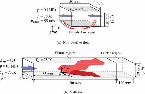
An auxiliary DNS of non-reacting flow is conducted before performing the DNS of V-flame, which is subsequently utilized for the specification of the inlet flow field for the reacting flow simulation. shows the computational domain and conditions for the DNS of non-reacting flow. This domain is taken to be a periodic channel flow for the purpose of generating a fully developed channel flow solution. For this part of the domain, the boundaries in the -direction are taken to be periodic, and thus, the flow conditions on the right-hand side boundary in
-direction are imposed on the left-hand boundary for the sake of periodicity. The flow conditions on the right-hand side boundary in
-direction are also used for specifying the inlet boundary condition for the reacting flow simulation. This treatment of inflow boundary condition is standard and was used in several previous analyses (Grout et al. Citation2012; Gruber et al. Citation2012, Citation2018; Minamoto et al. Citation2015; Wu et al. Citation2017). Using the above methodology, a fully developed wall-bounded turbulent flow is generated by imposing a periodic boundary condition in
-direction while maintaining a constant bulk velocity
of 55 m/s on the inlet plane. The inflow gas is the stoichiometric methane-air premixed gas at 750 K. The ambient pressure is taken to be 0.1 MPa. The no-slip isothermal (750 K) boundary condition is applied in
-direction, and the periodic boundary condition is applied in the
-direction. The isothermal wall boundary condition at 750 K has been used in several previous DNS studies (Ahmed, Chakraborty, and Klein Citation2021b; Alshaalan and Rutland Citation1998, Citation2002; Bruneaux et al. Citation1996; Bruneaux, Poinsot, and Ferziger Citation1997; Gruber et al. Citation2010) as most industrial combustor walls are maintained at a comparable temperature. The isothermal wall condition is an idealization, but any other condition (e.g., constant wall heat flux) involves as much idealization as that of the isothermal wall boundary condition. This is valid even for conjugate heat transfer, where the thermal boundary condition for a solid wall involves some degree of arbitrariness.
The friction Reynolds number for the current study is approximately 395, where
is the friction velocity,
is the channel half height, and
is the kinematic viscosity. The bulk Reynolds number
is approximately 14,500. The computational domain is discretized on a non-uniform staggered grid with a Cartesian coordinate system. For the turbulence generation region, the grid resolution is 250 µm in
-direction (
= 10), 10–30 µm from the wall to the center of the channel in
-direction (
= 0.4–1.2), and 30 µm in
-direction (
= 1.2). Here, the superscript
represents the wall-unit length. It should be noted that the region
(where
is the kinematic viscosity at the wall) has at least two grid points to ensure appropriate resolution of the boundary layer, as recommended by Moser, Kim, and Mansour (Citation1999).
shows the computational domain and conditions for the DNS of V-flame. The domain consists of two (flame and buffer) regions. The last 160 mm of the reacting simulation domain is kept as a buffer region so that the outflow boundary does not affect the reacting flow simulation, following previous analyses (Ahmed et al. Citation2019, Citation2020; Kitano et al. Citation2015). For the current analysis, the ratio of the friction velocity and the unstretched laminar burning velocity is (where
is the unstretched laminar burning velocity). Thus, no flashback is expected because
is not conducive to flashback in the case of hydrocarbon flames (Ahmed, Chakraborty, and Klein Citation2021b; Alshaalan and Rutland Citation1998, Citation2002; Gruber et al. Citation2010). The flame holder is placed in a fully developed wall-bounded turbulent flow to stabilize the flame and preclude any possibility of a flame blowout. It has been shown in previous studies (Ahmed, Chakraborty, and Klein Citation2021b; Alshaalan and Rutland Citation1998, Citation2002; Gruber et al. Citation2010) that a flame blowout is not expected in this configuration.
The flame holder is placed at 5 mm above the bottom wall ( = 197.5,
) and at 85 mm from the inlet plane by imposing a burned gas composition and temperature following an earlier unconfined V-flame investigation (Bell et al. Citation2005). The radius of the flame holder
is approximately 0.86
. Here,
is the laminar flame thermal thickness defined as
, where
is the temperature, and the subscript
represents values in the corresponding unstretched laminar premixed flame. The flame holder is placed close to the bottom wall such that the bottom branch of the V-flame interacts more readily with the wall. This is to avoid using a much longer domain in the
-direction, which would be necessary to achieve a substantial amount of FWI if the flame holder is placed at the middle of the channel. It is also worth noting that the flame holder remains far away from the region where FWI occurs and sufficiently away from the wall, and the viscous sublayer is not affected by the presence of the flame holder. This position of the flame holder does not affect the SDF statistics presented later in the paper, and previous analyses involving V-flame-wall interaction (Ahmed, Chakraborty, and Klein Citation2021b; Alshaalan and Rutland Citation1998; 2002Alshaalan and Rutland Citation2002) followed the same practice.
Figure 1. Schematics of computational domains and conditions for DNS of (a) non-reacting flow and (b) V-flame.
The computational domain for the V-flame region is discretized on a non-uniform staggered grid with a Cartesian coordinate system. The origin of the coordinate system is located at the flame holder in -direction, at the bottom wall in
-direction, and at the center in
-direction. The grid configuration in the
- and
-directions is the same as the DNS of non-reacting flow. The minimum grid spacing in
-direction is 30
m and is arranged from
to
. The
is resolved by approximately 10 grid points with this grid spacing. In the buffer region, the grid spacing in
-direction is stretched. At the inflow of the V-flame computational domain, the data from the non-reacting flow simulation are introduced along with all the species mass fractions, under non-reacting conditions, used in the V-flame calculation. At the outflow boundary, the pressure is constant at the ambient pressure of 0.1 MPa, and the Neumann boundary condition is imposed for the other physical quantities. The no-slip isothermal (750 K) boundary condition is applied on the boundaries in the
-direction. For the pressure and species mass fraction, Neumann boundary condition is imposed at the wall. The periodic boundary condition is applied in the
-direction.
The grid spacing in the V-flame simulation is chosen such that 10 grid points are kept within the thermal flame thickness and coarsening the mesh by a factor of 2 gave rise to
differences in the laminar burning velocity
. However, the finer grid is used in this study to ensure higher fidelity. Moreover, the grid spacing in all directions is chosen such that the viscous sublayer is well resolved, especially in the wall-normal direction where two points are kept within
, which ensures that the turbulent structures are sufficiently resolved and satisfy the criteria of Moser, Kim, and Mansour (Citation1999). It is worth noting that in channel flows, the root-mean-square velocity fluctuation
and integral length scale
scale with
and channel half-height
, respectively (Ahmed et al. Citation2021). This leads to a Karlovitz number of
, which suggests that the flame nominally represents the corrugated flamelets regime of combustion (Peters Citation2000), where the Kolmogorov length scale
remains larger than the flame thickness
(i.e.,
). This, furthermore, implies that the resolution of
by 10 grid points automatically ensures sufficient resolution of
away from the wall.
The numerical simulations are performed using the in-house code FK, which was used in several previous studies on FWI (Kai et al. Citation2020; Kitano et al. Citation2015; Yunoki et al. Citation2021). This code is based on a pressure-based semi-implicit solver for compressible flows, which employs a fractional-step method (Moureau, Bérat, and Pitsch Citation2007). The spatial derivative of the convective term in the momentum equation is approximated with a fourth-order central difference scheme. A fifth-order WENO scheme (Jiang and Shu Citation1996) is applied to approximate the spatial derivatives of the convective terms in the governing equations of the scalar quantities. In the vicinity of the wall, a third-order one-sided scheme is used to evaluate the spatial derivatives. An iterative method is used to solve the Helmholtz equation for pressure correction, and a scaled convergence criterion of
is used for this purpose. For all other conservation equations, a third-order explicit TVD-range Runge-Kutta time advancement has been adopted with a time step size of 0.1 µs. The simulation was run for two throughpass times based on the bulk velocity. It was checked that the Reynolds averaged values based on time-averaging between 1 and 1.5 and 1.5 to 2 throughpass times did not change appreciable (
) to ensure statistical stationarity was obtained. The CPU times required for the DNS of non-reacting flow and V-flame were approximately 0.25 and 1.26 million hours by parallel computation with 1,488 and 3,000 cores (actual wall clock time was 168 and 420 h) for 0.18 billion and 1.23 billion grid points, respectively. The DNS utilized the computational resources of the Cray XC40 supercomputer at Kyoto University and the supercomputer Fugaku at the RIKEN Center for Computational Science.
Results and discussion
Flow field and flame behavior
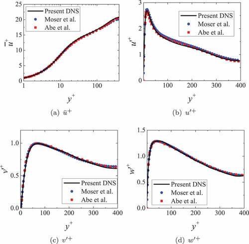
shows the profiles of the mean streamwise velocity and root mean square values of velocity fluctuations in the wall-normal direction obtained by the DNS of non-reacting flow. The obtained results are compared with the previous DNS results of Moser, Kim, and Mansour (Citation1999) and Abe, Kawamura, and Matsuo (Citation2001) at . The profiles of the present DNS match well with previously reported results. It is important to note that the small differences between the current and the previous results are comparable to those by several other authors (Abe, Kawamura, and Matsuo Citation2001; Grout et al. Citation2012; Gruber et al. Citation2010; Peeters and Sandham Citation2019), and this difference can further be reduced by a longer time averaging.
Figure 2. Profiles of (a) mean mainstream velocity, , and (b)-(d) root mean square values of velocity fluctuations,
,
,
, in wall-normal direction for DNS of non-reacting flow. The results of the present DNS are compared with the previous DNS by Moser, Kim, and Mansour (Citation1999) and by Abe, Kawamura, and Matsuo (Citation2001).
It is instructive to consider a quenching Peclet number to quantify the flame-quenching behavior due to wall heat loss. The quenching Peclet number
is the normalized value of quenching distance
and is defined using the Zel’dovich flame thickness
as
, where
is the thermal diffusivity for unburned gas. In this study,
is defined as the minimum wall-normal distance to the isosurface of nondimensional temperature
, as the maximum heat release rate in the unstretched laminar premixed flame for the present thermochemistry occurs close to
. The minimum
for the present DNS at
is 1.96, which is close to the minimum
of 2.02 at
from the previous study (Ahmed, Chakraborty, and Klein Citation2021b). The minimum
for the one-dimensional HOQ flame is also calculated as 2.20, which is almost the same as the 2.19 obtained in the previous study (Ahmed, Chakraborty, and Klein Citation2021b).
shows the Favre averaged distributions of temperature, enthalpy, heat release rate, and mass fractions of the fuel (i.e., ) and species (i.e.,
), from which the reaction progress variable
is defined. It can be seen from that the enthalpy deficit (here, the enthalpy deficit
is defined as
, where
is the adiabatic specific enthalpy) close to the wall becomes significant for
, which is indicative of the heat loss through the isothermal wall. This is also indicative of the thermal boundary layer formation on the bottom wall. The thickness of the low enthalpy layer on the bottom wall increases in the region given by
, and at
, and the effects of heat loss can be observed up to
(
) from the bottom wall surface. It can further be seen from that the mean heat release rate disappears near the wall for
as a result of heat loss through the isothermal wall. The same inferences can be drawn from , which shows the instantaneous distributions of the variables shown in at
exemplarily at
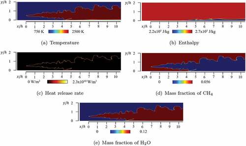
4.45 ms, but the instantaneous distributions remain qualitatively similar at other time instances due to the statistical stationarity of this configuration.
Figure 3. Favre-averaged distributions of (a) temperature, (b) enthalpy, (c) heat release rate, (d) mass fraction of , and (e) mass fraction of
.
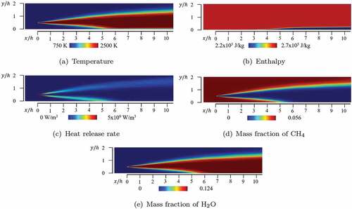
Figure 4. Instantaneous distributions of (a) temperature, (b) enthalpy, (c) heat release rate, (d) mass fraction of , and (e) mass fraction of
on the
-
plane at
0 at
4.45 ms.
To demonstrate the intermittent nature of FWI induced by the vortical structure in the vicinity of the wall, shows the time series of the isosurfaces of and the second invariant of velocity gradient tensor for incompressible fluids
near the bottom wall. Here, the second invariant of the velocity gradient tensor for incompressible fluids
is used because it is defined as
, where
and
are the strain rate and rotation rate tensors, respectively. Thus, strain rate-dominated (
) and vorticity-dominated (
) regions can easily be demarcated using
. demonstrates that the
isosurface protrudes forward and upward in the vicinity of the wall due to near-wall turbulent structures (e.g., wall ejections). High magnitudes of vorticity are observed on the unburned side of the protruded isosurface of
as vorticity magnitude drops from the unburned to burned gas side as a result of the increase in kinematic viscosity in the burned gas and predominantly positive values of dilatation rate. An occurrence of flame folding is observed at approximately
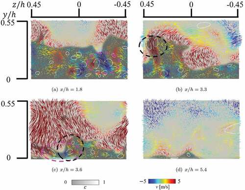
, where the unburned methane pockets appear surrounded by the burned gas. In the downstream, the isolated unburned gas pockets are consumed away from the wall where heat loss effects remain weak. shows the instantaneous distributions of
, isoline of
, and velocity vector colored by
-component of velocity vector on
-
planes at
, 3.3, 3.6, and 5.4. The locations of these cross-sections are shown in . The magenta and black circles in indicate sweep and ejection events, respectively. It can be discerned from that the sweep events promote flame propagation toward the wall, whereas the ejection events raise unburned gas away from the wall, as observed in previous studies (Alshaalan and Rutland Citation1998; Bruneaux et al. Citation1996).
Figure 5. Instantaneous isosurfaces of reaction progress variable ( 0.5, colored in red) and the incompressible definition of the second invariant of velocity gradient tensor (
, colored in green for
0.5, colored in white for
0.5) near bottom wall at (a)
4.30 ms, (b) 4.35 ms, and (c) 4.40 ms. The cross-sections shown in are shown later in .
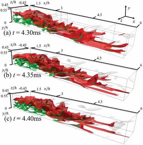
Figure 6. Instantaneous distributions of reaction progress variable , isolines of the incompressible definition of the second invariant of velocity gradient tensor (
, colored in white), and velocity vectors on the
-
plane colored by the
-component of velocity vector
at
(a) 1.8, (b) 3.3, (c) 3.6, and (d) 5.4 at
4.3 ms. Location of each cross-section are shown in . Magenta and black circles show sweep and ejection events.
Influence of near wall vortical structure on the evolution of SDF
It can be inferred from EquationEq. (6)(6)
(6) that the strain rates and flame curvatures induced by the local flow features can potentially significantly affect the SDF evolution. Hence, it is useful to investigate the effects of near-wall vortical structure on the SDF and the associated strain rates, which dictate the SDF evolution, and this aspect is addressed in this subsection. shows instantaneous distributions of the SDF on
-
plane at
and on
-
plane at
with isoline
, exemplarily at
4.45 ms, but qualitatively similar behavior has been observed at other time instances. These figures clearly show that the SDF assumes peak values close to
away from the wall. However, in the vicinity of the wall, the SDF remains small, even close to
. To focus on the region where the SDF assumes non-negligible values, the instantaneous distributions of
, heat release rate, enthalpy deficit
, and normalized values of
,
, and
for the region corresponding to the normalized SDF
at
are shown in . The corresponding distributions on
-
plane at
are shown in . It can be seen from that
assumes positive peak values near the isoline of
away from the wall where the thermal expansion effects remain strong. By contrast, negative peak values of
are obtained close to
, which indicates an increasing trend of the displacement speed
from the unburned to burned gas side of the flame due to the density variation as a result of thermal expansion. The relative magnitudes of
and
lead to large positive values of
on both the product and reactant sides of the unburned gas pocket that can be observed at
. In the vicinity of the wall, despite being near the isoline of
, the SDF has small values if the enthalpy deficit is large and heat release rate effects are weak, as shown in . In addition to the heat loss, the flame structure also affects the magnitude of the SDF. At approximately
and
, for example, the SDF becomes smaller than that in the region where the reaction progress variable
and enthalpy deficit have the same magnitudes. This is because the upstream and downstream flame surfaces of the flame fold merge, resulting in the formation of a saddle point of
. The normal strain rate
assumes negative values in the downstream of
close to the wall (e.g.
), but the normal strain rate remains predominantly positive away from the wall. It was demonstrated earlier in that the unburned gas protrudes forward and upward near the wall. As the heat release rate on the upper side of the protruded unburned gas pocket is larger than that of the lower side because of the lower heat loss, the stronger thermal expansion of the upper side generates flow toward the wall. The flow acceleration induced by the upper side of the protruded unburned gas pocket and zero velocity on the wall surface result in negative
values downstream of the
isoline, which corresponds to the flame surface belonging to the lower side of the protruded unburned gas. The additional strain rate induced by flame propagation
assumes mostly positive values in the near-wall region, but negative values are obtained where the effects of heat release are strong (see ). Regarding
, the negative value of
downstream of the
isoline results in negative
in the same region. For positive
, the contribution of
is dominant, except in the low heat loss region (see ).
Figure 7. Close-up views of instantaneous distributions of normalized surface density function on (a) the
-
plane at
, and (b) on the
-
plane at
at
4.45 ms. Black line represents isoline of reaction progress variable
.

Figure 8. Instantaneous distributions of (a) reaction progress variable , (b) heat release rate, (c) enthalpy deficit, normalized values of (d)
, (e)
, and (f)
on the
-
plane at
near-wall for the region given by
at
4.45 ms. Black line represents isoline of reaction progress variable
.
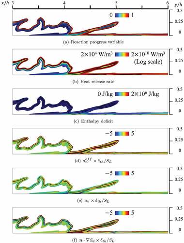
Figure 9. Instantaneous distributions of (a) reaction progress variable , (b) heat release rate, (c) enthalpy deficit, normalized values of (d)
, (e)
, and (f)
on the
-
plane at
for the region given by
at
4.45 ms. Black line represents isoline of reaction progress variable
.
Mean behavior of SDF and associated strain rates
In light of the local behaviors of the SDF and strain rates affecting the SDF evolution, the following discussion focuses on the statistical behaviors of these quantities because of their importance to FSD- and SDR-based modeling of FWI.
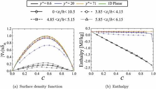
shows the mean values of normalized SDF and enthalpy conditioned on
. These mean values are evaluated by time averaging the samples for a given
value between 1 and 2 throughpass times in this statistically stationary configuration. Thus, no time value is mentioned for , and subsequent figures show mean values conditioned upon
. The mean values in the viscous sublayer (at
), buffer layer (at
), and outer layer (at
) are compared to investigate the effect of heat loss through the isothermal wall. Moreover, the mean values are calculated for different ranges of
because the statistical behaviors of the SDF and strain rates, which affect its evolution during FWI, change with the streamwise distance from the flame holder. For comparison, the SDF profile for one-dimensional unstretched laminar premixed flame is also shown in . The mean value of SDF in the outer layer (at
) matches that of one-dimensional laminar planar flame, whereas the mean values of SDF in the buffer layer (at
) and viscous sublayer (at
) are almost 90% and 10% of that of the planar flame, respectively. In all three layers, the mean value of SDF for a given value of
has been found to decrease in the downstream direction with the progress of flame quenching. The heat loss is negligible at
, and the enthalpy decreases as
increases at
and 20, which can be substantiated from . In all three layers, the mean value of enthalpy decreases in the downstream direction as a result of wall heat loss and flame quenching. In the upstream region, the unburned gas has the same temperature as the wall, which makes the heat loss in the upstream region smaller than that in the downstream region. Moreover, comparison of mean SDF and mean enthalpy implies that the small values of the SDF are associated with weakening of the reaction rate effects due to heat loss through the wall.
Figure 10. Mean values of (a) normalized surface density function , and (b) enthalpy conditioned upon reaction progress variable
at different wall-normal distances of
0.6, 20, 71 for different streamwise locations.
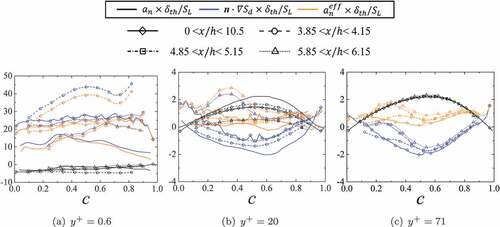
shows the mean values of ,
, and
conditioned on
at different wall-normal distances for different streamwise locations. The mean value of effective normal strain rate
, which acts to reduce the value of SDF with its increase (see EquationEq. (7)
(7)
(7) ), is significantly higher at
than at
and 21. This means that the SDF sharply decreases in the viscous sublayer, in which the contribution of
to
is more dominant than that of normal strain rate
. The results shown in are spatially averaged over the span of
at
and 20 to compare with the results reported by Ahmed, Chakraborty, and Klein (Citation2021b) for
. In the buffer layer (e.g., at
), the magnitudes of
and
around
for
are smaller than those for
. At
,
-
plane at
corresponds to more than 3.5 times closer to the wall in terms of wall-normal distance compared to at
, which gives rise to the suppression of reaction in the buffer layer more in the case of higher
due to more heat loss from the closer proximity to the wall. As a result, at
, the effective normal strain rate
takes positive values, and accordingly, the SDF decreases in the buffer layer. Meanwhile, at
,
remains close to zero, and accordingly, the SDF does not change. These behaviors for
at
are similar to the results for
at
, where the heat loss effects are negligible, as shown in . In the viscous sublayer (e.g., at
), the aforementioned dominance of the contribution of
to
for
is qualitatively similar to the analysis of the previous study (Ahmed, Chakraborty, and Klein Citation2021b) for
. However, the maximum value of
for
is approximately twice that for
, which causes a marked decrease in the SDF in the viscous sublayer at higher
. It is worth noting that the effective normal strain rate
has both fluid dynamic (i.e.,
) and flame propagation (i.e.,
) contributions. Modification of the turbulence level with
can affect the magnitude of
, but the sign of
and contributions of
and
are determined by small-scale physics that cannot be a-priori predicted solely based on Reynolds number. The reaction rate effects remain weak close to the wall due to flame quenching, which also weakens the influence of thermal expansion. These combinations can lead to positive mean values of
close to the wall, but the mean value of
remains negative away from the wall due to the increase in
from the unburned to burned gas side of the flame front. Accordingly,
assumes large positive mean values close to the wall (i.e., in the viscous sublayer).
Figure 11. Mean normalized values of ,
, and
conditioned upon
at (a)
, (b)
, and (c)
for different streamwise locations. Lines without symbol in (a) and (b) represent results by Ahmed, Chakraborty, and Klein (Citation2021b) for
. No data for
was reported in Ahmed, Chakraborty, and Klein (Citation2021b) and thus it is not shown in (c).
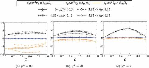
The normal strain rate can be expressed as (Ahmed et al. Citation2020; Ahmed, Chakraborty, and Klein Citation2021b; Dopazo et al. Citation2015)
Here, ,
, and
are the most extensive, intermediate, and the most compressive principal strain rates, and
,
, and
are the angles of
with the eigenvectors associated with
,
, and
, respectively. The reaction progress variable gradient
aligns preferentially with the eigenvector associated with
when the strain rate induced by flame normal acceleration dominates over turbulent straining (Ahmed, Chakraborty, and Klein Citation2021b; Ahmed, Prosser, and Revell Citation2014; Chakraborty and Swaminathan Citation2007; Kim and Pitsch Citation2007), which is highly probable for the flames with Damköhler number
. On the contrary,
aligns with the eigenvector associated with
when the contribution of turbulent straining dominates the straining due to flame normal acceleration (Ahmed, Chakraborty, and Klein Citation2021b; Ahmed, Prosser, and Revell Citation2014; Chakraborty and Swaminathan Citation2007; Kim and Pitsch Citation2007), which is highly probable for
. shows the mean values of
,
, and
conditioned on
at different wall-normal distances for different streamwise locations. In the outer layer (at
), the mean value of
is higher than that of
, which is consistent with the positive mean value of
(see ). The magnitude of the negative mean contribution of
increases with decreasing wall-normal distance, but the mean value of
does not change much. In the viscous sublayer (at
), the magnitude of positive mean values of
is smaller than that of the negative mean values of
, which results in the negative mean values of
, as shown in . This is a consequence of weakening thermal expansion effects due to the reduced reaction rate caused by the wall heat loss. Although the mean
remains negative, this contribution is dominated significantly by large positive mean values of
, which results in large positive mean values of
. This large mean positive value of
in the vicinity of the wall (i.e.,
) gives rise to a significant drop in the mean value of
according to EquationEq. (7)
(7)
(7) (see ).
Figure 12. Mean values of normalized ,
, and
conditioned upon reaction progress variable
at (a)
, (b)
, and (c)
for different streamwise locations.
Modeling implications
It is possible to obtain the transport equation of the generalized FSD (i.e. ) (Boger et al. Citation1998) on Reynolds averaging/LES filtering (EquationEq. 6)
(6)
(6) as
Moreover, multiplying EquationEq. (6)(6)
(6) by
yields
Algebraic manipulation of EquationEq. (10)(10)
(10) provides the transport equation of SDR
and
(Chakraborty et al. Citation2011; Klein, Alwazzan, and Chakraborty Citation2018):
It is evident from EquationEqs. (9)(9)
(9) –(Equation12
(12)
(12) ) that
,
and
play key roles in both FSD and SDR transports. The present analysis suggests that the near-wall behaviors of
,
, and
ultimately govern the statistical behaviors of
and
in the vicinity of the wall during FWI. Thus, the statistical behaviors of the unclosed terms on the right-hand side of EquationEqs. (9)
(9)
(9) and (Equation12
(12)
(12) ) need to be modeled by accounting for the effects of wall-induced shear and flame quenching to obtain accurate predictions of
and
during FWI.
The observations made from suggest that the presence of wall affects the statistical behaviors of and
, which in turn affect the evolutions of the FSD
and Favre-averaged SDR
as can be seen from EquationEqs. (9)
(9)
(9) and (Equation12
(12)
(12) ). As
and
are needed for mean reaction rate closures (Boger et al. Citation1998; Chakraborty et al. Citation2011; Vervisch et al. Citation2011) in both RANS and LES, it is important to capture their near-wall behaviors in order to capture the species and temperature distributions within turbulent boundary layers during flame–wall interaction. It is also worth noting that the knowledge of
is also necessary for scalar variance
(Chakraborty and Swaminathan Citation2011; Lai and Chakraborty Citation2016b) and conditional SDR
in the context of CMC closures (Klimenko and Bilger Citation1999). Thus, the contributions arising from
and
in the FSD and SDR transport equations need to be modeled in such a manner that their near-wall behaviors are captured for satisfactory performance of FSD-, SDR-, and CMC-based closures in the context of RANS and LES.
Conclusions
In this study, a three-dimensional DNS of a turbulent stoichiometric methane-air premixed V-flame interacting with an isothermal wall in a turbulent channel flow configuration at friction Reynolds number was performed employing a two-step global reaction mechanism (Bibrzycki and Poinsot Citation2010). The DNS data has been utilized to analyze flame–turbulence interaction and statistical behavior of surface density function (SDF) in the vicinity of the wall. It has been found that the streamwise vortices strongly affect the flame behavior near the wall. In particular, the sweep events enhanced flame propagation toward the wall, and the ejection events raised unburned gas away from the wall. Some of the unburned gas raised by the ejection events gave rise to the unburned gas pockets in the downstream region.
The statistical behaviors of the SDF, effective normal strain rate , normal strain rate
, and the additional strain rate induced by flame propagation
were investigated in reaction progress variable
space at different wall-normal distances and streamwise locations. The mean value of SDF in the outer layer (at
) in reaction progress variable space agrees well with that of a one-dimensional unstretched laminar premixed flame, whereas the mean values of the SDF in the buffer layer (at
) and viscous sublayer (at
) were almost 90% and 10% of that of the unstretched planar laminar premixed flame, respectively. In all zones of the turbulent boundary layer, the mean value of the SDF conditional upon
has been found to decrease in the downstream direction with the progress of flame quenching. These results suggest that the mean value of SDF is strongly affected by the heat loss through the wall.
The mean value of effective normal strain rate (
), which acts to decrease the SDF with its increase, has been found to be much greater at
than at
and 21. This gives rise to a sharp decrease of the SDF in the viscous sublayer. In the viscous sublayer, the contribution of
to
has been found to dominate over the fluid-dynamic normal strain rate
. This tendency is qualitatively similar to the results from a previous analysis (Ahmed, Chakraborty, and Klein Citation2021b) at
. However, the maximum value of
for
is found to be approximately twice that obtained for
, which causes a marked decrease in the SDF in the viscous sublayer for higher values of
. In all three layers, the local mean values of
and
decrease in the downstream direction with the progress of flame quenching.
Thus, at , the statistical values related to the SDF evolution are quantitatively different from those at
, although the reduction of the SDF in the viscous sublayer arises mainly because of the strain rate induced by displacement speed rather than fluid-dynamic strain rate in this configuration which is qualitatively similar to previous findings (Ahmed, Chakraborty, and Klein Citation2021b) for
.
It is worth noting that the present analysis has been conducted for atmospheric pressure. The laminar burning velocity and flame thickness decrease with increasing pressure. Thus, the quenching distance is expected to decrease with an increase in pressure. Moreover, for a given flow condition (i.e., bulk flow velocity) the bulk Reynolds number is expected to increase with increasing pressure, which also suggests that the boundary layer thickness is expected to decrease with an increase in pressure. However, the flow statistics in turbulent boundary layers reach mostly a self-similar state for (Abe, Kawamura, and Matsuo Citation2001; Ahmed et al. Citation2021; Moser, Kim, and Mansour Citation1999) and the Peclet number (i.e., quenching distance normalized by the flame thickness) is not affected by pressure. Therefore, flame–wall interaction takes place roughly in the same range of
for elevated pressures. Thus, the current findings considered in the nondimensional forms in terms of wall units are still expected to remain valid for elevated pressure conditions at least in a qualitative sense because a previous analysis (Klein, Alwazzan, and Chakraborty Citation2018) in the absence of walls revealed the qualitative nature of the SDF statistics does not change for elevated pressure levels. However, for further understanding of the statistical behaviors of different strain rates on the SDF evolution near the wall, analyses of other FWI configurations at high values of
and elevated thermodynamic pressure levels will be necessary, which will form the basis for further investigation.
Disclosure statement
No potential conflict of interest was reported by the author(s).
Additional information
Funding
References
- Abe, H., H. Kawamura, and Y. Matsuo. 2001. Direct numerical simulation of a fully developed turbulent channel flow with respect to the Reynolds number dependence. J. Fluids Eng. 123 (2):382. doi:10.1115/1.1366680.
- Ahmed, U., D. Apsley, T. Stallard, P. K. Stansby, and I. Afgan. 2021. Turbulent length scales and budgets of Reynolds stress-transport for open-channel flows; friction Reynolds numbers Reτ = 150, 400 and 1020. J. Hydraul. Res. 59 (1):36–50. doi:10.1080/00221686.2020.1729265.
- Ahmed, U., N. Chakraborty, and M. Klein. 2021a. Assessment of bray moss Libby formulation for premixed flame-wall interaction within turbulent boundary layers: Influence of flow configuration. Combust. Flame 233:111575. doi:10.1016/j.combustflame.2021.111575.
- Ahmed, U., N. Chakraborty, and M. Klein. 2021b. Scalar gradient and strain rate statistics in oblique premixed flame–wall interaction within turbulent channel flows. Flow Turbul.Combust. 106 (2):701–32. doi:10.1007/s10494-020-00169-3.
- Ahmed, U., N. A. K. Doan, J. Lai, M. Klein, N. Chakraborty, and N. Swaminathan. 2018. Multiscale analysis of head-on quenching premixed turbulent flames. Phys. Fluids 30 (10):105102. doi:10.1063/1.5047061.
- Ahmed, U., A. L. Pillai, N. Chakraborty, and R. Kurose. 2019. Statistical behavior of turbulent kinetic energy transport in boundary layer flashback of hydrogen-rich premixed combustion. Phys. Rev. Fluids 4 (10):103201. doi:10.1103/PhysRevFluids.4.103201.
- Ahmed, U., A. L. Pillai, N. Chakraborty, and R. Kurose. 2020. Surface density function evolution and the influence of strain rates during turbulent boundary layer flashback of hydrogen-rich premixed combustion. Phys. Fluids 32 (5):055112. doi:10.1063/5.0004850.
- Ahmed, U., R. Prosser, and A. J. Revell. 2014. Towards the development of an evolution equation for flame turbulence interaction in premixed turbulent combustion. Flow Turbul. Combust. 93 (4):637–63. doi:10.1007/s10494-014-9557-1.
- Alshaalan, T. M., and C. J. Rutland. 1998. Turbulence, scalar transport, and reaction rates in flame-wall interaction. Proc. Combust. Inst. 27 (1):793–99. doi:10.1016/S0082-0784(98)80474-8.
- Alshaalan, T. M., and C. J. Rutland. 2002. Wall heat flux in turbulent premixed reacting flow. Combust. Sci. Technol. 174 (1):135–65. doi:10.1080/713712913.
- Bell, J. B., M. S. Day, I. Shepherd, M. R. Johnson, R. K. Cheng, J. F. Grcar, and V. E. Beckner, M. J. Lijewski. 2005. Numerical simulation of a laboratory-scale turbulent V-flame. Proc. Natl. Acad. Sci. 102 (29):10006–11. doi:10.1073/pnas.0504140102.
- Bibrzycki, J., and T. Poinsot. 2010. Reduced chemical kinetic mechanisms for methane combustion in O2/N2 and O2/CO2 atmosphere. Work. note ECCOMET WN/CFD/10/17, CERFACS.
- Boger, M., D. Veynante, H. Boughanem, and A. Trouvé. 1998. Direct numerical simulation analysis of flame surface density concept for large eddy simulation of turbulent premixed combustion. Proc. Combust. Inst. 27 (1):917–25. doi:10.1016/S0082-0784(98)80489-X.
- Borghi, R., and D. Dutoya. 1979. On the scales of the fluctuations in turbulent combustion. Proc. Combust. Inst. 17 (1):235–44. doi:10.1016/S0082-0784(79)80025-9.
- Bruneaux, G., K. Akselvoll, T. Poinsot, and J. Ferziger. 1996. Flame-wall interaction simulation in a turbulent channel flow. Combust. Flame 107 (1–2):27–44. doi:10.1016/0010-2180(95)00263-4.
- Bruneaux, G., T. Poinsot, and J. Ferziger. 1997. Premixed flame–wall interaction in a turbulent channel flow: Budget for the flame surface density evolution equation and modelling. J. Fluid Mech. 349:191–219. doi:10.1017/S0022112097006769.
- Chakraborty, N., M. Champion, A. Mura, and N. Swaminathan. 2011. Scalar dissipation rate approach to reaction rate closure”, turbulent premixed flame. In Turbulent premixed flame, ed. N. Swaminathan and K. N. C. Bray, 74–102. New York: Cambridge University Press.
- Chakraborty, N., M. Klein, D. Alwazzan, and H. G. Im. 2018. Surface density function statistics in hydrogen-air flames for different turbulent premixed combustion regimes. Combust. Sci. Technol. 190 (11):1988–2002. doi:10.1080/00102202.2018.1480015.
- Chakraborty, N., and N. Swaminathan. 2007. Influence of the Damköhler number on turbulence-scalar interaction in premixed flames. I. physical insight. Phys. Fluids 19 (4):045103. doi:10.1063/1.2714070.
- Chakraborty, N., and N. Swaminathan. 2011. Effects of Lewis number on scalar variance transport in turbulent premixed flames. Flow, Turb. Combust. 87 (2–3):261–92. doi:10.1007/s10494-010-9305-0.
- Dabireau, F., B. Cuenot, O. Vermorel, and T. Poinsot. 2003. Interaction of flames of H2+O2 with inert walls. Combust. Flame 135 (1–2):123–33. doi:10.1016/S0010-2180(03)00154-8.
- Domingo, P., and L. Vervisch. 2022. Recent developments in DNS of turbulent combustion. Proc. Combust. Inst. 39. doi:10.1016/j.proci.2022.06.030.
- Dopazo, C., L. Cifuentes, J. Martin, and C. Jimenez. 2015. Strain rates normal to approaching ISO-scalar surfaces in a turbulent premixed flame. Combust. Flame 162 (5):1729–36. doi:10.1016/j.combustflame.2014.11.034.
- Echekki, T., and J. H. Chen. 1996. Unsteady strain rate and curvature effects in turbulent premixed methane-air flames. Combust. Flame 106 (1–2):184–202. doi:10.1016/0010-2180(96)00011-9.
- Eichler, C., G. Baumgartner, and T. Sattelmayer. 2012. Experimental investigation of turbulent boundary layer flashback limits for premixed hydrogen-air flames confined in ducts. J. Eng. Gas Turbines Power 134 (1). doi:10.1115/1.4004149.
- Goldmann, A., and F. Dinkelacker. 2021. Experimental investigation and modeling of boundary layer flashback for non-swirling premixed hydrogen/ammonia/air flames. Combust. Flame 226:362–79. doi:10.1016/j.combustflame.2020.12.021.
- Grout, R. W., A. Gruber, H. Kolla, P.-T. Bremer, J. C. Bennett, A. Gyulassy, and J. H. Chen. 2012. A direct numerical simulation study of turbulence and flame structure in transverse jets analysed in jet-trajectory based coordinates. J. Fluid. Mech. 706:351–83. doi:10.1017/jfm.2012.257.
- Gruber, A., J. H. Chen, D. Valiev, and C. K. Law. 2012. Direct numerical simulation of premixed flame boundary layer flashback in turbulent channel flow. J. Fluid Mech. 709:516–42. doi:10.1017/jfm.2012.345.
- Gruber, A., E. S. Richardson, K. Aditya, and J. H. Chen. 2018. Direct numerical simulations of premixed and stratified flame propagation in turbulent channel flow. Phys. Rev. Fluids 3 (11):110507. doi:10.1103/PhysRevFluids.3.110507.
- Gruber, A., R. Sankaran, E. Hawkes, and J. Chen. 2010. Turbulent flame–wall interaction: A direct numerical simulation study. J. Fluid Mech. 658:5–32. doi:10.1017/S0022112010001278.
- Jainski, C., M. Rißmann, B. Böhm, and A. Dreizler. 2017. Experimental investigation of flame surface density and mean reaction rate during flame–wall interaction. Proc. Combust. Inst. 36 (2):1827–34. doi:10.1016/j.proci.2016.07.113.
- Jiang, B., D. Brouzet, M. Talei, R. L. Gordon, Q. Cazeres, and B. Cuenot. 2021. Turbulent flame-wall interactions for flames diluted by hot combustion products. Combust. Flame 230:111432. doi:10.1016/j.combustflame.2021.111432.
- Jiang, B., R. Gordon, and M. Talei. 2019. Head-on quenching of laminar premixed methane flames diluted with hot combustion products. Proc. Combust. Inst. 37 (4):5095–103. doi:10.1016/j.proci.2018.07.120.
- Jiang, and C.-W. Shu. 1996. Efficient Implementation of weighted ENO Schemes. J. Compt. Phys. 126 (1):202–28. doi:10.1006/jcph.1996.0130.
- Kai, R., R. Masuda, T. Ikedo, and R. Kurose. 2020. Conjugate heat transfer analysis of methane/air premixed flame–wall interaction: A study on effect of wall material. Appl. Therm. Eng. 181:115947. doi:10.1016/j.applthermaleng.2020.115947.
- Keil, F. B., M. Amzehnhoff, U. Ahmed, N. Chakraborty, and M. Klein. 2021a. Comparison of flame propagation statistics based on direct numerical simulation of simple and detailed chemistry. Part 2: Influence of choice of reaction progress variable. Energies 14 (18):5695. doi:10.3390/en14185695.
- Keil, F. B., M. Amzehnhoff, U. Ahmed, N. Chakraborty, and M. Klein. 2021b. Comparison of flame propagation statistics extracted from direct numerical simulation based on simple and detailed chemistry-Part 1: Fundamental flame turbulence interaction. Energies 14 (17):5548. doi:10.3390/en14175548.
- Kim, S. H., and H. Pitsch. 2007. Scalar gradient and small-scale structure in turbulent premixed combustion. Phys. Fluids 19 (11):115104. doi:10.1063/1.2784943.
- Kitano, T., T. Tsuji, R. Kurose, and S. Komori. 2015. Effect of pressure oscillations on flashback characteristics in a turbulent channel flow. Energy Fuels 29 (10):6815–22. doi:10.1021/acs.energyfuels.5b01687.
- Klein, M., D. Alwazzan, and N. Chakraborty. 2018. A direct numerical simulation analysis of pressure variation in turbulent premixed bunsen burner flames-part 1: Scalar gradient and strain rate statistics. Comput. Fluids 173:178–88. doi:10.1016/j.compfluid.2018.03.010.
- Klimenko, A. Y., and R. W. Bilger. 1999. Conditional moment closure for turbulent combustion. Prog. Energy Combust. Sci. 25 (6):595–687. doi:10.1016/S0360-1285(99)00006-4.
- Kollmann, W., and J. H. Chen. 1998. Pocket formation and the flame surface density equation. Proc. Combust. Inst. 27 (1):927–34. doi:10.1016/S0082-0784(98)80490-6.
- Konstantinou, I., U. Ahmed, and N. Chakraborty. 2021. Effects of fuel Lewis number on the near-wall dynamics for statistically planar turbulent premixed flames impinging on inert cold walls. Combust. Sci. Technol. 193 (2):235–65. doi:10.1080/00102202.2020.1799201.
- Kosaka, H., F. Zentgraf, A. Scholtissek, C. Hasse, and A. Dreizler. 2020. Effect of flame-wall interaction on local heat release of methane and dme combustion in a side-wall quenching geometry. Flow Turbul. Combust. 104 (4):1029–46. doi:10.1007/s10494-019-00090-4.
- Lai, J., and N. Chakraborty. 2016a. Effects of Lewis number on head on quenching of turbulent premixed flames: A direct numerical simulation analysis. Flow Turbul. Combust. 96 (2):279–308. doi:10.1007/s10494-015-9629-x.
- Lai, J., and N. Chakraborty. 2016b. Modelling of progress variable variance transport in head on quenching of turbulent premixed flames: A direct numerical simulation analysis. Combust. Sci. Technol. 188 (11–12):1925–50. doi:10.1080/00102202.2016.1211868.
- Lai, J., and N. Chakraborty. 2016c. A priori direct numerical simulation modeling of scalar dissipation rate transport in head-on quenching of turbulent premixed flames. Combust. Sci. Technol. 188 (9):1440–71. doi:10.1080/00102202.2016.1195823.
- Lai, J., N. Chakraborty, and A. Lipatnikov. 2017. Statistical behaviour of vorticity and enstrophy transport in head-on quenching of turbulent premixed flames. Eur. J. Mech. B Fluids 65:384–97. doi:10.1016/j.euromechflu.2016.10.013.
- Lai, J., M. Klein, and N. Chakraborty. 2018. Direct numerical simulation of head-on quenching of statistically planar turbulent premixed methane-air flames using a detailed chemical mechanism. Flow Turbul. Combust. 101 (4):1073–91. doi:10.1007/s10494-018-9907-5.
- Lai, J., D. H. Wacks, and N. Chakraborty. 2018. Flow topology distribution in head-on quenching of turbulent premixed flame: A direct numerical simulation analysis. Fuel 224:186–209. doi:10.1016/j.fuel.2018.03.021.
- Minamoto, Y., H. Kolla, R. W. Grout, A. Gruber, and J. H. Chen. 2015. Effect of fuel composition and differential diffusion on flame stabilization in reacting syngas jets in turbulent cross-flow. Combust. Flame 162 (10):3569–79. doi:10.1016/j.combustflame.2015.06.013.
- Moser, R. D., J. Kim, and N. N. Mansour. 1999. Direct numerical simulation of turbulent channel flow up to re τ = 590. Phys. Fluids 11 (4):943–45. doi:10.1063/1.869966.
- Moureau, V., C. Bérat, and H. Pitsch. 2007. An efficient semi-implicit compressible solver for large-eddy simulations. J. Compt. Phys. 226 (2):1256–70. doi:10.1016/j.jcp.2007.05.035.
- Palulli, R., M. Talei, and R. L. Gordon. 2019. Unsteady flame–wall interaction: Impact on co emission and wall heat flux. Combust. Flame 207:406–16. doi:10.1016/j.combustflame.2019.06.012.
- Peeters, J., and N. D. Sandham. 2019. Turbulent heat transfer in channels with irregular roughness. Int. J. Heat Mass Transf. 138:454–67. doi:10.1016/j.ijheatmasstransfer.2019.04.013.
- Peters, N. 2000. Turbulent Combustion. New York: Cambridge University Press.
- Poinsot, T., D. C. Haworth, and G. Bruneaux. 1993. Direct simulation and modeling of flamewall interaction for premixed turbulent combustion. Combust. Flame 95 (1–2):118–32. doi:10.1016/0010-2180(93)90056-9.
- Poinsot, T., and D. Veynante. 2005. Theoretical and numerical combustion. Philadelphia: RT Edwards, Inc.
- Sellmann, J., J. Lai, A. M. Kempf, and N. Chakraborty. 2017. Flame surface density based modelling of head-on quenching of turbulent premixed flames. Proc. Combust. Inst. 36 (2):1817–25. doi:10.1016/j.proci.2016.07.114.
- Turquand d’Auzay, C., V. Papapostolou, S. F. Ahmed, and N. Chakraborty. 2019. Effects of turbulence intensity and biogas composition on the localized forced ignition of turbulent mixing layers. Combust. Sci. Technol. 191 (5–6):868–97. doi:10.1080/00102202.2019.1576651.
- Vervisch, L., V. Moureau, P. Domingo, and D. Veynante. 2011. Flame surface density and the g equation, turbulent premixed flame. In Turbulent premixed flame, ed. N. Swaminathan and K. N. C. Bray, 61–73. New York: Cambridge University Press.
- Vosen, S., R. Greif, and C. K. Westbrook. 1985. Unsteady heat transfer during laminar flame quenching. Proc. Combust. Inst. 20 (1):75–83. doi:10.1016/S0082-0784(85)80490-2.
- Wu, Z., D. R. Laurence, H. Iacovides, and I. Afgan. 2017. Direct simulation of conjugate heat transfer of jet in channel crossflow. Int. J. Heat Mass Transf. 110:193–208. doi:10.1016/j.ijheatmasstransfer.2017.03.027.
- Yunoki, K., R. Kai, S. Inoue, and R. Kurose. 2021. Numerical simulation of co formation and reduction on flame propagation due to heat loss through the cooled wall. Energy 236:121352. doi:10.1016/j.energy.2021.121352.
- Zentgraf, F., P. Johe, A. D. Cutler, R. S. Barlow, B. Böhm, and A. Dreizler. 2021. Classification of flame prehistory and quenching topology in a side-wall quenching burner at low-intensity turbulence by correlating transport effects with co2, co and temperature. Combust. Flame 239:111681. doi:10.1016/j.combustflame.2021.111681.
- Zhao, P., L. Wang, and N. Chakraborty. 2018a. Analysis of the flame–wall interaction in premixed turbulent combustion. J. Fluid Mech. 848:193–218. doi:10.1017/jfm.2018.356.
- Zhao, P., L. Wang, and N. Chakraborty. 2018b. Strain rate and flame orientation statistics in the near-wall region for turbulent flame-wall interaction. Combust. Theory Model 22 (5):921–38. doi:10.1080/13647830.2018.1465598.
- Zhao, P., L. Wang, and N. Chakraborty. 2021. Effects of the cold wall boundary on the flame structure and flame speed in premixed turbulent combustion. Proc. Combust. Inst. 38 (2):2967–76. doi:10.1016/j.proci.2020.06.214.