?Mathematical formulae have been encoded as MathML and are displayed in this HTML version using MathJax in order to improve their display. Uncheck the box to turn MathJax off. This feature requires Javascript. Click on a formula to zoom.
ABSTRACT
NOx emission reduction is one of the major challenges when using ammonia/hydrogen blends as an alternative fuel for carbon-free combustion. In this study, chemical reaction pathways of NO formation in planar premixed flames of stoichiometric ammonia/hydrogen/air at atmospheric pressure and reactants temperature of 298 K are investigated under laminar and decaying turbulent conditions using quasi-DNS with detailed chemistry and the mixture-averaged transport model. The sweep parameter, , is the volumetric ratio of hydrogen to the ammonia/hydrogen mixture. Here, for unstrained laminar conditions,
= 0, 0.4, and 0.6 and for turbulent condition,
= 0.4 within the thin reaction zones region (
34.2) are studied. Under 1D laminar conditions, increasing
enhances NO formation drastically, around 3 times when comparing
= 0 and 0.6. At different
, despite the high activity of the reactions which belong to the Zeldovich pathway, the contribution of this pathway is insignificant in NO formation. However, HNO and N2O pathways have the most significant roles. For instance, at
= 0.4, R85 (NH+NO
N2O+H) in the N2O pathway and R144 (HNO+H
NO+H2) in the HNO pathway have major roles in NO formation. Higher NO formation at larger
is found to be due to the increased H and O radicals within the reaction zone as well as the increased reaction rates because of the higher flame temperature. Under the 3D turbulent condition (
= 0.4), it is observed that turbulence does not switch the pathways trends across the flame brush compared to the laminar condition. In the reaction zone, however, it is observed that NO formation is lower (higher) in the regions convex (concave) toward the reactants. The underlying reason for this effect is the preferential diffusion of H2 to the regions of the flame front convex toward the reactants, which consumes NO and also depletes O and OH radicals, which are necessary for NO formation.
Introduction
With the current policies to reverse the climate change trends and to reduce the greenhouse gases (GHG) emissions, shifting to carbon-free power generation is of critical importance in both transportation and stationary sectors. While electrification and utilization of renewable energy are part of the solution, heavy-duty engines and gas turbines may need to utilize carbon-free fuels, such as (green) ammonia (NH3) and hydrogen (H2), to facilitate this shift. Among different candidates to replace hydrocarbon fuels, ammonia looks promising. First, there is a well-established experience on ammonia production, storage, transportation, distribution, and utilization (Kurien and Mittal Citation2022). Second, ammonia has a high hydrogen density and its cracking can produce mixtures of ammonia/hydrogen at desired volumetric ratios to be used in internal combustion engines (ICEs) and gas turbines (GTs) (Dreizler et al. Citation2021; Philibert Citation2017).
Although green ammonia provides zero carbon footprint, using it as a fuel is challenging mainly due to its an order of magnitude slower flame speed and lower heat release rate compared to the conventional fuels utilized in ICEs and GTs (Kobayashi et al. Citation2019; Valera-Medina et al. Citation2018). Despite the fact that adding hydrogen to ammonia can resolve this issue in ICEs (Comotti and Frigo Citation2015; Frigo and Gentili Citation2013; Mørch et al. Citation2011) and GTs (Bioche et al. Citation2021; Valera-Medina et al. Citation2017; Xiao, Valera-Medina, and Bowen Citation2017), the main challenge is NOx formation increase with hydrogen enrichment (da Rocha, Costa, and Bai Citation2019). In ammonia(/hydrogen) flames, since NO is mainly formed through the fuel pathway (Hayakawa et al. Citation2015), the highest concentration of nitrogen monoxide (NO) is generated within the reaction zone and hence, in a finite scale combustor, high levels of NO might be emitted. The overarching goal of this study is to investigate effects of hydrogen enrichment and turbulence on NO formation across the flame brush in premixed ammonia/air and ammonia/hydrogen/air flames through exploring chemical reaction pathways of NO formation. In particular, adding hydrogen to the reactants enhances the preferential diffusion of H2 and H, which may influence the chemical reaction pathways leading to NO formation (Lee et al. Citation2021, Citation2022; Netzer et al. Citation2021; Rieth et al. Citation2021; Wiseman et al. Citation2021).
Studying the ammonia oxidation process dates back to the 1960s (Fenimore and Jones Citation1961; Maclean and Wagner Citation1967). One important advantage of ammonia that sparked investigating its NOx formation characteristics was its role in the post-flame NOx reduction in practical systems through selective catalytic reduction (SCR) at lower temperatures (700–750 K) and selective non-catalytic reduction (SNCR) at higher temperatures (1100–1400 K). The latter method took the advantage of thermal DeNOx process (Lyon Citation1975) in reducing NOx. In such a process, NHx + NO (x = 1 or 2) reactions are the key to NOx reduction within a certain range of temperature and oxidizer concentrations. While the earlier efforts to understand NOx chemistry in ammonia flames (Fenimore and Jones Citation1961; Haynes Citation1977; Miller and Bowman Citation1989; Miller et al. Citation1983; Miller, Branch, and Kee Citation1981; Seery and Zabielski Citation1977) were contradictory, a more clear and comprehensive picture was provided by Lindstedt, Lockwood, and Selim (Citation1994). In particular, NO formation in ammonia flames was attributed to three different pathways: HNO as the primary pathway, NH2 pathway which forms NO via the NH intermediate, and Zeldovich pathway (Zeldovich Citation1946). In addition, N2O and N2 pathways, which have a direct influence on NO consumption, were presented. More recent studies are summarized by Kobayashi et al. (Citation2019), where the differences in the oxidation and NOx chemistry of lean and rich ammonia flames are highlighted. Moreover, flame characteristics of turbulent premixed ammonia flames were numerically studied and compared with methane/air flames in a recent study by Tamadonfar et al. (Citation2022).
On the other hand, the literature on hydrogen flames and hydrogen-enriched methane flames is quite mature. For instance, there is abundant literature on the premixed hydrogen or hydrogen/methane flames where lean fuel condition is considered, see e.g. (Aspden, Day, and Bell Citation2011; Berger, Attili, and Pitsch Citation2022; Chakraborty et al. Citation2008; Hawkes and Chen Citation2004; Wu et al. Citation1990, Citation1991). Lean condition in hydrogen flames is preferred for several reasons, including lower NOx levels, slower flame speed, safety, and controllability. In those studies, the underlying effect of H2 preferential diffusion in laminar and turbulent flame characteristics is highlighted and discussed. Furthermore, there are classic and recent studies on NO formation in laminar (Morley Citation1981; Skottene and Rian Citation2007) and turbulent hydrogen flames (Bell, Day, and Lijewski Citation2013; Day et al. Citation2011; Li et al. Citation2017).
The oxidation process, flame characteristics, and NOx chemistry in laminar premixed ammonia/hydrogen flames is a more recent research topic due to the growing interest to use ammonia and hydrogen as a fuel blend in ICEs and GTs (Elbaz et al. Citation2022). In this context, stoichiometric or slightly rich conditions are preferred for two reasons. First, adding ammonia to hydrogen leads to flame speed drop compared to the hydrogen flame speed and hence, operating at (ultra-) lean conditions is not preferred. Second and more importantly, NOx levels are minimum at these conditions (Kobayashi et al. Citation2019; Valera-Medina et al. Citation2018). For instance, Duynslaegher, Jeanmart, and Vandooren (Citation2009) studied the structure of premixed ammonia/hydrogen/oxygen/argon flames experimentally and numerically, where effects of hydrogen concentration, pressure and equivalence ratio on NO formation were examined. It was found that around the stoichiometric condition, decreasing the equivalence ratio leads to significantly stronger NO formation. Consistent results were reported by Lee, Lee, and Kwon (Citation2010) on measurements of NO formation in spherical laminar premixed ammonia/hydrogen/air flames. It was found that under lean fuel conditions, adding ammonia to hydrogen/air flames can increase NOx emissions significantly while this effect is noticeably lessened at rich fuel conditions, as consistent with the findings in (Nozari and Karabeyoglu Citation2015).
Recently, Wang et al. (Citation2021) explained the variations of NO levels with equivalence ratio and hydrogen content in ammonia/hydrogen laminar flames by changing the H/O radical pool. Mei et al. (Citation2021) reported that with increasing ammonia concentration in ammonia/hydrogen flames, fuel NO is the main contributor toward higher NOx formation. Zhang et al. (Citation2021) noted that H2 addition reduces nitrogen-related species such as NH2, NH, and N leading to reduced NOx formation. Furthermore, da Rocha, Costa, and Bai (Citation2019) studied sensitivity of ignition delay time, laminar flame speed, and NOx formation in ammonia and ammonia/hydrogen flames to different chemical kinetic mechanisms under various operating conditions. He et al. (Citation2019) and Pochet et al. (Citation2019) investigated auto-ignition properties of hydrogen containing ammonia flames. Consistent with the findings of Dai et al. (Citation2020), adding hydrogen did not alter the ammonia oxidation and NOx formation processes, significantly. Moreover, Shrestha et al. (Citation2021) and Ji et al. (Citation2021) explored laminar flame speed variations at different pressure and temperature experimentally and by kinetic modeling. A more comprehensive summary of the relevant works is available in (Elbaz et al. Citation2022).
Such studies on ammonia/hydrogen flames under turbulent conditions are very limited. For instance very recently, Yang et al. (Citation2022) noted that the main reason for different NO levels by adding hydrogen to ammonia turbulent flames is changes in the reactivity of some chemical reactions. Moreover, NO formation in wrinkled laminar premixed NH3/H2/N2/air flames was studied in (Netzer et al. Citation2021) using two-dimensional (2D) direct numerical simulations (DNS). At the stoichiometric condition, NO formation was found to be enhanced in the regions concave toward the reactants and thermal NO was reported to be insignificant.
With respect to the above-mentioned literature review, the majority of current laminar studies have analyzed NO formation pathways using the zero-dimensional (0D) homogeneous reactor concept, through either providing the reaction rates analysis (da Rocha, Costa, and Bai Citation2019) or pathways flow analysis (Miller et al. Citation1983; Netzer et al. Citation2021; Shrestha et al. Citation2021). However, these analyses fail to provide an insight on the NO formation pathways along the flame brush at different zones of the flame (i.e. in the reaction progress variable space). Moreover, under turbulent reactive flow conditions, the majority of available studies focus on only reporting NO emission levels in ammonia/hydrogen flames without providing an analysis on NO formation pathways. For instance, Khateeb et al. (Citation2021) only reported NO levels in premixed swirl ammonia/hydrogen flames. On the other hand, the study by Netzer et al. (Citation2021) was limited to a 2D domain and chemical NO pathways were only studied via a 0D analysis. In this context, a systematic and thorough study of the reaction pathways toward NO formation along the flame brush in laminar and turbulent premixed ammonia/hydrogen flames is still lacking.
This study aims to fill the knowledge gap on effects of hydrogen enrichment and turbulence on the NO formation mechanism in premixed ammonia/hydrogen/air flames under atmospheric pressure and stoichiometric conditions with systematically varying the hydrogen/ammonia blending ratio. To this end, quasi-DNS of freely propagating and planar premixed flames under one-dimensional (1D) laminar and decaying turbulent (3D) conditions with detailed chemistry are conducted. The main novelty of this work is to provide a systematic methodology to identify the most important reactions and species affecting NO formation in ammonia/hydrogen/air flames under laminar and turbulent conditions in the reaction progress variable space. Moreover, an advanced diffusion model, mixture-averaged, is used in our 3D turbulent studies, which is rarely found in the available literature. Utilizing such an accurate diffusion model is essential to capture diffusive characteristics of the molecular (H2) and atomic (H) hydrogen.
Methodology
Numerical setup
In this study, freely propagating and planar premixed flames are simulated in 1D under unstrained laminar and in 3D under turbulent conditions. Stoichiometric () premixed mixtures of ammonia/air and ammonia/hydrogen/air at standard conditions (
= 298 K and
= 1 atm) are considered, where
and
represent the reactants mixture initial temperature and pressure, respectively. It is noteworthy that for ammonia combustion, stoichiometric or slightly rich mixtures are recommended in the literature to mitigate NOx formation (Kobayashi et al. Citation2019). Here, stoichiometric condition is selected due to its lower NOx compared to lean conditions and zero NH3 slip compared to rich conditions of ammonia/hydrogen/air flames.
The laminar cases are introduced in , where the sweep parameter is defined as the molar ratio of hydrogen to the ammonia/hydrogen mixture:
Table 1. Characteristics of the simulated laminar (1D) and turbulent (3D) planar premixed flames.
where denotes the mole fraction of species
. Three different
values 0, 0.4, and 0.6 are examined under laminar unstrained conditions. The corresponding laminar flame speed (
), flame thickness based on the maximum temperature gradient (
), adiabatic flame temperature (
), and mass fraction of species
in the premixed mixture (
) are presented in .
One 3D decaying turbulent simulation is carried out at = 0.4. To set up the turbulent case, the laminar freely propagating planar flame solution at
= 0.4 is strained and wrinkled by a random 3D turbulent flow field imposed at the beginning of the simulation. The 3D turbulent flow field is isotropic and homogeneous, which is initialized along the whole domain with an initial turbulent kinetic energy spectrum function by Passot – Pouquet (Passot and Pouquet Citation1987) using the Python tool provided in (Saad et al. Citation2017). The initial values of the corresponding nondimensional turbulence intensity (
) and integral length scale (
) are presented in , where
and
denote the initial turbulence intensity and the integral length scale, respectively.
The turbulent case is in the thin reaction zones combustion region of the Borghi-Peters regime diagram for premixed turbulent combustion. The turbulent Reynolds number () is 600, Damköhler number (
) is 0.22 and Karlovitz number (
) is 34.2 in this case, where
denotes the reactants kinematic viscosity. The initial Kolmogorov lengthscale (
) is equal to 17.46
m. The grid resolution is in the order of
(i.e. more than 30 gridpoints within
) leading to
92 million cells in a square prism of size 45
7
7
. Periodic boundary conditions are employed for lateral directions while non-reflecting inflow/outflow with zero inlet velocity are used for the left and right boundaries. The turbulent case study is analyzed after one chemistry time-scale (
=
= 1.99 ms) which is
4.5
, where
=
= 0.44 ms indicates the flow time-scale (eddy turn-over time). It should be noted that according to the literature, e.g. (Chakraborty and Cant Citation2009), DNS in decaying turbulence should be carried out when at least one chemical timescale and one eddy turn-over time is passed. For the sake of completeness, some of the analyses are repeated at three other simulation time instances, earlier and later than one
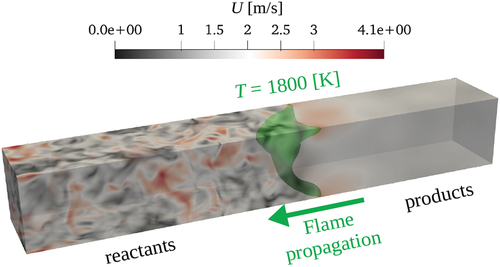
, in Appendix A. displays the velocity magnitude of the turbulent field in the square prism after one chemical timescale, where the isosurface of
= 1800 K (as a representation of the flame front) is marked with green color.
Figure 1. Velocity magnitude after one chemical timescale in the considered square prism for the 3D turbulent numerical simulation. The = 1800 K isosurface is marked with green color.
Numerical solver and chemical mechanism
Here, the main solver for 1D simulations and 3D quasi-DNS is the reactingDNS solver in OpenFOAM. This solver is previously used for studying n-heptane/air laminar premixed flames in a low-temperature ignition regime (Zhong et al. Citation2020), spherical laminar premixed flames with intrinsic flame instability (Zhang et al. Citation2020), turbulent flames propagation and ignition (Zhong et al. Citation2018) and (Zhong et al. Citation2020), and ammonia/methane/air premixed laminar burner flames (Rocha et al. Citation2021). The reliability of OpenFOAM in conducting quasi-DNS is thoroughly discussed in (Zirwes et al. Citation2020). Moreover, the features of the recently modified and open-source DLBFoam (Tekgül et al. Citation2021), which enables fast reactive flow simulations by implementing analytical Jacobian and dynamic load balancing, is used. Details and validation of the DLBFoam is thoroughly provided in (Morev et al. Citation2022). Equations of mass, momentum, species, and energy conservation are solved with the compressible PIMPLE algorithm. For quasi-DNS, the second-order implicit backward Euler method and the cubic scheme are used for temporal and spatial discretizations, respectively. The mixture-averaged diffusion model is used in all numerical simulations to include non-unity Lewis number effects (Steinberg, Hamlington, and Zhao Citation2021). We note that laminar simulations are conducted using both the unstrained premixed flame model in Cantera and using OpenFOAM. However, since the results of the two solvers match well, only OpenFOAM results are presented.
The chemical kinetics mechanism developed by Stagni et al. (Citation2020), which contains 31 species and 203 reactions, is utilized in all numerical simulations. The performance of this mechanism for ammonia/hydrogen mixtures is thoroughly studied in (Shrestha et al. Citation2021). It is noteworthy that a large uncertainty in the calculation of the flame speed and NO formation using different developed chemical kinetic mechanisms is reported for ammonia and ammonia/hydrogen combustion, c.f. (Sabia et al. Citation2020; Valera-Medina et al. Citation2018). Nonetheless, Shrestha et al. (Citation2021) have shown that the chemical mechanism by Stagni et al. (Citation2020) provides a reasonable accuracy on the calculation of the laminar flame speed for various blends of ammonia/hydrogen around the stoichiometry. It is noteworthy that although the reported NOx levels in this work are subject to quantitative uncertainty, the trends in NO formation pathways are expected to be insensitive to the choice of the chemical mechanism. For further information, please refer to (da Rocha, Costa, and Bai Citation2019; Shrestha et al. Citation2021).
NO formation pathways
NO generation in ammonia flames is known to be mainly through the fuel pathways with a rapid increase in the reaction zone and a gradual decrease in the post-flame zone. This trend is opposite to that of hydrocarbon flames (such as methane), where the thermal pathway plays the most significant role in NO formation and therefore, there is a gradual NO increase in the post-flame zone (Correa Citation1993; Trisjono and Pitsch Citation2017). As such, although controlling flame temperature in hydrocarbon flames, e.g. through lean combustion, is of utmost importance to mitigate NOx, in ammonia flames (and when hydrogen is slightly added), burning the mixture under stoichiometric or slightly rich conditions is recommended (Elbaz et al. Citation2022; Kobayashi et al. Citation2019; Valera-Medina et al. Citation2018).
According to Lindstedt, Lockwood, and Selim (Citation1994), in ammonia oxidation, first, NH2 and NH form through the reaction of NH3 with OH, H, or O radicals. Then, NH2 and NH radicals may produce NO through two different pathways: (i) directly after reacting with O or O2 or (ii) through forming the intermediate species HNO, which eventually generates NO. Such a pathway containing either NH2 or NH leading to the direct formation of NO is called NH2 pathway in this work. However, NO formation through HNO intermediate species is called the HNO pathway. It is notable that HNO is typically the most important pathway toward NO formation in ammonia flames (Kobayashi et al. Citation2019). On the other hand, the so-called Zeldovich (thermal) pathway (Zeldovich Citation1946) becomes more important when hydrogen is added to ammonia (Lindstedt, Lockwood, and Selim Citation1994). The Zeldovich pathway includes (i) the reaction between atmospheric nitrogen and atomic oxygen or (ii) the reaction of N atom with O and OH. In hydrocarbon (such as methane) flames, the Zeldovich pathway is thermal since N2 dissociates to the N atom only at temperatures above 1800 K. However, in ammonia-containing flames, the Zeldovich pathway is not necessarily thermal since the N atom can be formed by H abstraction (non-thermal) from NH3/NH2/NH or by N2 dissociation (thermal like in hydrocarbon flames). The extended Zeldovich pathway has been defined earlier in ammonia flames by Lindstedt, Lockwood, and Selim (Citation1994) and Kobayashi et al. (Citation2019). Besides NO2 and N2O, which may form NO in ammonia and ammonia/hydrogen flames, the NNH intermediate species which forms by the combination of NH2 radicals and its consequent dissociation may also lead to N2 or NO formation when reacted with the O radical. Here, the reactions leading to NO formation through N2 or NNH are classified as the N2 pathway. It should be mentioned that N2 is a final product in ammonia flames and it is not an intermediate in forming NO. However, the pathways defined in the following classification in this work involve both NO production and consumption and for instance here, the N2 pathway is defined as an “NO reducing pathway.”
Considering the above-mentioned information and the details available in the literature on NO formation in laminar ammonia or ammonia/hydrogen flames (Hayakawa et al. Citation2015; Kobayashi et al. Citation2019; Lindstedt, Lockwood, and Selim Citation1994), in the present work, chemical reaction pathways for NO formation (called NO pathways) are defined as follows. Six pathways are considered herein, namely, N2, NH2, N2O, Zeldovich, HNO, and NO2. To obtain the relevant reactions in each pathway, first, all the reactions containing NO in the utilized chemical mechanism are considered (41 reactions contributing to NO formation). Second, their importance in NO formation under the considered laminar flame conditions in this work is evaluated, and third, the most important reactions in each pathway are selected. Details of the reactions considered in each pathway are presented in . Our evaluation shows that adding NO production rates of the reactions in provides a very close estimate of the total NO production rate in the considered case studies. Therefore, we limit our following NO formation analyses to these reactions only.
Table 2. Selected reactions in NO formation pathways. The red box denotes reactions of the DeNOx process.
The DeNOx process, which typically initiates within intermediate temperatures in the presence of O2, reduces NOx by consuming NO (and NO2) in reaction with NHi (NH2, NH) radicals (Lyon Citation1975). Within this process, NNH and N2O are formed which eventually lead to N2 formation. The reactions that belong to the DeNOx process in the selected reactions in this work are shown inside a red box in . These reactions belong to the N2 and N2O pathways and it is expected that they typically consume NO; i.e. negative NO production rates. This point will be further elaborated in the results section.
The utilized technique in this work for the investigation of NO formation in ammonia/hydrogen premixed flames is similar to that used earlier by Karimkashi (Citation2017) for methane/air flames. This technique enables understanding the contribution of each pathway in NO formation along the flame brush in the reaction progress variable space. Particularly, NO rate of production (rop) through each pathway, which is the sum of NO production rates of the reactions in that pathway, is computed in the progress variable space. Such a technique can provide a deep insight into the role of hydrogen addition and turbulence on the variations of each pathway in the reaction layer and post-flame zones, which is its main advantage over the available techniques in the literature for ammonia/hydrogen flames, such as the oxidation pathway flow analysis (Miller et al. Citation1983; Netzer et al. Citation2021; Shrestha et al. Citation2021) and reaction rates analysis in 0D homogeneous reactors (da Rocha, Costa, and Bai Citation2019). According to Driscoll et al. (Citation2020) and the findings of Trisjono and Pitsch (Citation2017) and Karimkashi (Citation2017) for methane/air flames, high turbulence intensity may change the importance of NO formation pathways in different zones of a premixed flame compared to its corresponding laminar flame.
Results and discussions
H2 enrichment effects on NO formation under laminar condition
In the present work, C denotes the reaction progress variable, which is defined based on local temperature () as
presents mass fractions of three important species in NOx formation, i.e. NO and NO2, as well as N2O in the progress variable space for unstrained laminar premixed flames of = 0, 0.4, and 0.6 using both Cantera and OpenFOAM solvers. The observed trends using both solvers match fairly, noting the different discretization methods and grid resolutions in Cantera and OpenFOAM. The concentration of NO2 is two orders of magnitude smaller than NO and N2O in all cases; hence, negligible. It is noted that by increasing
, NO and N2O concentrations increase while the relative importance of N2O decreases compared to NO, which is consistent with the observations in (Kobayashi et al. Citation2019).
Figure 2. NO, NO2 and N2O concentrations in laminar flames at different in the progress variable space (NO2 is multiplied by 100). The dashed and solid lines correspond to the OpenFOAM and Cantera results, respectively.
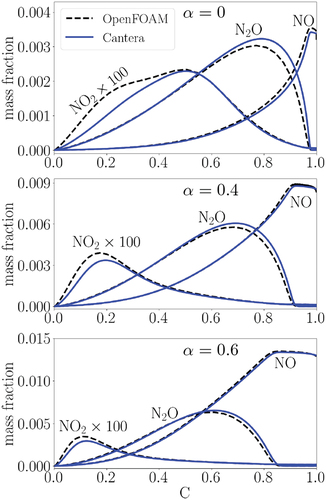
Bearing in mind that N2O is also an important species for NOx evaluations in stoichiometric flames, we shift our focus to NO formation hereafter due to its relative prevalence. Two important observations are made regarding to NO formation with increasing in : first, NO depicts an extended post-flame area in the progress variable space, and second, mass fraction values of NO increases. The reported trends are justified in the following discussion. We note that in the following, although only the OpenFOAM results are presented, the Cantera results are also analyzed by the authors and found to provide consistent conclusions for the considered laminar flames in this study.
portrays the rate of production (rop) of the NO formation pathways as previously defined in at different . Positive (negative) rop represents NO production (consumption).
Figure 3. The production rates (rop) of NO formation pathways for laminar flames at different in the progress variable space. The solid black line denotes the total NO production rate from all the 41 reactions containing NO in the utilized chemical mechanism.
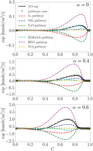
First, it is observed that the sum of rop in all the considered pathways (the triangle symbol) matches well with the total NO rop (the solid line) at different . This observation confirms that the considered reactions in the defined pathways can well capture the NO formation mechanism under the initial conditions considered in this study. Second, consistent with the observation in , with increasing
, the peak values of all pathways shift toward smaller progress variable values leading to a larger NO area in the post-flame zone. This observation is a direct result of the progress variable definition, see EquationEquation (2)
(2)
(2) , which is based on temperature. By increasing
, adiabatic flame temperature increases (c.f. ), meaning that an identical progress variable at a larger (smaller)
corresponds to a higher (lower) local temperature. Therefore, at higher
, reactions are activated at smaller progress variable values and the post-flame zone of NO is extended. Third, all the production rates get larger with the increase of
due to (i) higher local temperatures leading to larger activation energy and (ii) higher mass fractions of O2 and H2 at higher
(c.f. ), which will be further discussed in the following. Fourth, at different
, the HNO and N2O pathways have the primary roles in NO formation and consumption, respectively, while the NH2 and N2 pathways have the secondary roles. It is observed that the contribution of the NH2 pathway in NO formation becomes stronger with increasing
. Also, it is noteworthy that the N2O and N2 pathways, which have the most significant role in NO reduction, are classified as the DeNOx process, c.f. . Fifth, the Zeldovich pathway becomes less important as
increases and its contribution switches from positive (NO production) at
= 0 to negative (NO consumption) at
= 0.6. These results indicate that in ammonia/hydrogen/air flames, the Zeldovich pathway is insignificant in NO formation, which is in contrast to the trend in hydrocarbon flames, as consistent with the findings in the literature such as (Netzer et al. Citation2021).
NO production rates of each reaction in the defined pathways (c.f. ) are provided in for different at C = 0.7. The progress variable C = 0.7 is chosen for the sake of representation in the reaction zone, which is around the maximum heat release rate at different
. However, we note that samplings at C = 0.5 and 0.9 provide similar trends, qualitatively (not shown).
Figure 4. Production rates (rop) of the considered reactions in the NO formation pathways for the laminar flames at different captured at C = 0.7.
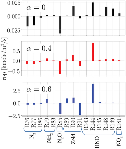
It is observed that at = 0, R76 and R77 (N2 pathway), R85 (N2O pathway), R90 (Zeldovich pathway), R144, R148, and R149 (HNO pathway), and R181 (NO2 pathway) constitute the most important contributions in NO formation. With increasing
, this trend changes such that N2 and NO2 pathways lose their relative importance, while in the Zeldovich pathway, R91 gains more importance, and in the HNO pathway, R144 gains dominance over R148 and R149. In particular, it is observed that at
= 0.4 and 0.6, although the individual reactions of the Zeldovich pathway are important, they cancel each other with opposite contributions in NO formation (at
= 0.4,
and at
= 0.6,
). This observation explains the minor role of the Zeldovich pathway in NO formation at
= 0.4 and 0.6, despite the relative importance of the individual reactions in this pathway. As an important takeaway for the following turbulent premixed flame analysis, at
= 0.4, two reactions (pathways) have the most significant contribution to NO formation: R85 (N2O pathway) and R144 (HNO pathway).
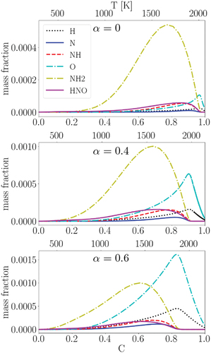
displays the mass fractions of several intermediate species, which are important in the activation of the reactions discussed in , at different in the progress variable space for the studied unstrained laminar premixed flames. The top x-axis depicts the profiles in the temperature space: an identical progress variable at a larger (smaller)
corresponds to a higher (lower) local temperature. At
= 0, NH2 is significantly abundant compared to other displayed species, while with increasing
, concentrations of the O and H radicals increase such that at
= 0.6, the O radical is the most dominant species. This observation explains the important roles of R76 and R77 in the N2 pathway and R149 in the HNO pathway at
= 0, where abundant availability of NH2 reinforces these reactions (c.f. ). The main reason for the abundant availability of NH2 at
= 0 is the initially higher concentration of NH3 in the reactants premixed mixture compared to the cases with higher
(c.f. ). On the other hand, at higher
, the higher concentrations of H2 and O2 in the reactants premixed mixture may lead to abundant H and O radicals, which can reinforce R144 (HNO pathway) and R91 (Zeldovich pathway) while suppressing the NH2-dependent reactions (R76, R77, and R149). One main reason for the activation of the Zeldovich pathway reactions with increasing
is the higher adiabatic flame temperature with increasing
. However, since the Zeldovich pathway has a very small contribution to NO formation at various
(because they cancel out each other, c.f. ), we do not further explore the importance of these reactions in the NO formation process.
Figure 5. Selected species and radicals mass fractions in the progress variable space for the laminar flames at different .
Relevance to practical combustion devices
In this section, we briefly discuss the relevance of the considered initial conditions in this work to practical combustion devices and we highlight the effect of elevated pressure and temperature on NO formation pathways under the laminar condition.
In this work, the considered initial conditions are stoichiometric, standard temperature and atmospheric pressure. In opposite to hydrocarbon fuels, in ammonia flames NO formation is smaller around stoichiometry and slightly rich conditions compared to lean conditions as previously discussed by different researchers such as (Kobayashi et al. Citation2019). Moreover, while NOx levels in ammonia/hydrogen flames at ultra-lean conditions is comparable with that at stoichiometry, the laminar flame speed is very low for those flames at ultra-lean conditions, which limits their practical application. For instance, according to our calculations in Cantera using the same chemical mechanism used in this work, for ammonia/hydrogen flames at = 0.4, laminar flame speed is 6 times smaller when the equivalence ratio
= 0.5 compared to the stoichiometric condition. Therefore, ultra-lean conditions are also not preferable for ammonia/hydrogen flames with low hydrogen concentrations (e.g.
= 0.4) in the premixed mixture at standard temperature. On the other hand, although increasing temperature helps to increase the laminar flame speed, it leads to higher NOx levels. Therefore, using stoichiometric condition in this work is considered relevant to practical conditions, especially when
= 0 or 0.4.
Due to the high computational costs of the conducted 3D turbulent case study, presented in the following, considering high pressure conditions is not feasible herein. However, under laminar conditions, the production rates of NO formation pathways at standard and elevated pressure and temperature are compared in . Here, we have utilized Cantera and the same chemical mechanism used in this work. The left figure corresponds to what was earlier presented in (middle) at the standard condition while the right figure presents NO formation pathways rop at = 20 atm and
= 500 K. It is observed that although the quantitative values are subject to change at higher pressure and temperature, the qualitative trends of the pathways in the progress variable space are very similar. In particular, in both conditions, HNO is the most important pathway of NO production while N2 and N2O are the most consuming ones. Here, the NO2 pathway is not shown due to its small contribution to NO formation. Although the other two pathways, NH2 and Zeldovich, have variations with temperature and pressure, their contribution to NO formation is marginal. Therefore, despite the fact that the standard condition is considered in the following 3D turbulent case study, the general understandings obtained by the provided results might be still relevant to practical conditions.
Figure 6. The production rates (rop) of NO formation pathways for laminar flames with = 0.4 at standard and elevated initial pressure and temperature in the progress variable space.

With the attained knowledge on NO pathways and reactions under laminar conditions in this section, next, we study effects of turbulence on NO formation at = 0.4. Understanding NO formation pathways and their interaction with the blending ratio of ammonia/hydrogen and with turbulence is important to find solutions for NOx mitigation in combustion devices. In particular for ammonia/hydrogen flames, since NO mainly forms within or in the immediate vicinity of the reaction zone and due to the high preferential diffusion of H2 to the hot regions of flame, it is important to analyze NO production/consumption across the flame.
We note that the authors have also studied three other decaying turbulent flames at = 0,
= 0.4, and
= 0.6 under a similar normalized integral length scale (
= 3.5) but at a smaller normalized turbulence intensity (
= 4). However, since effects of turbulence on changing NO pathways in those cases compared to their laminar counterparts are not far different from the one at a higher turbulence intensity presented in the following, we do not present those cases for brevity. However, the data of those quasi-DNS cases as well as the one presented herein will be available to interested readers upon request.
An overview of the decaying turbulent premixed flame
The main intention of this section is to provide an overall picture of the studied turbulent flame at = 0.4, presented and discussed in the remainder of this paper. presents the cutplane contours of temperature (
), enstrophy (in the logarithmic scale), heat release rate (
), NH mass fraction, NH3 mass fraction and H2 mass fraction for the studied turbulent case at one
(around 4.5 eddy turn-over time). Isolines of C = 0.1, 0.3, 0.5, 0.7, and 0.9 are superimposed on the temperature and enstrophy contours in a color spectrum of black to light blue, respectively. Enstrophy is a representative of energy containing eddies in the flow field and it is observed that it is stronger on the reactants side while it starts to further dissipate toward the reaction zone layer and strongly damped on the products side, as expected. Therefore, under such turbulence within the thin reaction zones combustion region of the Borghi-Peters regime diagram, the preheat layer is broadened compared to the laminar condition such that the C = 0.1 to 0.3 isolines are departed and disrupted leading to temperature fluctuations within the preheat layer. However, the reaction zone layer seems to remain relatively intact compared to the laminar flame since the heat release rate and NH (which is a marker of the heat release rate in ammonia flames) depict small variations in magnitude along the reaction zone layer.
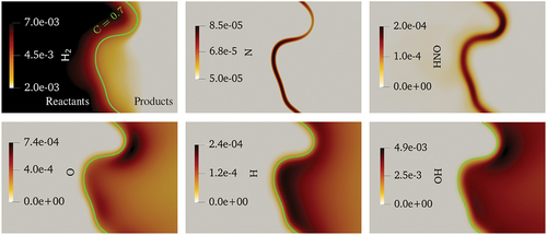
Figure 7. Cutplanes of (a) temperature, (b) enstrophy (logarithmic scale), (c) heat release rate, (d) NH mass fraction, (e) NH3 mass fraction, and (f) H2 mass fraction at one chemistry time-scale ( 4.5 eddy turn-over time) in the turbulent case study. The isolines on top of the temperature and enstrophy contours represent C = 0.1, 0.3, 0.5, 0.7, and 0.9 in a color spectrum of black to light blue, respectively.
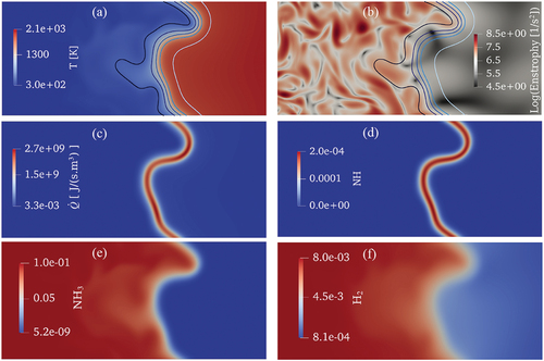
Moreover, the observed fluctuations of NH3 and H2 mass fractions in the preheat zone of the premixed flame, could mainly attribute to the strong effect of turbulence and preferential diffusion of H2 from the reactants side toward the hot regions. It should be noted that the scope of this paper is not to investigate effects of these events on flame dynamics. However, in the following, more discussions will be provided on effects of turbulence and H2 preferential diffusion on NO formation along the flame.
Turbulence effects on NO formation across the flame brush
displays NO mass fraction in the simulated 3D turbulent premixed flame at one (scatter data and conditional mean) and the 1D laminar case at
= 0.4 in the progress variable space. All the data are normalized by the maximum value of NO mass fraction in the laminar case at
= 0.4,
. It is observed that under the turbulent condition, NO distribution follows the depicted trend of the laminar flame with expected fluctuations in the scatter data and slightly smaller mass fractions in the conditional mean at the post-flame zone. This plot is repeated at three other simulation time instances, earlier and later than one
, in Appendix A.
Figure 8. (a): Distribution of NO mass fraction in the 3D turbulent flame (scatter and conditional mean) at one compared to the laminar flame. (b): Conditional mean of the production rates (rop) of NO formation pathways in the 3D turbulent flame at one
(solid) compared to the laminar flame (dashed).
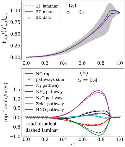
Similarly, shows the rop mean values of the NO pathways in the turbulent case at one (solid lines) compared to the 1D results (dashed lines). Here, the NO2 pathway is ignored due to its negligible contribution to NO formation under laminar and turbulent conditions at
= 0.4 (c.f. ). It is observed that the total NO production rate (the black solid line) and the sum of the pathways rop (the triangle symbol) match well, meaning that the chosen pathways can well capture the NO formation mechanism in the 3D turbulent case study. Despite the higher absolute values of rop for different pathways in the turbulent case compared with those of the unstrained laminar condition at
= 0.4, turbulence does not switch the pathways sign or trend. Thereby, we do not further explore the pathways across the flame brush since the analysis leads to similar results provided in Section 3.1. for the laminar flame at
= 0.4. For instance, our analysis shows that the production rates of the reactions follow a similar trend shown and discussed in (not shown here for brevity). It is noteworthy that with a higher turbulence intensity, there are more chances of significant changes in the NO pathways compared to the laminar condition, which is beyond the scope and available resources of this work. In the following, we shift our focus to the effect of turbulence on NO formation inside the reaction zone.
Turbulence effects on NO formation within the reaction zone
In the present work, consistent with the definition provided in various studies such as those in (Han and Huh Citation2008; Inanc, Kempf, and Chakraborty Citation2022), flame front curvature is defined as
where =
is the normal vector on a specified progress variable (
) pointing toward the reactants. In this convention, negative (positive) flame front curvature corresponds to the regions concave (convex) toward the reactants. Hereafter, we normalize the curvature by the laminar flame thickness at
= 0.4 (c.f. ).
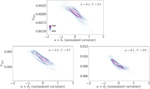
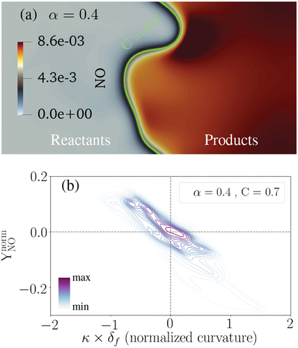
illustrates the contour of NO mass fraction on a 2D cutplane of the 3D data, where the green solid line represents the C = 0.7 isoline. Moreover, in , normalized NO mass fraction relative to the normalized curvature at C = 0.7 is depicted based on the 3D data in a joint probability density function (pdf) plot. In the presented joint pdfs, darker (lighter) background lines are of more (less) importance since they represent a higher (lower) probability. In the following joint pdf plots, scalar is normalized with respect to its laminar flame counterpart (
= 0.4, C = 0.7) following EquationEquation (4)
(4)
(4)
Figure 9. (a): NO mass fraction on a selected cutplane at one . The green solid line presents the C = 0.7 isoline. (b): The joint pdf plot of normalized NO mass fraction with normalized curvature at C = 0.7 and after one
.
wherein and
are the value and absolute value of
in turbulent and laminar conditions, respectively. It is worth mentioning that the choice of the observation time between 0.5–2.0
is not expected to affect the qualitative trends as shown and discussed in Appendix A. Moreover, the selected progress variable C = 0.7 does not influence the trends observed in this and the following figures while the quantitative values might change. For instance, the joint pdf in is re-plotted at C = 0.5 and C = 0.9 in Appendix B, where it is shown that the qualitative trends in the joint pdfs are independent of the choice of C value. This point is valid for the following joint pdfs shown in this work, which are only presented at C = 0.7 for brevity.
The subplots in elaborate that NO formation is enhanced at the negative curvature regions of the flame front (concave toward the reactants) compared to the positive curvature regions. A similar trend was recently observed using 2D DNS in (Netzer et al. Citation2021) for stoichiometric NH3/H2/N2/air wrinkled laminar flames. Here, it is observed that NO mass fraction increases (drops) around 10–15% at negative (positive) curvature regions compared to the laminar condition. In order to understand the reason behind the observed trend, the relevant reactions and species are studied in the following.
As earlier discussed, N2O and HNO are the most important pathways toward NO formation in the studied turbulent premixed flame, while the N2 pathway is also an important contributor. Therefore, to better understand the underlying reason behind the negative correlation of NO mass fraction with curvature, the production rates of N2O, HNO, and N2 pathways normalized by their laminar counterparts at = 0.4 and C = 0.7, following EquationEquation (4)
(4)
(4) , are shown in a joint pdf plot with normalized curvature in , (b), (c), respectively. The right y-axes show the real values of rop.
Figure 10. The joint pdf plots of normalized and real production rates (rop) for (a) N2O, (b) HNO, (c) N2, and (d) Zeldovich pathways with normalized curvature at C = 0.7 and after one .
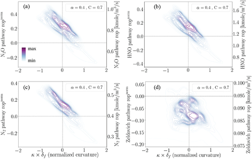
First, it is observed that these three pathways have a strong negative correlation with normalized curvature. This observation explains the main reason for the negative correlation of NO mass fraction with curvature in . Among all the shown pathways, only the Zeldovich pathway, i.e. , does not demonstrate any correlation with normalized curvature. However, we remind that R90 and R91 cancel out each other leading to a negligible Zeldovich pathway contribution to NO formation. Second, it is observed from that compared to the unstrained laminar condition, the production rates of N2O and HNO pathways are increased around 30–40% at the negative curvature regions and they are even modestly increased at the slightly positive curvature regions. Hereafter, we mainly focus on the two most important pathways toward NO formation in this study: N2O and HNO, bearing in mind that the N2 pathway is of the secondary importance.
According to the observation under laminar conditions, R85 and R144 are the main contributors to the N2O and HNO pathways, respectively. Our investigation reveals that these two reactions are still dominant in the studied turbulent premixed flame. NO production rates of R85 and R144, and the total NO production rate are demonstrated in the cutplane countour plots in (top row). The green solid line represents the C = 0.7 isoline.
Figure 11. NO production rates of R85 and R144 and total NO production rate at one , where the green solid line presents the C = 0.7 isoline (top row). The joint pdf plots of normalized NO production rates through R85 and R144 with normalized curvature at C = 0.7 after one
(bottom row).
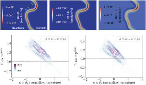
It is observed that both R85 and R144 have higher reaction rates around the negative curvature regions similar to the trend observed for the N2O and HNO pathways. Consistently, higher NO production rates are observed at the negative curvature regions. The bottom row in displays the joint pdf plots of normalized rop (following EquationEquation (4))(4)
(4) for these two reactions with normalized curvature using the 3D data. It is observed that compared to the unstrained laminar condition, the production rate of these two reactions have increased mainly at the negative curvature regions.
In order to better understand the reason behind the reinforcement of N2O and HNO pathways leading to the enhancement of NO formation at the negative curvature regions of the flame front, effects of molecular and atomic hydrogen preferential diffusion are evaluated in the following.
Effects of hydrogen preferential diffusion on NO formation
Following (Peters Citation2000; Song, Hernández-Pérez, and Im Citation2022), in this study the diffusion flux for species is defined as
where and
=
represent the diffusion velocity and mixture-averaged diffusion coefficient of species
, respectively, wherein
,
, and
are the mole fraction of species
, the mass fraction of species
, and the binary diffusion coefficient between species
and
, respectively. Here,
is the density.
displays the scatter plots and mean profiles of the diffusion fluxes for H2 and H species, normalized following EquationEquation (4)(4)
(4) , versus normalized curvature at a specific progress variable C = 0.7. It should be noted that a similar trend is observed for smaller (C = 0.5) and larger (C = 0.9) progress variables (not shown).
Figure 12. Scatter and conditional mean of the diffusion fluxes for (a) H2 and (b) H in the 3D turbulent flame normalized by the corresponding value of the laminar case versus normalized curvature at C = 0.7 after one .
This result indicates the enhanced (reduced) diffusion of H2 in the positive (negative) curvature regions of the studied turbulent flame compared to the corresponding laminar conditions. In particular, H2 diffuses from the reactants side to the positive curvature regions of the reaction zone while diffusing away from the negative curvature regions due to the so-called ”open tip” phenomenon. This well-known phenomenon is also observed and reported in the literature for lean H2 and H2-containing premixed flames (Lee et al. Citation2021; Netzer et al. Citation2021; Rieth et al. Citation2021; Wiseman et al. Citation2021). It is noteworthy that despite the stoichiometric condition here, H2 is locally lean since NH3 is also present in the reactants mixture. The H radical demonstrates an opposite trend in this figure, i.e. diffusing away from the positive curvature regions of the reaction zone, which is consistent with the findings in (Rieth et al. Citation2021). It is noteworthy that despite the high preferential diffusion of the H radical, it is simultaneously produced and consumed in the reaction zone and hence, the H radical is abundant in both positive and negative curvature regions.
depicts the mass fraction of H2 versus normalized curvature at C = 0.7. Consistent with the above discussion, it is observed that H2 has a higher concentration at the positive curvature regions compared to the negative ones. Therefore, according to , H2 consumption rate is found to be higher at the positive curvature regions compared to the negative curvature regions (note that the rate of H2 production is shown and negative values depict consumption). Our investigation on all the reactions containing H2 in the utilized chemical mechanism (23 reactions in total) reveals that H2 is mainly consumed through two reactions and that H2 consumption rates by these two reactions have strong positive correlations with curvature, which are:
Figure 13. Scatter and conditional mean profiles of (a) the normalized H2 mass fraction and (b) normalized total H2 consumption rate versus normalized curvature at C = 0.7 as well as H2 consumption rate through R2 (c) and R3 (d) versus normalized curvature at C = 0.7 after one .
H2 + O H + OH (R2)
and
H2 + OH H + H2O (R3).
The scatter and mean profiles of the H2 consumption rate through R2 and R3 against normalized curvature at C = 0.7 are provided in , respectively. It is found that the consumption rate of H2 through these two reactions is higher at the positive curvature regions compared to the negative ones. Therefore, it is deduced that the main process following the preferential diffusion of H2 to the positive curvature regions is a stronger consumption of H2 through R2 and R3 at the positive curvature regions compared to the negative ones. Considering that H2 reacts with O and OH radicals through R2 and R3, this process can lead to the depletion of O and OH radicals at the positive curvature regions and their relative abundance at the negative curvature regions (although we note that OH is simultaneously consumed by R3 and produced by R2).
It is noteworthy that except R2 and R3, discussed above, R144 (shown earlier in ) and four other reactions depict significant H2 production in both negative and positive curvature regions:
NH2 + H NH + H2 (R25),
NH3 + H NH2 + H2 (R26),
NH + H N + H2 (R78),
N2H2 + H NNH + H2 (R113).
However, since these five reactions do not consume (but produce) H2, their analysis is not presented herein. Similar to R144, shown earlier in , all of these reactions show a negative correlation between the H2 production and curvature by consuming the abundant H radical in reaction with ammonia (NH3) or its dissociated radicals (NH2, NH and N2H2).
For the sake of completeness, contour plots of some important intermediate species and radicals are displayed in . As it is observed, H2 is abundant at the positive curvature region while O and OH are deficient in that region compared to the negative curvature region. This trend can be explained by H2 consumption rates through R2 and R3 as earlier shown in . The comparatively higher O and OH radicals at the negative curvature region compared to the positive one and their reaction with the available H and N radicals may lead to the stronger formation of NO and HNO species at the negative curvature region. On the other hand, despite the availability of H and N radicals at the positive curvature regions, deficiency of O and OH radicals leads to smaller concentrations of NO and HNO species compared to those at the negative curvature regions. This phenomenon can be observed in , where high concentrations of HNO and NO at the negative curvature region are noticed. It should be mentioned that the species like N and HNO are formed in a narrow region within the reaction zone and the isoline (C = 0.7) is not displayed on top of these two plots for a better visualization.
Figure 14. The mass fractions of important intermediate species and H2 in the turbulent premixed flame at one . The green solid line indicates the C = 0.7 isoline (not shown on top of the N and HNO contour plots for better visualization purposes).
Finally, as a brief summary, the relatively higher NO concentration at the negative curvature regions can be explained by two processes, which are both related to the high preferential diffusion of H2 to the positive curvature region. First, due to the abundance of H2 at the positive curvature region, R144 plays an important role to consume NO in that region. Second, due to the abundance of H2 at the positive curvature region (compared to the negative curvature region), R2 and R3 consume the available O and OH in reaction with H2, leading to the deficiency of those radicals, which are essential for HNO and NO formation. These processes eventually lead to the relatively lower (higher) NO formation in the regions convex (concave) toward the reactants (c.f. ).
Conclusions
Effects of hydrogen enrichment and turbulence on NO formation in planar premixed ammonia flames with reactants at 298 K, atmospheric pressure, and stoichiometric conditions were studied using 1D and 3D simulations with detailed chemistry. The most important reactions and pathways of NO formation were identified. Below is a summary of the main findings.
In 1D, NO formation enhances around 3 times by increasing the hydrogen ratio in reactants (
) from 0 to 0.6. The main reason is the higher availability of H and O radicals in the reaction zone as well as the higher flame temperature leading to the enhanced reaction rates with increasing
At different
In the 3D qausi-DNS, in the thin reaction zones region (
The main reason for lower (higher) NO formation in the regions convex (concave) toward the reactants is found to be the preferential diffusion of H2 to the positive curvature regions. This process leads to (i) more consumption of NO through R144 and (ii) depletion of O and OH radicals in the regions convex toward the reactants leading to weaker NO and HNO formation and consequently, smaller contributions of the HNO pathway toward NO formation.
Acknowledgements
We acknowledge the Academy of Finland (grant numbers 332784, 318024 and 332835) for financially supporting this work and CSC (the Finnish IT Center for Science) for providing the computational resources.
Disclosure statement
No potential conflict of interest was reported by the authors.
Additional information
Funding
References
- Aspden, A. J., M. S. Day, and J. B. Bell. 2011. Turbulence–flame interactions in lean premixed hydrogen: Transition to the distributed burning regime. J. Fluid Mech. 680:287–320. doi:10.1017/jfm.2011.164.
- Bell, J. B., M. S. Day, and M. J. Lijewski. 2013. Simulation of nitrogen emissions in a premixed hydrogen flame stabilized on a low swirl burner. Proc. Combust. Inst. 34 (1):1173–82. doi:10.1016/j.proci.2012.07.046.
- Berger, L., A. Attili, and H. Pitsch. 2022. Synergistic interactions of thermodiffusive instabilities and turbulence in lean hydrogen flames. Combust. Flame 244:112254. doi:10.1016/j.combustflame.2022.112254.
- Bioche, K., L. Bricteux, A. Bertolino, A. Parente, and J. Blondeau. 2021. Large Eddy Simulation of rich ammonia/hydrogen/air combustion in a gas turbine burner. Int. J. Hydrogen Energy 46 (79):39548–62. doi:10.1016/j.ijhydene.2021.09.164.
- Chakraborty, N., and R. S. Cant. 2009. Effects of Lewis number on turbulent scalar transport and its modelling in turbulent premixed flames. Combust. Flame 156 (7):1427–44. doi:10.1016/j.combustflame.2009.03.010.
- Chakraborty, N., E. R. Hawkes, J. H. Chen, and R. S. Cant. 2008. The effects of strain rate and curvature on surface density function transport in turbulent premixed methane–air and hydrogen–air flames: A comparative study. Combust. Flame 154 (1–2):259–80. doi:10.1016/j.combustflame.2008.03.015.
- Comotti, M., and S. Frigo. 2015. Hydrogen generation system for ammonia–hydrogen fuelled internal combustion engines. Int. J. Hydrogen Energy 40 (33):10673–86. doi:10.1016/j.ijhydene.2015.06.080.
- Correa, S. M. 1993. A review of NOx formation under gas-turbine combustion conditions. Combust. Sci. Technol. 87 (1–6):329–62. doi:10.1080/00102209208947221.
- Dai, L., S. Gersen, P. Glarborg, H. Levinsky, and A. Mokhov. 2020. Experimental and numerical analysis of the autoignition behavior of NH3 and NH3/H2 mixtures at high pressure. Combust. Flame 215:134–44. doi:10.1016/j.combustflame.2020.01.023.
- da Rocha, R. C., M. Costa, and X. S. Bai. 2019. Chemical kinetic modelling of ammonia/hydrogen/air ignition, premixed flame propagation and NO emission. Fuel 246:24–33. doi:10.1016/j.fuel.2019.02.102.
- Day, M. S., J. B. Bell, X. Gao, and P. Glarborg. 2011. Numerical simulation of nitrogen oxide formation in lean premixed turbulent H2/O2/N2 flames. Proc. Combust. Inst. 33 (1):1591–99. doi:10.1016/j.proci.2010.06.128.
- Dreizler, A., H. Pitsch, V. Scherer, C. Schulz, and J. Janicka. 2021. The role of combustion science and technology in low and zero impact energy transformation processes. Appl. Energy Combust. Sci 7:100040. doi:10.1016/j.jaecs.2021.100040.
- Driscoll, J. F., J. H. Chen, A. W. Skiba, C. D. Carter, E. R. Hawkes, and H. Wang. 2020. Premixed flames subjected to extreme turbulence: Some questions and recent answers. Prog. Energy Combust. Sci. 76:100802. doi:10.1016/j.pecs.2019.100802.
- Duynslaegher, C., H. Jeanmart, and J. Vandooren. 2009. Flame structure studies of premixed ammonia/hydrogen/oxygen/argon flames: Experimental and numerical investigation. Proc. Combust. Inst. 32 (1):1277–84. doi:10.1016/j.proci.2008.06.036.
- Elbaz, A. M., S. Wang, T. F. Guiberti, and W. L. Roberts. 2022. Review on the recent advances on ammonia combustion from the fundamentals to the applications. Fuel Commun. 10:100053. doi:10.1016/j.jfueco.2022.100053.
- Fenimore, C. P., and G. W. Jones. 1961. Oxidation of ammonia in flames. J. Phys. Chem. 65 (2):298–303. doi:10.1021/j100820a027.
- Frigo, S., and R. Gentili. 2013. Analysis of the behaviour of a 4-stroke Si engine fuelled with ammonia and hydrogen. Int. J. Hydrogen Energy 38 (3):1607–15. doi:10.1016/j.ijhydene.2012.10.114.
- Han, I., and K. Y. Huh. 2008. Roles of displacement speed on evolution of flame surface density for different turbulent intensities and Lewis numbers in turbulent premixed combustion. Combust. Flame 152 (1–2):194–205. doi:10.1016/j.combustflame.2007.10.003.
- Hawkes, E. R., and J. H. Chen. 2004. Direct numerical simulation of hydrogen-enriched lean pre- mixed methane–air flames. Combust. Flame 138 (3):242–58. doi:10.1016/j.combustflame.2004.04.010.
- Hayakawa, A., T. Goto, R. Mimoto, T. Kudo, and H. Kobayashi. 2015. NO formation/reduction mechanisms of ammonia/air premixed flames at various equivalence ratios and pressures. Mech. Eng. J 2 (1):14–00402. doi:10.1299/mej.14-00402.
- Haynes, B. S. 1977. Reactions of ammonia and nitric oxide in the burnt gases of fuel-rich hydrocarbon-air flames. Combust. Flame 28 (C):81–91. doi:10.1016/0010-2180(77)90010-4.
- He, X., B. Shu, D. Nascimento, K. Moshammer, M. Costa, and R. X. Fernandes. 2019. Auto- ignition kinetics of ammonia and ammonia/hydrogen mixtures at intermediate temperatures and high pressures. Combust. Flame 206:189–200. doi:10.1016/j.combustflame.2019.04.050.
- Inanc, E., A. Kempf, and N. Chakraborty. 2022. Scalar gradient and flame propagation statistics of a flame-resolved laboratory-scale turbulent stratified burner simulation. Combust. Flame 238:111917. doi:10.1016/j.combustflame.2021.111917.
- Ji, C., Z. Wang, D. Wang, R. Hou, T. Zhang, and S. Wang. 2021. Experimental and numerical study on premixed partially dissociated ammonia mixtures. Part I: Laminar burning velocity of NH3/H2/N2/air mixtures. Int. J. Hydrogen Energy 47 (6):4171–84. doi:10.1016/j.ijhydene.2021.10.269.
- Karimkashi, S. (2017), Direct numerical simulation studies of radiative heat transfer and pollutant emissions in combustion, Doctoral dissertation, Australia: UNSW Sydney. doi:10.26190/unsworks/20036
- Khateeb, A. A., T. F. Guiberti, G. Wang, W. R. Boyette, M. Younes, A. Jamal, and W. L. Roberts. 2021. Stability limits and NO emissions of premixed swirl ammonia-air flames enriched with hydrogen or methane at elevated pressures. Int. J. Hydrogen Energy 46 (21):11969–81. doi:10.1016/j.ijhydene.2021.01.036.
- Kobayashi, H., A. Hayakawa, K. D. A. Somarathne, and E. C. Okafor. 2019. Science and technology of ammonia combustion. Proc. Combust. Inst. 37 (1):109–33. doi:10.1016/j.proci.2018.09.029.
- Kurien, C., and M. Mittal. 2022. Review on the production and utilization of green ammonia as an alternate fuel in dual-fuel compression ignition engines. Energy Convers Manage. 251:114990. doi:10.1016/j.enconman.2021.114990.
- Lee, H. C., P. Dai, M. Wan, and A. N. Lipatnikov. 2021. Influence of molecular transport on burning rate and conditioned species concentrations in highly turbulent premixed flames. J. Fluid Mech 928. doi:10.1017/jfm.2021.794.
- Lee, H. C., P. Dai, M. Wan, and A. N. Lipatnikov. 2022. Lewis number and preferential diffusion effects in lean hydrogen–air highly turbulent flames. Phys. Fluids 34 (3):035131. doi:10.1063/5.0087426.
- Lee, J. H., S. I. Lee, and O. C. Kwon. 2010. Effects of ammonia substitution on hydrogen/air flame propagation and emissions. Int. J. Hydrogen Energy 35 (20):11332–41. doi:10.1016/j.ijhydene.2010.07.104.
- Lindstedt, R. P., F. C. Lockwood, and M. A. Selim. 1994. Detailed kinetic modelling of chemistry and temperature effects on ammonia oxidation. Combust. Sci. Technol. 99 (4–6):253–76. doi:10.1080/00102209408935436.
- Li, S., H. Zhou, L. Hou, and Z. Ren. 2017. An analytic model for the effects of nitrogen dilution and premixing characteristics on NOx formation in turbulent premixed hydrogen flames. Int. J. Hydrogen Energy 42 (10):7060–70. doi:10.1016/j.ijhydene.2016.12.092.
- Lyon, R. K. 1975 August 19. Method for the reduction of concentration of NO in combustion effluents using ammonia. U.S. Patent 3900554.
- Maclean, D. I., and H. G. Wagner. 1967. The structure of the reaction zones of ammonia-oxygen and hydrazine-decomposition flames. Proc. Combust. Inst. 11 (1):871–78. doi:10.1016/S0082-0784(67)80213-3.
- Mei, B., J. Zhang, X. Shi, Z. Xi, and Y. Li. 2021. Enhancement of ammonia combustion with partial fuel cracking strategy: Laminar flame propagation and kinetic modeling investigation of NH3/H2/N2/air mixtures up to 10 atm. Combust. Flame 231:111472. doi:10.1016/j.combustflame.2021.111472.
- Miller, J. A., and C. T. Bowman. 1989. Mechanism and modeling of nitrogen chemistry in combustion. Prog. Energy Combust. Sci. 15 (4):287–338. doi:10.1016/0360-1285(89)90017-8.
- Miller, J. A., M. C. Branch, and R. J. Kee. 1981. A chemical kinetic model for the selective reduction of nitric oxide by ammonia. Combust. Flame 43 (C):81–98. doi:10.1016/0010-2180(81)90008-0.
- Miller, J. A., M. D. Smooke, R. M. Green, and R. J. Kee. 1983. Kinetic modeling of the oxidation of ammonia in flames. Combust. Sci. Technol. 34 (1–6):149–76. doi:10.1080/00102208308923691.
- Mørch, C. S., A. Bjerre, M. P. Gøttrup, S. C. Sorenson, and J. Schramm. 2011. Ammonia/Hydrogen mixtures in an SI-engine: Engine performance and analysis of a proposed fuel system. Fuel 90 (2):854–64. doi:10.1016/j.fuel.2010.09.042.
- Morev, I., B. Tekgül, M. Gadalla, A. Shahanaghi, J. Kannan, S. Karimkashi, O. Kaario, and V. Vuorinen. 2022. Fast reactive flow simulations using analytical Jacobian and dynamic load balancing in OpenFOAM. Phys. Fluids 34 (2):021801. doi:10.1063/5.0077437.
- Morley, C. 1981. The mechanism of no formation from nitrogen compounds in hydrogen flames studied by laser fluorescence. Proc. Combust. Inst. 18 (1):23–32. doi:10.1016/S0082-0784(81)80007-0.
- Netzer, C., A. Ahmed, A. Gruber, and T. Løvås. 2021. Curvature effects on NO formation in wrinkled laminar ammonia/hydrogen/nitrogen-air premixed flames. Combust. Flame 232:111520. doi:10.1016/j.combustflame.2021.111520.
- Nozari, H., and A. Karabeyoglu. 2015. Numerical study of combustion characteristics of ammonia as a renewable fuel and establishment of reduced reaction mechanisms. Fuel 159:223–33. doi:10.1016/j.fuel.2015.06.075.
- Passot, T., and A. Pouquet. 1987. Numerical simulation of compressible homogeneous flows in the turbulent regime. J. Fluid Mech 181 (–1):441–66. doi:10.1017/S0022112087002167.
- Peters, N. (2000), ‘Turbulent Combustion’, Cambridge University Press. Cambridge .
- Philibert, C. (2017), Renewable Energy for Industry: From green energy to green materials and fuels, Technical report, IEA, Insight series.
- Pochet, M., V. Dias, B. Moreau, F. Foucher, H. Jeanmart, and F. Contino. 2019. Experimental and numerical study, under LTC conditions, of ammonia ignition delay with and without hydrogen addition. Proc. Combust. Inst. 37 (1):621–29. doi:10.1016/j.proci.2018.05.138.
- Rieth, M., A. Gruber, F. A. Williams, and J. H. Chen. 2021. Enhanced burning rates in hydrogen- enriched turbulent premixed flames by diffusion of molecular and atomic hydrogen. Combust. Flame 239:111740. doi:10.1016/j.combustflame.2021.111740.
- Rocha, R. C., S. Zhong, L. Xu, X. -S. Bai, M. Costa, X. Cai, H. Kim, C. Brackmann, Z. Li, and M. Aldén. 2021. Structure and laminar flame speed of an ammonia/methane/air premixed flame under varying pressure and equivalence ratio. Energy and Fuels 35 (9):7179–92. doi:10.1021/acs.energyfuels.0c03520.
- Saad, T., D. Cline, R. Stoll, and J. C. Sutherland. 2017. Scalable Tools for Generating Synthetic Isotropic Turbulence with Arbitrary Spectra. Aiaa J. 55 (1):327–31. doi:10.2514/1.J055230.
- Sabia, P., M. V. Manna, A. Cavaliere, R. Ragucci, and M. de Joannon. 2020. Ammonia oxidation features in a Jet Stirred Flow Reactor. The role of NH2 chemistry. Fuel 276:118054. doi:10.1016/j.fuel.2020.118054.
- Seery, D. J., and M. F. Zabielski. 1977. Mass spectrometer probing of a CO-NH3-O2 flame. Combust. Flame 28 (C):93–99. doi:10.1016/0010-2180(77)90011-6.
- Shrestha, K. P., C. Lhuillier, A. A. Barbosa, P. Brequigny, F. Contino, C. Mounaïm-Rousselle, L. Seidel, and F. Mauss. 2021. An experimental and modeling study of ammonia with enriched oxygen content and ammonia/hydrogen laminar flame speed at elevated pressure and temperature. Proc. Combust. Inst. 38 (2):2163–74. doi:10.1016/j.proci.2020.06.197.
- Skottene, M., and K. E. Rian. 2007. A study of NOx formation in hydrogen flames. Int. J. Hydrogen Energy 32 (15):3572–85. doi:10.1016/j.ijhydene.2007.02.038.
- Song, W., F. E. Hernández-Pérez, and H. G. Im. 2022. Diffusive effects of hydrogen on pressurized lean turbulent hydrogen-air premixed flames. Combust. Flame 246:112423. doi:10.1016/j.combustflame.2022.112423.
- Stagni, A., C. Cavallotti, S. Arunthanayothin, Y. Song, O. Herbinet, F. Battin-Leclerc, and T. Faravelli. 2020. An experimental, theoretical and kinetic-modeling study of the gas-phase oxidation of ammonia. React. Chem. Eng 5 (4):696–711. doi:10.1039/C9RE00429G.
- Steinberg, A. M., P. E. Hamlington, and X. Zhao. 2021. Structure and dynamics of highly turbulent premixed combustion. Prog. Energy Combust. Sci. 85:100900. doi:10.1016/j.pecs.2020.100900.
- Tamadonfar, P., S. Karimkashi, O. Kaario, and V. Vuorinen. 2022. Inner flame front structures and burning velocities of premixed turbulent planar ammonia/air and methane/air Flames. Flow Turbul. Combust. 109 (2):477–513. doi:10.1007/s10494-022-00341-x.
- Tekgül, B., P. Peltonen, H. Kahila, O. Kaario, and V. Vuorinen. 2021. Dlbfoam: An open-source dynamic load balancing model for fast reacting flow simulations in OpenFOAM. Comput. Phys. Commun. 267:108073. doi:10.1016/j.cpc.2021.108073.
- Trisjono, P., and H. Pitsch. 2017. A direct numerical simulation study on NO formation in lean premixed flames. Proc. Combust. Inst. 36 (2):2033–43. doi:10.1016/j.proci.2016.06.130.
- Valera-Medina, A., D. G. Pugh, P. Marsh, G. Bulat, and P. Bowen. 2017. Preliminary study on lean premixed combustion of ammonia-hydrogen for swirling gas turbine combustors. Int. J. Hydrogen Energy 42 (38):24495–503. doi:10.1016/j.ijhydene.2017.08.028.
- Valera-Medina, A., H. Xiao, M. Owen-Jones, W. I. David, and P. J. Bowen. 2018. Ammonia for power. Prog. Energy Combust. Sci. 69:63–102. doi:10.1016/j.pecs.2018.07.001.
- Wang, D., C. Ji, S. Wang, J. Yang, and Z. Wang. 2021. Numerical study of the premixed ammonia- hydrogen combustion under engine-relevant conditions. Int. J. Hydrogen Energy 46 (2):2667–83. doi:10.1016/j.ijhydene.2020.10.045.
- Wiseman, S., M. Rieth, A. Gruber, J. R. Dawson, and J. H. Chen. 2021. A comparison of the blow- out behavior of turbulent premixed ammonia/hydrogen/nitrogen-air and methane–air flames. Proc. Combust. Inst. 38 (2):2869–76. doi:10.1016/j.proci.2020.07.011.
- Wu, M. S., S. Kwon, J. F. Driscoll, and G. M. Faeth. 1990. Turbulent premixed hydrogen/air flames at high reynolds numbers. Combust. Sci. Technol. 73 (1–3):327–50. doi:10.1080/00102209008951655.
- Wu, M. S., S. Kwon, J. F. Driscoll, and G. M. Faeth. 1991. Preferential diffusion effects on the surface structure of turbulent premixed hydrogen/air flames. Combust. Sci. Technol. 78 (1–3):69–96. doi:10.1080/00102209108951741.
- Xiao, H., A. Valera-Medina, and P. J. Bowen. 2017. Modeling combustion of ammonia/hydrogen fuel blends under gas turbine conditions. Energy and Fuels 31 (8):8631–42. doi:10.1021/acs.energyfuels.7b00709.
- Yang, W., K. K. Ranga Dinesh, K. H. Luo, and D. Thevenin. 2022. Direct numerical simulation of turbulent premixed ammonia and ammonia-hydrogen combustion under engine-relevant conditions. Int. J. Hydrogen Energy 47 (20):11083–100. doi:10.1016/j.ijhydene.2022.01.142.
- Zeldovich, Y. B. 1946. The Oxidation of Nitrogen in Combustion and Explosions. Acta. Physicochim. 21:557–626.
- Zhang, X., S. P. Moosakutty, R. P. Rajan, M. Younes, and S. M. Sarathy. 2021. Combustion chemistry of ammonia/hydrogen mixtures: Jet-stirred reactor measurements and comprehensive kinetic modeling. Combust. Flame 234:111653. doi:10.1016/j.combustflame.2021.111653.
- Zhang, N., F. Zhang, S. Zhong, Z. Peng, J. Yu, H. Liu, and C. Xu. 2020. Numerical and theoretical investigation of ethanol/air flame instability. Combust. Theory Model. 24 (6):1108–29. doi:10.1080/13647830.2020.1820578.
- Zhong, S., F. Zhang, Q. Du, and Z. Peng. 2020. Characteristics of reactivity controlled combustion with n-heptane low temperature reforming products. Fuel 275:117980. doi:10.1016/j.fuel.2020.117980.
- Zhong, S., F. Zhang, M. Jangi, X. S. Bai, M. Yao, and Z. Peng. 2020. Structure and propagation of n-heptane/air premixed flame in low temperature ignition regime. Appl. Energy 275:115320. doi:10.1016/j.apenergy.2020.115320.
- Zhong, S., F. Zhang, Z. Peng, F. Bai, and Q. Du. 2018. Roles of CO2 and H2O in premixed turbulent oxy-fuel combustion. Fuel 234:1044–54. doi:10.1016/j.fuel.2018.07.135.
- Zirwes, T., F. Zhang, P. Habisreuther, M. Hansinger, H. Bockhorn, M. Pfitzner, and D. Trimis. 2020. Quasi-DNS dataset of a piloted flame with inhomogeneous inlet conditions. Flow Turbul. Combust. 104 (4):997–1027. doi:10.1007/s10494-019-00081-5.
Appendix A.
Statistics of NO mass fraction at different simulation time
In this appendix, the sensitivity of NO mass fraction results to the choice of observation time in the 3D turbulent flame simulation is explored. Four different time instances are selected for data analysis: 0.5 , 1.0
, 1.5
, and 2.0
, wherein
is the chemical timescale. In this simulation, each
is equivalent to 4.5 eddy turn-over time.
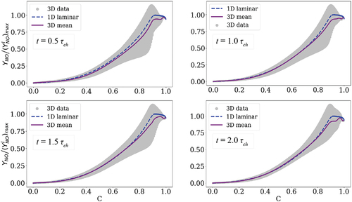
presents scattered and conditional mean 3D data of NO mass fraction in the progress variable space wherein the 1D laminar flame data is superimposed. This plot was provided in the main manuscript at 1.0 in . It is observed in that the choice of the observation time does not influence the global results. In particular, the scatter data does not vary significantly in time and the conditional mean profile is very similar to the 1D data profile although there are slight fluctuations at the post-flame zone.
Figure A1. Distribution of NO mass fraction in the 3D turbulent flame (scatter and conditional mean) compared to the laminar flame at four different time instances: 0.5 , 1.0
, 1.5
, and 2.0
.
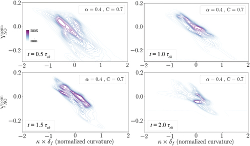
depicts joint pdfs of normalized NO mass fraction with normalized curvature when C = 0.7 at the four mentioned time instances. This plot was provided in the main manuscript at 1.0 in . The main observation here is that the negative correlation between the two parameters is not influenced with the observation time, i.e. NO formation is always enhanced at the negative curvature regions of the flame front compared to the positive curvature regions. Therefore, the qualitative trends are not affected when the observation time varies between 0.5-2.0
. However, as a remark, care should be taken in analyzing the data in decaying turbulence after 9 eddy turn-over time (
2.0
) since turbulence intensity and lengthscales might have varied, significantly.
Figure A2. The joint pdf plots of normalized NO mass fraction with normalized curvature captured at C = 0.7 at four different time instances: 0.5 , 1.0
, 1.5
, and 2.0
.
Appendix B.
Statistics of NO mass fraction at different progress variables
In this appendix, jont pdfs of NO mass fraction with normalized curvature at C = 0.5, 0.7, and 0.9 are presented in Figure B1. The y-axis is not normalized in contrast to the one in to present the real values of NO mass fractions in the turbulent case study. It is observed that the negative correlation between the two parameters holds at different chosen progress variables. Therefore, the choice of progress variable value in this analysis does not influence our main conclusions since the qualitative trends are unchanged. However, as expected, the absolute values of NO mass fraction increase at higher progress variables since higher C values mean higher temperature regions, c.f. .
Figure B1. The joint pdf plots of NO mass fraction with normalized curvature at C = 0.5, C = 0.7, and C = 0.9 after one chemical timescale (equivalent to 4.5 eddy turn-over time).