
 ?Mathematical formulae have been encoded as MathML and are displayed in this HTML version using MathJax in order to improve their display. Uncheck the box to turn MathJax off. This feature requires Javascript. Click on a formula to zoom.
ABSTRACT
This study is focused on finding optimised conditions for electrodeposition of NiP and NiP/SiC coatings, which enhance the coatings' microhardness. Both the effect of particles and the effect of heat treatment at 400°C for 1 h on the microhardness of the coating were studied. The effects of pulse electrodeposition parameters including duty cycle, frequency, and peak current density on the composition of NiP and NiP/SiC composite coatings were examined, and the results were compared with those from direct current plating. Pulse plating increased the current efficiency of NiP deposition while decreasing the phosphorus content of these coatings in comparison to direct plating, resulting in higher microhardness values. It was also shown that wt.%P in NiP coating depends not only on peak current density but also on bath charge of pulse plating. Pulse plating parameters (duty cycle and frequency) and the low incorporation of SiC particles did not affect microstructure or the microhardness of the coatings, while heat treatment was the main factor that increased microhardness.
1. Introduction
Surface phenomena, such as wear, friction and corrosion, are degradation mechanisms that reduce the life cycle and the performance of industrial equipment and components. Therefore, surface coatings need to be developed in order to hinder the progress of these phenomena. Among different coatings, hard chromium coatings are typically applied and have demonstrated superior wear and corrosion-resistant properties.Citation1 Hard chromium coating has been traditionally produced by electrodeposition from baths containing hexavalent CrVI. This process has been restricted by the European Union due to environmental impact, and there is a major demand to find a proper substitute for this coating. Ni-based alloy coatings can be an appropriate candidateCitation2,Citation3 since they have shown high hardness and wear resistance.Citation4,Citation5
NiP coatings are categorised in three different groups, depending on their P content, low (1–5 wt.%), medium (5–8 wt.%) and high phosphorus deposits (P above 10%).Citation6 By codeposition of a supersaturated content of P to Ni matrix, the order of the alloy is reduced, and then it becomes amorphous at high P level.Citation7,Citation8 As-plated NiP coatings are good candidates for corrosive environments, but their hardness and wear resistance are still not sufficient for the harsher situations.Citation5 Heat treatments (HT) above 300°C are usually applied to these coatings and produce a crystalline structure with enhanced hardness by precipitation hardening.Citation7,Citation9,Citation10 Typically, a treatment of 400°C for an hour provides the maximum hardness.Citation10–12 However, it is not applicable to all conditions.
Alternatively, the addition of various reinforcement particles to a Ni matrix has been investigated during recent decades, such as Al2O3,Citation13 SiO2,Citation14 SiC,Citation15,Citation16 B4C,Citation17,Citation18 WC,Citation19 CNTsCitation20 and Si3N4. It was shown by Bernasconi et al.Citation17 and Chang et al.Citation21 that a higher fraction of reinforcing particles could enhance the hardness of NiP coating. Thus, different plating parameters such as current density, the composition of the bath and different sizes of the particles have been examined to improve the codeposition rate.Citation15–17,Citation21–27,Citation28–31 In this regard, pulse current deposition can be a possible technique to produce composite coatings with an appropriate codeposition rate of ceramic particles. Electrodeposition by pulse current (PC) is a well-known method of depositing metals and alloys, and it can control the properties of the material by modifying their microstructure.Citation32 The main aim of pulse plating is to improve deposit properties, decreasing porosity, increasing ductility, hardness, and wear resistance.Citation33
Furthermore, it has been shownCitation34,Citation35 that pulse current electrodeposition increases the codeposition of ceramic particles in Ni alloy coating and, hence, increases the coating’s hardness. Hou et al.Citation33 found better wear resistance in pulse current plated Ni–P–SiC coating than that of direct current (DC) plated deposits. It has been shown that pulsed electrodeposits have a finer structure and better corrosion properties than the deposits prepared with an equivalent direct plating.Citation36 Zoikis et al.Citation34 achieved higher incorporated content of SiC particles (22 wt.%) and microhardness values (7.2 GPa) for coatings that were produced by pulse plating than those produced under DC conditions. They also observed that pulsed current results in composite deposits with a high codeposition of WC particles in the matrix.Citation10 Spyrellis et al.Citation27 achieved a higher and better distribution of particles in the matrix in pulse plated Ni and Ni-P coatings than in DC plated ones. Although there has been a variety of research aims and methodologies on NiP coatings, they have been mainly produced by electroless or direct current deposition and less information is available on pulse plating of these coatings. Since higher codeposition rate of ceramic particles was achieved by PC plating, this current study focuses on the optimisation of the plating current conditions (current density, duty cycle and frequency) for deposition of NiP and NiP/SiC coatings Finally, the effect of heat treatment along with addition of reinforcing particles on the coatings’ microhardness values was studied.
2. Experimental methods
2.1. Sample preparation and electrodeposition
Nickel high phosphorus alloys, NiP, were electrodeposited using a modified Watts bath (in a circular cell of 2-L volume) on low carbon steel substrate with an area of 25 cm2. Before deposition, the substrates were pre-treated by mechanical grinding with SiC emery papers #500 and #800, cleaning in an alkaline soak and pickling for 8 min in 2.5 M H2SO4. The electrodes (substrate and Ni anode) were hung vertically and parallel with a distance of 12 cm between them. The composition of the plating bath and deposition parameters are listed in . The ratio of Ni2+/PO33− was 3.25, and pH of the bath was adjusted to 2.15 before each plating by adding H2SO4 or NaOH. 20 g L−1 of silicon carbide particles (β-SiC, provided by Get Nano Materials) with the average size of 100 nm (supplier data), were mixed with the bath to produce composite coatings. The bath was agitated by magnetic stirrer at 250 rev min−1 for 24 h before and during plating. The deposition was carried out by both direct (DC) and pulse current (PC), at 70°C.
Table 1. Bath compositions and deposition parameters for pulse electroplating of NiP composite coatings.
The parameters for pulse plating were defined as duty cycle, dc = Ton/(Ton + Toff), where Ton is the period for which pulses are imposed, and Toff is the relaxation time. Frequency is calculated according to f = 1/(Ton+Toff). In the present work, the dc was set at the values of 50% and 80%, while 0.1, 1, 10 and 100 Hz were chosen for the frequency. The average current density (iave = ip×dc where ip is the peak current density that is applied during Ton) was 2 and 4 A dm−2. The current densities of 2 and 4 A dm−2 were chosen for direct current plating as well, to compare the results.
The current efficiency (CE) was calculated by measuring the weight of the coating and comparing to the theoretical deposited mass. The weight of the coating (Δm) was determined by weighing substrates before and after plating using a scale with 0.1 mg accuracy. Theoretical mass (mt) of the coating was calculated by the Faraday law (Equation (1)), and current efficiency was identified according to Equation (2).(1)
(1)
(2)
(2) where M1, N1 and M2, N2 are the molar mass and the number of electrons of Ni and P, respectively. x1 and x2 are the molar fraction of Ni and P, respectively. I is the applied current (A), t is the deposition duration (s), and F is the Faraday’s constant (96,485 coulombs).Citation37,Citation38
Selected samples were annealed at 400°C with a heating rate of 10°C min−1 for 1 h in air to study the effect of heat treatment on their microhardness.
2.2. Characterisations
Scanning electron microscopy (SEM, JEOL 6510LV) and energy-dispersive X-ray spectroscopy (EDS) were used to study the coating’s morphology and composition. The surface topology was investigated via white light profilometer (TMS-1200, Polytec) with single resolution (RMS) of 3.65 nm. An area of 2.24 mm × 1.67 mm was measured for each sample. The microstructure of the coatings was investigated by X-ray diffraction (XRD, Cu-Kɑ X-rays (λ = 1.54 Å), Siemens D500, Germany). The microhardnesses of the coatings were measured in cross-section by Vickers indentation (NanoTestTM Vantage) with an indentation load and dwell time of 200 mN and 10 s, respectively. The average values of the microhardness were identified from 15 measurements on two different samples with the same conditions.
3. Results and discussions
3.1. The current efficiency of the electrodeposition
Current efficiency (CE) of the deposition was estimated according to Equations (1) and (2), and the results were plotted versus ip and frequency in (a,b). As seen in , the CE of NiP and composite coatings did not reach 100% since the cathodic evolution of hydrogen gas is unavoidable in this system; however, current density did not affect the CE values noticeably. (b) demonstrates CE values with respect to the frequency at iave: 4 A dm−2. It can be seen that pulse plating increased CE compared to DC plating and the pure non-composite bath has a slightly higher CE than a composite bath. CE values at dc: 50% are higher than dc: 80% for both pure and composite baths, while there is no significant effect of frequency on CE values. The higher CE values in PC plating (more than 50%) compared to DC (45% to 50%) can be explained by less variation in concentration of surface protons, Ni2+ and H3PO3 due to the diffusion recovery during the Toff.
Figure 1. The effect of (a) ip, (b) frequency and (c) bath charge on the CE values of NiP and NiP/SiC coatings at iave: 4 A dm−2.
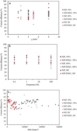
NiP coatings have slightly higher CE values than NiP/SiC coatings ((b)). By comparing CE values with respect to bath charge ((c)), it can be seen that the higher CE values of NiP coatings are related to their lower bath charge compared to composite ones.
3.2. Coatings composition
The composition of the coatings was determined by EDS analysis, and the results are shown in . In pulse plating of NiP coating, wt.%P decreased when increasing ip, which was also observed by Lin et al.Citation39. Higher current densities increase the formation of hydrogen bubbles, and, thus, less H+ is available on the surface of the cathode, which results in less reduction of phosphorous acid to elemental phosphorus.Citation26 In addition, by increasing the current density, due to higher H2 evolution CE values might decrease. Hence, depositions with less P content should take place at lower CE as well. However, this conclusion cannot be supported by the results in , where higher CE was obtained at higher ip, and higher CE with less wt.%P values was obtained in NiP coatings. Therefore, there should be some other parameters that affect the wt.%P as well as CE values of the depositions. For this purpose, wt.%P was measured with respect to the bath charge as plotted in (c). It can be seen that less bath charge, regardless of ip values, leads to less wt.%P and higher CE values; as a result, bath charge has more impact than ip on composition and CE values of NiP deposition.
Figure 2. wt.%P in NiP matrix versus (a) ip, (b,c) frequency and bath charge at iave: 4 A dm−2.
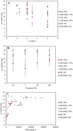
Wt.%P in DC plating for both NiP and composite coating at different current densities ((a and b)), changed between 14–16%, while for PC plating, it is more scattered and varied between 5–16% or 10–16% for NiP and composite baths, respectively. All the coatings that were produced had more than 10 wt.%P content except the NiP coatings that were produced by pulse plating.
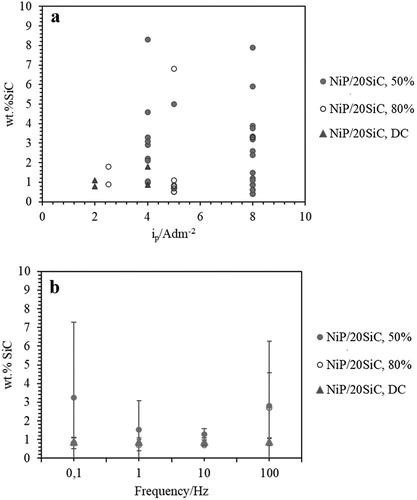
(a) shows that codeposition of SiC varied noticeably (∼0 to 8 wt.%) versus ip values. Guglielmi, in his two-step adsorption model, explained that higher current density increases the adsorption.Citation32,Citation40 In the meantime, by increasing current density, a higher amount of H2 bubbles can be produced, which can prevent the adsorption of SiC particles. According to (b), dc: 50% and f: 0.1 and 100 Hz result in higher, but scattered, codeposition values of wt.%SiC than the other parameters. Whereas, in DC plating, more stable codeposition values were obtained. It seems that the scattered codeposition value of SiC is not related to the current density ((a)) but non-uniform dispersion of SiC particles. It should also be considered that SiC particles were used from different batches and might have different surface chemistry or different shape, which affect their codeposition percentage.
Figure 3. Wt.%SiC in NiP coatings versus (a) ip, (b) frequency at iave: 4 A dm−2.
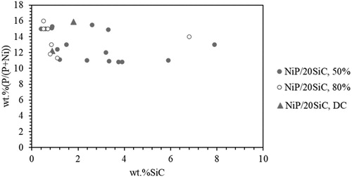
Previous reports have demonstrated that the increase in the SiC content of the coatings reduces the P content in the composites coatings.Citation33,Citation41,Citation42 However, in this study, there is not a relation between wt.%P and wt.%SiC particles in the matrix, as seen in . The composition of the NiP matrix was also little affected with the codeposition of alumina particles in the study by Balaraju et al.Citation43 study.
Figure 4. The effect of SiC codeposition on wt.%P in NiP composite coatings at iave: 4A dm−2.
3.3. Microstructure (XRD analysis) of the coatings
(a and b) shows the results of the XRD analysis of NiP coatings in as-plated condition at iave: 4 A dm−2, f: 0.1 and 100 Hz and dc: 50% and 80%, respectively. The XRD spectra show the characteristic peak of the amorphous NiP structure that has been reported in many other papers.Citation43,Citation44 The amorphous microstructure of NiP is due to the supersaturated P within the lattice, which results in the subsequent strain fields inhibition of grain growth.Citation45,Citation46 Frequency and duty cycle did not affect the microstructure of the coatings, as seen in (a and b).
Figure 5. XRD spectra of as-plated NiP and NiP/SiC coatings at iave: 4 A dm−2, f: 0.1 and 100 Hz (a,b) NiP, (c,d) NiP/SiC100, (a,c) dc: 50%, (b, d) dc: 80%.
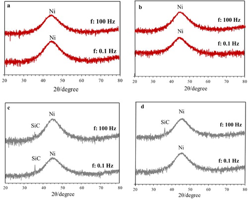
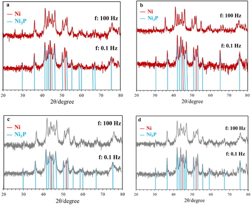
(c and d) are related to the microstructure of NiP/SiC coatings. The peak at 35.9° ((c and d)) corresponds to SiC, and it is clear that the addition of SiC particles did not change the microstructure of NiP coatings. SiC peaks are not visible in all plots of (c or d) due to their low percentage. In the case of composite coatings, the microstructure did not change due to duty cycle nor due to frequency, behaviour similar to what was observed in NiP deposits. The overall structure, however, has altered after the application of heat treatment (). Narrow intensive peaks in all cases proved the crystallisation process had occurred. The visible phases in the XRD spectra are crystalline Ni, FCC phase and Ni3P intermetallic phase.
Figure 6. XRD spectra of heat treated NiP and NiP/SiC coatings at iave: 4 A dm−2, f: 0.1 and 100 Hz (a,b) NiP, (c,d) NiP/SiC100, (a,c) dc: 50%, (b,d) dc: 80%.
3.4. Surface morphology of the coatings
presents the surface morphology of NiP and NiP/SiC coatings deposited at iave: 4 A dm−2. NiP coatings ((a–d)) have nodular morphology, and relatively smaller nodular character was obtained at f: 0.1 Hz and dc: 80% due to the higher nucleation. In all cases, nevertheless, the surface is smooth. As seen in (e,f,h), the introduction of SiC particles significantly changes the surface morphology, and rough surfaces were produced although the main pattern of the nodular development was preserved. Possible disarrangements and non-uniform distribution of these particles on the coating surface will be mirrored as subsequent potential surface perturbations.Citation47 However, (g) has similar morphology to NiP coatings due to the low percentage (less than 1 wt.%) of SiC codeposition. It should be mentioned that duty cycle and frequency do not affect the morphology of the coatings significantly, and it was the wt.%SiC particles in the matrix which had the most impact on coatings morphology.
Figure 7. SEM images of the coatings surface at iave: 4 A dm−2 (a–d) NiP, (e–h) NiP/SiC20, (i–l) NiP, heat treated, (m–p) NiP/SiC, heat treated, (a,e,i,m) dc: 50%, 0.1 Hz, (b,f,j,n) dc: 50%; 100 Hz, (c,g,k,o) dc: 80%, 0.1 Hz, (d,h,l,p) dc: 80%, 100 Hz.
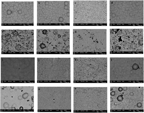
By heat treatment at 400°C for 1 h, the nodularity decreased, and the boundaries between the nodules became faded, and coatings become more compact than as-plated ones ((i–l)). It can be easily distinguished that heat treatment smooths the surface, in general. The effect of heat treatment is more profound in the case of SiC particle reinforced coatings, where heat treatment leads almost to an elimination of the formed surface imperfections. Multiple diffusion-driven phenomena are developed during heat treatment such as crystallisation, grain boundaries formation, grain boundary migration, grain growth, Ni3P and other Ni-P intermetallic phase precipitations.Citation11,Citation48 In addition, these coatings were heat treated in air; therefore an oxide layer was produced on the surface of these coatings, which also smooths their surfaces.
The average surface roughness and the RMS roughness of the coatings before and after heat treatment were extracted and plotted in . It can be noticed that both diagrams reveal the same tendency. The introduction of reinforcing particles, irrespective of the adopted process parameters, leads to a deterioration of the coating surface smoothness. This effect is probably related to reducing the continuity of the surface deposit by addition of particles. Since, in electroplating, deposition follows the surface pattern and topography, as the coating is growing, the initial perturbations due to particles become more intensive, and the roughness might become enhanced.
Figure 8. (a) Average surface roughness and (b) RMS roughness of the produced coatings.
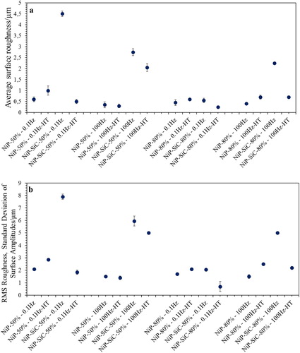
Composite coatings deposited at dc: 80% at 0.1 Hz have lower surface roughness values than the ones produced at dc: 50% which is associated with the particle concentration within the coating.
Heat treatment seems to have two different effects. In the case of the NiP coatings, the intensity of the surface roughness increased by heat treatment. Heat treatment induces crystallisation and grain boundaries which encourage features that can play a role in producing a rougher surface compared to amorphous coatings. Apart from this potential mechanism, the precipitation of Ni3P intermetallic phase has its role in increasing surface roughness. In contrast, in composite coatings () the application of heat treatment noticeably reduced the initial as-plated surface roughness. This tendency is most likely associated with the presence of an oxide layer on top of the coatings.
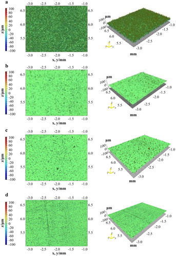
Indicatively, shows the 2D and 3D surface reconstruction after profilometry measurements, for the samples of the two extreme roughness conditions after plating (the highest and the lowest) and their alteration upon the application of heat treatment.
Figure 9. 2D and 3D surface reconstruction for NiP/SiC coatings at frequency of 0.1 Hz, (a,b) dc: 50%, (c,d) dc: 80%, (a,c) as plated, (b,d) HT.
3.5. Microhardnesses of the coatings
The microhardnesses of the coatings were measured on the cross-section of the coatings to avoid any influence of the softer substrate, and the results are shown in .
Figure 10. Microhardness values of NiP and composite coatings at iave: 4 A dm−2 versus (a) ip, (b) wt.%SiC, (c) frequency.
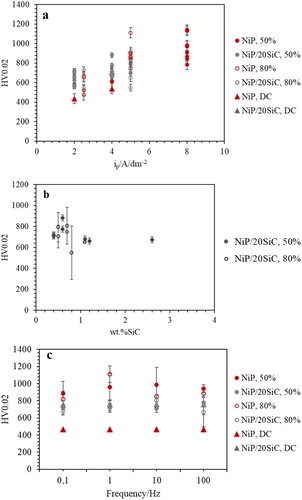
As can be seen in , the microhardness of NiP coatings increased by increasing ip ((a)), which can be related to lower wt.%P of these coatings at higher ip ((b)). The incorporation of SiC particles did not enhance the microhardness values of the coatings in pulse plating condition significantly ((c)). This can be attributed to the non-uniform distribution of SiC particles in the matrix, which was also confirmed by the high error bars in microhardness values. Balaraju et al.Citation43 also reported that Al2O3 particles did not cause substantial dispersion hardening in NiP/Al2O3 coatings, although there was around 8 wt.% Al2O3. Insignificant effect of hard particle content on the microhardness of NiP coatings was also observed by Sheu et al.Citation32
According to (b), the low value of SiC content has the most impact on enhancing microhardness values, similar to the observation in DC plated coatings ((b)), while, higher wt.%SiC might be achieved by agglomeration of SiC particles in the matrix which would not allow a role in dispersing hardening mechanism. According to these results, PC plating did not enhance the microhardness values of composite coatings compared to DC plated ones, while PC plating has the most impact on the microhardness of pure NiP coating. Hou et al.Citation33 observed higher microhardness values of NiP/SiC coatings in DC plated deposits than in the PC one. They attributed this result to less hydrogen in the structure of the PC plated coatings.
According to (c), the microhardness of PC plated coatings was not affected by the duty cycle or frequency.
displays the effect of wt.%SiC and wt.%P on microhardness values of NiP/SiC100 at different frequencies, dc: 50% and iave: 4 A dm−2 in as-plated and after heat treatment. It can be seen that the microhardness of as-plated coating at f: 100 Hz is higher than the rest which can be related to the lower wt.%P and a slightly higher wt.%SiC (two times more) in this coating.
Figure 11. The relation between microhardness before and after heat treatment with frequency, wt.%SiC and wt.%P in NiP/SiC coatings (deposited at dc: 50%, iave: 4 A dm−2).
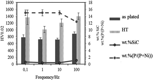
Heat treatment has a remarkable impact on microhardness values of NiP composite coatings and the hardening differs depending on the deposition conditions. The microhardness, wt.%P and wt.%SiC of the coatings in as-plated condition at f: 0.1, 1, 10 are similar while their microhardness values after heat treatment are not the same. Besides, the coating deposited at f: 100 Hz had the maximum microhardness before heat treatment, while after heat treatment it has a similar microhardness value to the coating formed at f: 0.1 Hz.
4. Conclusions
In this study, the effect of pulse plating parameters including current density, duty cycle and frequency on the properties of NiP and NiP/SiC coatings was studied, and it was shown that at the same average current density, pulse plating results in higher current efficiency, less wt.%P and, therefore, higher microhardness values of NiP coating compared to DC plating. However, in the case of NiP/SiC coatings, pulse plating could not enhance the codeposition of SiC particles significantly, and distribution of SiC particles in the matrix was not uniform; therefore, their microhardness values did not increase compared to that of NiP deposits. Bath charge influences the NiP composition, and hence it’s microhardness.
Acknowledgements
The experimental support regarding the bath composition of the present work by Professor Luca Magagnin (University of Politecnico di Milano) is highly acknowledged.
Disclosure statement
No potential conflict of interest was reported by the author(s).
Additional information
Funding
References
- A. Martínez-hernández, F. Manríquez-guerrero, J. Torres, R. Ortega, J. D. J. Pérez-bueno, Y. Meas, G. Trejo and A. Méndez-albores: ‘ Electrodeposition of Ni-P / SiC Composite Films with High Hardness’, Ch. 7 in ‘Electrodeposition of composite materials’, (ed. by A. M. A. Mohamed, Teresa D. Golden); 2016, IntechOpen.
- L. Wang, Y. Gao, Q. Xue, H. Liu and T. Xu: Surf. Coat. Technol., 2006, 200, 3719–3726. doi: 10.1016/j.surfcoat.2004.10.016
- L. Wu, Z. Yang and G. Qin: J. Alloys. Compd., 2017, 694, 1133–1139. doi: 10.1016/j.jallcom.2016.10.141
- H. Wang, S. Yao and S. Matsumura: Surf. Coat. Technol., 2002, 157, 166–170. doi: 10.1016/S0257-8972(02)00151-2
- D. Ahmadkhaniha, F. Eriksson, P. Leisner and C. Zanella: J. Alloys. Compd., 2018, 769, 1080–1087. doi: 10.1016/j.jallcom.2018.08.013
- K. G. Keong, W. Sha and S. Malinov: J. Alloys. Compd., 2002, 334, 192–199. doi: 10.1016/S0925-8388(01)01798-4
- I. Apachitei, F. D. Tichelaar, J. Duszczyk and L. Katgerman: Surf. Coat. Technol., 2002, 149, 263–278. doi: 10.1016/S0257-8972(01)01492-X
- M. Buchtík, P. Kosár, J. Wasserbauer, J. Tkacz and P. Doležal: Coatings, 2018, 8, 96–103. doi: 10.3390/coatings8030096
- S. Karthikeyan, L. Vijayaraghavan, S. Madhavan and A. Almeida: Metall. Mater. Trans. A Phys. Metall. Mater. Sci., 2016, 47, 2223–2231. doi: 10.1007/s11661-016-3413-y
- A. Zoikis-Karathanasis, E. A. Pavlatou and N. Spyrellis: Electrochim. Acta., 2009, 54, 2563–2570. doi: 10.1016/j.electacta.2008.07.027
- Q. Wang, M. Callisti, J. Greer, B. McKay, T. K. Milickovic, A. Zoikis-Karathanasis, I. Deligkiozi and T. Polcar: Wear, 2016, 356–357, 86–93. doi: 10.1016/j.wear.2016.03.011
- Q. Wang, M. Callisti, A. Miranda, B. McKay, I. Deligkiozi, T. K. Milickovic, A. Zoikis-Karathanasis, K. Hrissagis, L. Magagnin and T. Polcar: Surf. Coat. Technol., 2016, 302, 195–201. doi: 10.1016/j.surfcoat.2016.06.011
- S. Alirezaei, S. M. Monirvaghefi, M. Salehi, A. Saatchi and M. Kargosha: Surf. Eng., 2005, 21, 60–66. doi: 10.1179/174329305X23272
- D. Dong, X. H. Chen, W. T. Xiao, G. B. Yang and P. Y. Zhang: Appl. Surf. Sci., 2009, 255, 7051–7055. doi: 10.1016/j.apsusc.2009.03.039
- M. Sarret, C. Müller and A. Amell: Surf. Coat. Technol., 2006, 201, 389–395. doi: 10.1016/j.surfcoat.2005.11.127
- D. Vojtech: Mater. Manuf. Process., 2009, 24, 754–757. doi: 10.1080/10426910902809784
- R. Bernasconi, F. Allievi, H. Sadeghi and L. Magagnin: Trans. IMF., 2017, 95, 52–59. doi: 10.1080/00202967.2017.1263477
- A. Araghi and M. H. Paydar: Mater. Des., 2010, 31, 3095–3099. doi: 10.1016/j.matdes.2009.12.042
- Z. A. Hamid, S. A. El Badry and A. A. Aal: Surf. Coat. Technol., 2007, 201, 5948–5953. doi: 10.1016/j.surfcoat.2006.11.001
- Y. L. Shi, Z. Yang, H. Xu, M. K. Li and H. L. Li: J. Mater. Sci., 2004, 39, 5809–5815. doi: 10.1023/B:JMSC.0000040093.31790.d3
- C. S. Chang, K. H. Hou, M. Der Ger, C. K. Chung and J. F. Lin: Surf. Coat. Technol., 2016, 288, 135–143. doi: 10.1016/j.surfcoat.2016.01.020
- Y. de Hazan, D. Zimmermann, M. Z’graggen, S. Roos, C. Aneziris, H. Bollier, P. Fehr and T. Graule: Surf. Coat. Technol., 2010, 204, 3464–3470. doi: 10.1016/j.surfcoat.2010.04.007
- H. Mazaheri and S. R. Allahkaram: Appl. Surf. Sci., 2012, 258, 4574–4580. doi: 10.1016/j.apsusc.2012.01.031
- C. F. Malfatti, H. M. Veit, T. L. Menezes, J. Zoppas Ferreira, J. S. Rodriguês and J. P. Bonino: Surf. Coat. Technol., 2007, 201, 6318–6324. doi: 10.1016/j.surfcoat.2006.11.040
- J. Alexis, B. Etcheverry, J. D. Beguin and J. P. Bonino: Mater. Chem. Phys., 2010, 120, 244–250. doi: 10.1016/j.matchemphys.2009.12.013
- W. E. G. Hansal, G. Sandulache, R. Mann and P. Leisner: Electrochim. Acta., 2013, 114, 851–858. doi: 10.1016/j.electacta.2013.08.182
- N. Spyrellis, E. A. Pavlatou, S. Spanou and A. Zoikis-Karathansis: Trans. Nonferrous. Met. Soc. China, 2009, 19, 800–804. doi: 10.1016/S1003-6326(08)60353-2
- J. N. Balaraju and K. S. Rajam: J. Alloys Compd., 2008, 459, 311–319. doi: 10.1016/j.jallcom.2007.04.228
- S. Afroukhteh, C. Dehghanian and M. Emamy: Appl. Surf. Sci., 2012, 258, 2597–2601. doi: 10.1016/j.apsusc.2011.10.101
- P. Papavasilopoulou, E. Pavlatou and N. Spyrellis: Manuf. Eng., 2008, 1–3. Proceedings of the 7th International Conference Coatings in Manufacturing Engineering, 1–3 October 2008, Chalkidiki, Greece. Edited by: K.-D. Bouzakis, Fr.-W. Bach, B. Denkena, M. Geiger, 10 pp.
- B. Li, X. Li, Y. Huan, W. Xia and W. Zhang: J. Alloys Compd., 2018, 762, 133–142. doi: 10.1016/j.jallcom.2018.05.227
- H. H. Sheu, P. C. Huang, L. C. Tsai and K. H. Hou: Surf. Coat. Technol., 2013, 235, 529–535. doi: 10.1016/j.surfcoat.2013.08.020
- K. H. Hou, W. H. Hwu, S. T. Ke and M. Der Ger: Mater. Chem. Phys., 2006, 100, 54–59. doi: 10.1016/j.matchemphys.2005.12.016
- A. Zoikis-Karathanasis, E. A. Pavlatou and N. Spyrellis: J. Alloys Compd., 2010, 494, 396–403. doi: 10.1016/j.jallcom.2010.01.057
- K. Arunsunai Kumar, G. Paruthimal Kalaignan and V. S. Muralidharan: Ceram. Int., 2013, 39, 2827–2834. doi: 10.1016/j.ceramint.2012.09.054
- S. O. Pagotto, C. M. De Alvarenga Freire and M. Ballester: Surf. Coat. Technol., 1999, 122, 10–13. doi: 10.1016/S0257-8972(99)00401-6
- K. Dhanapal, V. Narayanan and A. Stephen: Mater. Chem. Phys., 2015, 166, 153–159. doi: 10.1016/j.matchemphys.2015.09.039
- D. Ahmadkhaniha and C. Zanella: Coatings, 2019, 9, 554–567. doi: 10.3390/coatings9090554
- C. S. Lin, C. Y. Lee, F. J. Chen, C. T. Chien, P. L. Lin and W. C. Chung: J. Electrochem. Soc., 153, 387–392. doi: 10.1149/1.2186798
- M. R. Vaezi, S. K. Sadrnezhaad and L. Nikzad: Colloids Surfaces A Physicochem. Eng. Asp., 2008, 315, 176–182. doi: 10.1016/j.colsurfa.2007.07.027
- S. Zhang, K. Han and L. Cheng: Surf. Coat. Technol., 2008, 202, 2807–2812. doi: 10.1016/j.surfcoat.2007.10.015
- J. N. Balaraju, V. E. Selvi, V. K. W. Grips and K. S. Rajam: Electrochim. Acta., 2006, 52, 1064–1074. doi: 10.1016/j.electacta.2006.07.001
- J. N. Balaraju, Kalavati and K. S. Rajam: Surf. Coat. Technol., 2006, 200, 3933–3941. doi: 10.1016/j.surfcoat.2005.03.007
- Y. Wu, B. Shen, L. Liu and W. Hu: Wear, 2006, 261, 201–207. doi: 10.1016/j.wear.2005.09.008
- Y. Wu, L. Liu, B. Shen and W. Hu: J. Mater. Sci., 2005, 40, 5057–5059. doi: 10.1007/s10853-005-1807-0
- P. Sahoo and S. K. Das: Mater. Des., 2011, 32, 1760–1775. doi: 10.1016/j.matdes.2010.11.013
- J. Sudagar, J. Lian and W. Sha: J. Alloys Compd., 2013, 571, 183–204. doi: 10.1016/j.jallcom.2013.03.107
- F. Bahrami, R. Amini and A. H. Taghvaei: J. Alloys Compd., 2017, 714, 530–536. doi: 10.1016/j.jallcom.2017.04.069