
 ?Mathematical formulae have been encoded as MathML and are displayed in this HTML version using MathJax in order to improve their display. Uncheck the box to turn MathJax off. This feature requires Javascript. Click on a formula to zoom.
ABSTRACT
To execute soft switching methods in resonant power converters, transformers with larger leakage inductance are getting more attention. Many papers have constructed various concepts in this regard. However, a discussion about, how the transformer efficiency is affected is lacking in the literature. This paper analyses the effects of the increased leakage inductance on the performance of the transformer. A transformer for increased leakage inductance is modelled and constructed to investigate the losses. The model discusses the effects of increased leakage inductance either by increasing the inter-winding spacing or by integrating the magnetic shunt within the transformer. The investigations show that increasing the leakage inductance by inserting a magnetic shunt can have severe degrading effects on the performance of the transformer, if not designed adequately. Additional losses are also calculated and the effects are verified by the experiments.
Introduction
Better efficiency and improved power density are the two major concerns of the present power electronics industry (Demirel & Erkmen, Citation2014; Yang et al., Citation2016; Zhu et al., Citation2019). The higher power density can be achieved by reducing the dimensions of the semiconductors and the magnetics. The purpose of low profile components can be achieved by increasing the operating frequency (Ji et al., Citation2013). On the other hand, this increased switching frequency results in increased switching and magnetic loss because of the increased parasitic capacitance, leakage inductance, core loss, and the winding loss. The switching loss has a direct relationship with the frequency of operation in a hard switched power converters. Therefore, soft switched resonant power converters are getting more attention (Ayyanar & Mohan, Citation2001; Pajnic et al., Citation2017; Reusch & Strydom, Citation2015; Wang & Wang, Citation2019; Witulski et al., Citation1991; Wu et al., Citation2015; Yadav & Narasamma, Citation2014) in order to reduce these losses.
A contrary to the hard switched converter, the power switch is turned ON when the voltage across the drain-source node is zero in resonant power converters. By employing the soft switched techniques, the operating frequency can be increased while keeping the converter’s efficiency the same or improved (Witulski et al., Citation1991; Yadav & Narasamma, Citation2014). In this regard, the resonance inductance of the main transformer plays a vital role to obtain soft switching. When the power switch turns OFF, resonance inductance creates oscillations together with the parasitic capacitance. The zero voltage switching (ZVS) of all the power devices, in most of the cases, cannot be obtained for the entire operating conditions by using only the intrinsic leakage inductance (Shirsavar et al., Citation2013; Yu et al., Citation2014), as it is often not sufficient. The converter may enter into hard switching at light load. To this end, the total resonance inductance of the transformer is increased by adding an extra resonance inductor in series with the main transformer. This makes the converter less favourable in terms of power density.
An extensive work (Bahmani & Thiringer, Citation2015; Choi et al., Citation2012; Ferrell et al., Citation2004; Hackner & Pforr, Citation2011; Margueron et al., Citation2010; Ortiz et al., Citation2010; Ouyang et al., Citation2009) is carried out to increase the intrinsic resonance inductance of the main transformer. Some (Hackner & Pforr, Citation2011; Ouyang et al., Citation2009) have studied the increase of total leakage inductance by employing new winding strategies. In (Bahmani & Thiringer, Citation2015; Choi et al., Citation2012; Ferrell et al., Citation2004; Margueron et al., Citation2010; Ortiz et al., Citation2010), the total resonance inductance is increased by expanding the inter-winding distance between the windings. Because of the dimension constraint for inter-winding spacing, the methods (Ouyang & Andersen, Citation2014; Zhang et al., Citation2014) propose to integrate a magnetic material with the transformer in order to increase the total resonance inductance. Although considerable work has been carried out to make the leakage inductance larger, studying the consequences of this increased leakage inductance has received less attention. The addition of magnetic material in the leakage path results in more flux to follow this path. This increased leakage flux may also increase the losses of the transformer, which has not been thoroughly discussed in the literature. The main focus has been on increasing the leakage inductance and neither has studied the additional losses in the transformer that would appear by the insertion of magnetic material. For proper thermal management and performance evaluation, it is important to estimate the losses at the design stage.
This article investigates the effects of this increased leakage inductance. The loss contribution of the added magnetic material in the transformer is analysed. An improved transformer model to get the larger leakage inductance both by expanding the transformer windings and by adding the magnetic material between them has been presented in our previous work (Bakar & Bertilsson, Citation2016), which investigates the model both analytically and experimentally. An example application (Bakar et al., Citation2016) of the model has also been demonstrated by applying it in the phase shifted full bridge converter. The model is rearranged to estimate the contribution of the increased leakage flux to the total losses of the transformer. The model is investigated both analytically and experimentally. Experimental investigations are produced by building a transformer for larger resonance inductance. These estimations show a significant contribution to the total losses of the power transformer caused by the increased leakage inductance.
Modelling of the transformer for the estimation of losses in the leakage path
As stated before, to improve the power density of the resonant power converters, continuous research is going on to embed the external resonance inductance inside the main transformer. To study the scope of increasing the total leakage inductance either by integrating the external inductor into the transformer or by moving the windings apart, the total losses need to be investigated, both in the transformer core and in the magnetic material inside the leakage path. The method (Cougo & Kolar, Citation2012) has studied the loss only in the core for the various orientations of the magnetic shunt in amorphous and nanocrystalline tape wound core transformers. In these cores, the loss is highly asymmetric depending on the flux orientation. Compared to the losses related to the flux perpendicular to the lamination, the authors concluded that, in the case of ferrite cores, there will be no extra loss because of the integration of the magnetic material. Authors in (Zhang et al., Citation2014) identify in a FEA simulation that the integrated magnetic shunt has the highest magnetic field intensity in the structure, and no further investigations are available for this section. Therefore, total losses need to be estimated before implementing the transformer in the final design.
For the mathematical investigation of the loss both by the increased inter-winding spacing and by the introduction of the magnetic material inside the transformer, a model of the transformer is created in order to investigate each section. The layout plan and the model are shown in respectively.
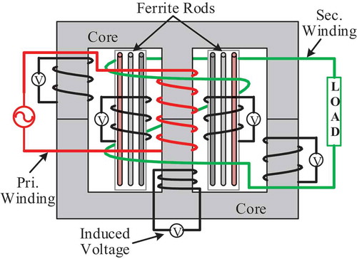
Figure 1. Structure of the transformer
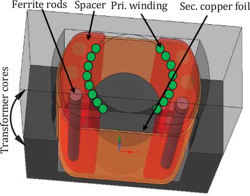
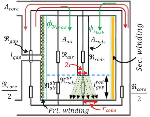
Figure 2. Reluctance based model for the estimation of losses
As shown in , the inter-winding distance has increased due to the addition of a spacer between the windings. In the spacer, channels for the ferrite rods are also shown, to set the desired value of the leakage inductance, ferrite rods are added or removed.
As presented in previous article (Bakar & Bertilsson, Citation2016) this analytical model predicts the total resonance inductance of the transformer with good accuracy. Here the model is restructured to estimate the losses in the transformer due to this increased leakage inductance. , shows the reluctance based model of the transformer to calculate the possible losses which might be caused by the increased leakage inductance. The reluctance of the core, and the reluctance of the air-gap are shown as ℜcore and ℜgap respectively. To make the model simple, the air-gap is modelled only in the centre leg of the transformer. When there is zero air-gap, the reluctance, ℜgap is equal to zero. In the model, it is considered that the spacer’s reluctance, ℜ and the rod’s reluctance,
are in a parallel configuration. The reluctance and the length of air-gap between the core and the rod are shown as ℜ
and
respectively. Similarly, ℜ
is the reluctance of the air-gap between the core and the spacer.
In transformers, the flux from the induced secondary current nearly cancels the primary flux. In such a case, it is not the current that determines the magnetising flux in the core, instead, it is the volt-second relationship as shown in EquationEquation (1)(1)
(1) (Erickson & Maksimović, Citation2001).
where B is the flux density, Vpri is the voltage on the primary winding of the transformer, Aeff represents the core’s effective cross-sectional area and Np is the number of primary turns. In , it can be observed that the situation is different in the leakage path. The two fluxes are cancelling each other in the core, and are added to the leakage path. In this case, the leakage flux can then be calculated as:
where and
are the reluctance of the leakage path in the primary side and the secondary side respectively, Ip is the transformer primary current, k is the coupling factor and is given by
where LMag, Lpri, and Lsec are respectively the magnetising inductance, primary inductance, and the secondary inductance. As long as the coupling factor remains high and the leakage path is fairly symmetrical, the leakage flux will be proportional to twice the input current. In the case of a loaded transformer, this contribution is much greater than the volt-second relationship which is independent of the loading conditions. In order to solve the above equations, the variables are estimated as follows.
The reluctance of each section is first calculated. After this, the effective permeability of each section is estimated. By using the new effective permeability the required inductances are calculated. The reluctance of each section is estimated by using the general EquationEquation (4)(4)
(4) and substituting the respective parameters for each section.
where µ0 is the permeability of the air, µr is core’s relative permeability, leff is the effective length of the magnetic path in the used core.
where µrrod, and lrod are respectively the relative permeability and the length of the rod. Nrods is the number of integrated rods in the spacer.
As seen in , the flux spreads conically in the air-gap , so the reluctance is considered as the truncated cone. Here the magnetic flux is assumed to spread conically at an angle of 45° with the reluctance
. The reluctance in this region is calculated as a truncated air cone with a smaller radius equals to
and a larger radius
. The truncated cone approach is required for the model to fit with the actual leakage inductance. A cylinder of air with the same diameter as the rod will underestimate the leakage inductance and an area equal to the spacer will overestimate it. Next to this air-gap, the reluctance is calculated from the air volume subtracting this truncated cone from the spacer volume of height
. The reluctances in that regions can be calculated as
After the calculation of the reluctance in each section, the reluctance of the leakage path, is calculated as given in EquationEquation (10)
(10)
(10) .
The reluctance in the leakage path seen from the primary side is calculated as
Since in the model, the air-gap in the core is considered only in the centre leg and the secondary winding is assumed on the other side of the ferrite rods, so the reluctance in the leakage path seen from the secondary winding can be expressed as
The primary winding’s effective permeability is estimated by using the reluctances seen by the primary winding as given in EquationEquation 13(13)
(13) .
Similarly, the effective permeability of the secondary winding is given in EquationEquation 14(14)
(14) .
By the addition of magnetic material in the leakage path, the leakage flux has to flow through different paths of permeability (Yan et al., Citation2003). The effective permeability of both the primary side and the secondary side in the leakage path is calculated again as given in EquationEquations (15)(15)
(15) and (Equation16
(16)
(16) ).
By using effective permeability, the inductance of the primary winding, inductance of the secondary winding, leakage inductance of the primary side and leakage inductance of the secondary side are calculated by EquationEquation 17(17)
(17) (Erickson & Maksimović, Citation2001; McLyman & Mclyman, Citation2011; Snelling, Citation1972).
The magnetising inductance is:
where Lpri and LleakP are respectively the self and the leakage inductance of the primary winding.
Analytical estimation of the losses in the leakage path
In traditional transformer design or by increasing the inter-winding spacing, the leakage flux has no severe effect as there is no lossy material in the leakage path. However, in the case of transformer design with magnetic material in the leakage path, the effect must be accounted for as it degrades the transformer efficiency and generates excessive heat in a place where it might be difficult to dissipate. In the literature, the flux in the leakage path is often assumed to be proportional to the core flux. To verify that this is not the case, first the losses are estimated mathematically by writing the modelled equations in a matlab script and then the losses are measured and compared by performing an experimental work on an example transformer.
The script is used to estimate the magnetic flux, flux density, losses and transformer efficiency for different configuration/length of the rods. The calculations are based on the application where the transformer input voltage is 100 V, the primary current is 5A. The other parameters required for the calculations are given in .
Table 1. Transformer specifications
Since magnetic material having a higher permeability than air is present in the spacer, the contribution of ferrite rods towards the flow of leakage flux will be higher. This increased flux will ultimately increase the total loss of the transformer. This is investigated in the following discussion.
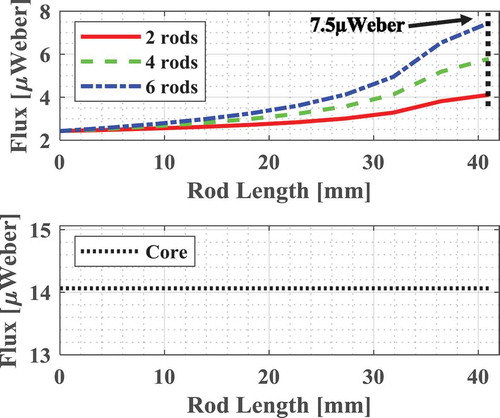
Taking the loss in the leakage path into consideration, the magnetic flux in the core and the rods are calculated with a different number of rods and for varying length as shown in . The flux in the rods is calculated according to EquationEquation (2)(2)
(2) . As seen, the flux increases when the length of air-gap in the leakage path is reduced. The addition of more rods also increases the amount of flux because of the decreased reluctance. The flux in the core remains unchanged because it depends upon the applied volt-second relationship (1) and is independent of the loading conditions (Erickson & Maksimović, Citation2001).
Figure 3. Magnetic leakage flux flowing both in the core and in ferrite rods for the change in length and quantity of rods
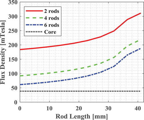
By using the flux calculated for each configuration, the flux density is also plotted. shows the plot of flux density in core and rods. The flux density becomes smaller with the increased number of rods, as more rods increase the available effective area of the ferrite material in the leakage path. Since flux remains unchanged in the core, the flux density also remains constant against the length and quantity of ferrite rods.
Figure 4. Change in magnetic flux density both in the core and in the ferrite rods for varying length and number of rods
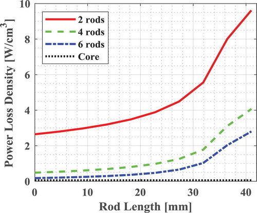
From the calculated flux densities, the loss densities are calculated by using the manufacturer’s Core Loss vs. Flux density graph as a function of frequency PV = f(B) for the chosen core material. The calculated loss densities are shown in . As seen, it is similar to the flux density but more compressed due to the exponential behaviour of PV = f(B). The volume of the core is many times higher than the volume of the rod, therefore, the loss density of the core is very small and appears just above the zero axis.
Figure 5. Power loss density in the core and in the ferrite rods
As the rods are much smaller in volume, the absolute value of the loss is calculated and shown in . From this analysis, it can be concluded that for short rods the absolute power loss is not significant, but careful design and thermal management are required. The increased length of rods results in a shorter length of air-gap and consequently the more losses. With the length of rods above approximately 35 mm in this
Figure 6. Absolute power loss in the core and in the ferrite rods
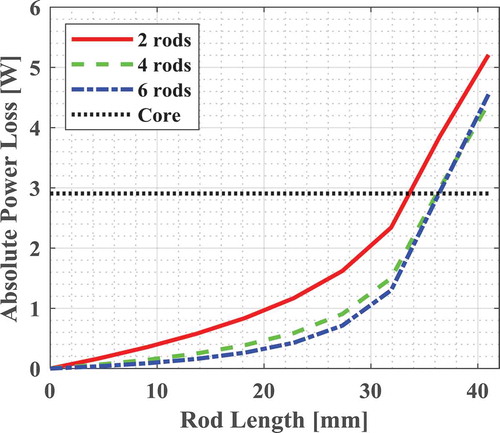
case, the loss in the leakage path dominates over the core in absolute number as well.
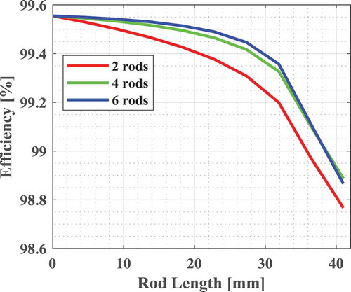
shows the efficiency curves of the transformer for different configurations of the rod length and quantity. The efficiency curves are plotted by adding together the losses in the core and in the ferrite rods. As seen the efficiency drops in each case as the length of the magnetic material increases. There is more efficiency drop in the case of 2 rods, this is due to the fact that the loss in the ferrite material increases as the flux density increases. Since the loss in the core remains constant therefore the higher is the permeability of the material in the leakage path, the more is the efficiency drop.
Figure 7. The effect on the performance of the transformer for varying length and quantity of ferrite rods in the leakage path
Experimental validation of the proposed model
In order to validate the proposed model, two experimental setups have been made by designing the transformer with the same parameters as given in . In the first setup, the induced flux is calculated and compared with the analytical model, in the other setup the temperature profile of the transformer is monitored in the leakage path together with rods. In order to make the comparison accurate, a method presented in (Ortiz et al., Citation2014) for the measurement of continues flow of flux has been adopted in the first setup. This further eliminates the need to instal a hall sensor which requires air-gap and adds complexities in the measurements. The methodology adopted for the design of the transformer with increased leakage inductance is explained in (Bakar & Bertilsson, Citation2016). Here the transformer will be used to examine the losses in the leakage path. As shown earlier in , a spacer along with the six channels is fabricated according to the dimensions of the bobbin and ferrite rods. This spacer is then placed between the windings. The ferrite rods used in this experiment has the same material properties as the core. The transformer winding layout arranged for the measurement is shown in . Two turns of enamelled copper wire are wound on both legs of the spacer.
Figure 8. Transformer winding layout plan for the experimental measurements
These turns are spread around the whole length of the spacer in order to ensure maximum flux linkage. Similarly, two turns of enamelled copper wire are wound directly on the central and side legs of the core. Then channels are filled in steps with a number of ferrite rods while keeping the symmetry on both legs. For example, one channel on each side filled with ferrite rod makes the total number of rods equals two.
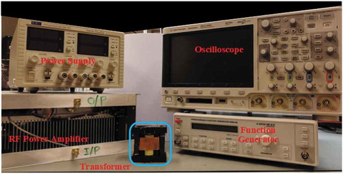
In every step, the induced voltage is monitored on the oscilloscope. The primary winding of the transformer is powered by a sinusoidal waveform by using EMPOWER (BBM0A3FKO) RF power amplifier. shows the experimental setup, where a function generator provides the input to the RF power amplifier, after the amplification to 100Vac at 400 kHz, it is then applied to the input terminals of the transformer. The induced voltage is captured on the oscilloscope for each increase in the number of ferrite rods in the channels.
Figure 9. Experimental setup, showing the equipment and the transformer under test
Afterwards, the magnetic flux is calculated by using the equation . The measurements also show the same trend as the analytical calculations shown in , where magnetic flux in the leakage path increases as the quantity of the ferrite material increases in that path.
As an example case of 2, 4 and 6 full-length rods, the flux measured both in core and rods is shown in . In order to make the comparison with the model, a dashed line is drawn in at the point where these measurements have been recorded.
Figure 10. Measured flux in the core and in ferrite rods with 2, 4 and 6 full-length rods
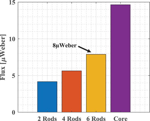
As seen, the amount of flux is comparable with the model in each case. For example, in the case of six full-length rods, the amount of flux in the rods is 7.5µweber in the analytical model and it is approximately 8µweber in the experimental measurement. Similarly, the amount of flux in the core is almost the same in both figures. Once the amount of flux is known, the contribution of loss for each case can be evaluated as explained in the analytical section. The absolute power loss from the measured flux comes out approximately as 45 watts and 3watts in the rods and in the core respectively. It is approximately the same as shown in , where it is 40 watts and 2.9 watts respectively. It can be concluded that the loss in the leakage path becomes more dominant than the loss in the core as the quantity of the ferrite material increases. Therefore, the increase in the leakage inductance by using the magnetic shunt inside causes more losses in the transformer.
For the monitoring of the temperature profile in the leakage path, one full-length ferrite rod is inserted on both sides of the spacer. A single hole is drilled in the spacer to monitor the temperature profile of the integrated ferrite rods as shown in . In order to maximise the flux in the leakage path, the secondary winding having one turn of copper foil is shorted by soldering its terminals together to provide a low impedance short. In this case, the induced secondary flux effectively magnetises the core with a flux cancelling the primary flux and the net flux will be very small. The temperature profile is monitored both by using an infra-red thermal camera and thermocouple elements. With low heating where the cooling effect from its surroundings is small, the temperature rise will then be nearly proportional to the loss density in the actual part. The primary winding of the transformer is powered by a sinusoidal waveform by using the same RF power amplifier and the temperature is constantly monitored. Since the probes of thermocouple are not tightly attached to the ferrites rods, a difference in both measurement methods is expected.
Figure 11. A hole is drilled in the spacer to be able to see the rods in the leakage path (left) and measure of its temperature (right)
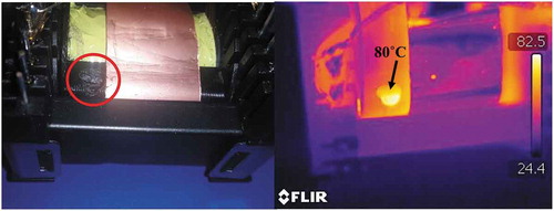
The thermocouple elements record a temperature of 55.3°C/30.9°C for the rod/core respectively, and in (right), the temperature of the rod is clearly much higher than in the core and it can be concluded that the loss density and consequently the flux density in the rods placed in the leakage path is much higher than in the main core.
As explained earlier, this is because of the fact, that flux intensity is greater in the leakage path where the primary and the secondary leakage flux adds up opposite to the core where it cancels each other.
Two more measurements are performed, one by leaving the secondary winding open ( left) and the other by loading the secondary winding with 10 Ω power resistor ( right). In the case where the secondary winding is left open, there is no flux for cancellation from the secondary side and the transformer acts as a large inductor. The thermocouple elements record a temperature of 29.0°C/30.3°C for the rod/core in this situation. From this, it can be concluded that the flux density is higher in the core as compared to the rod. This is as expected with no flux cancellation and a larger air-gap in the leakage path.
Figure 12. Thermal images of transformer unloaded (left) and with 10 Ω load (right)
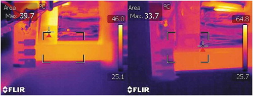
With 10 Ω load, the secondary current starts to flow again, cancels the primary flux by reducing the magnetising flux. The flux in the rod is expected to be higher as the two fluxes add up and the thermocouples read 35.2°C/30.1°C for the rod/core respectively. It is clear that the rods are hotter than the core, it means the flux density is higher in the rods compared to the core. It again validates that the loss density in the leakage path is higher than in the core.
Conclusion
The loss analysis of the transformer with magnetic material in the leakage path is discussed. The analysis shows that the increase in leakage inductance comes at the cost of more losses in the transformer. This will, of course, be the same case, when using a discrete inductor in series with the transformer to maintain the soft switching conditions. The flux in the leakage path is greater than the flux in the core under normal loaded operation and is not proportional to the flux in the core. This is explained as the flux from the primary and the secondary windings add up in the leakage path instead of cancelling each other as in the core. Instead of increasing the length of the rod, the increased number of rods i.e. the larger area could help to reduce loss in the leakage path. The additional leakage inductance achieved by integrating the external resonance inductor into the transformer behaves like an inductor having higher flux densities. This might give some room for improvement by using a smart combination of magnetic materials, and by using a material in the leakage path optimised for power inductors rather than a transformer. On the other hand, the losses dissipate heat inside the transformer, which is difficult to manage and limits the scope of this approach. The increase in leakage inductance achieved by only moving the windings apart, do not increase the core losses as there is then no lossy material in the leakage path. Negative consequences are the reduced useful window area and the increased wire length, which results in increased copper losses. As a part of future work, the losses will be investigated in an example application and/or by using a material having the characteristics of reduced losses at high temperature.
Disclosure statement
No potential conflict of interest was reported by the authors.
References
- Ayyanar, R., & Mohan, N. (2001). Novel soft-switching DC-DC converter with full ZVS-range and reduced filter requirement - Part II: Constant-input, variable-output applications. IEEE Transactions on Power Electronics, 16(2), 193–200. https://doi.org/10.1109/63.911143
- Bahmani, M. A., & Thiringer, T. (2015). Accurate evaluation of leakage inductance in high-frequency transformers using an improved frequency-dependent expression. IEEE Transactions on Power Electronics, 30(10), 5738–5745. https://doi.org/10.1109/TPEL.2014.2371057
- Bakar, M. A., Alam, F., & Bertilsson, K. (2016). A phase shifted full bridge converter with novel control over the leakage inductance. In 2016 18th European conference on power electronics and applications (EPE’16 ECCE Europe), IEEE (pp. 1–10). https://doi.org/10.1109/EPE.2016.7695545
- Bakar, M. A., & Bertilsson, K. (2016). An improved modelling and construction of power transformer for controlled leakage inductance. In 2016 IEEE 16th international conference on environment and electrical engineering (EEEIC), IEEE (pp. 1–5). https://doi.org/10.1109/EEEIC.2016.7555605
- Choi, J.-M., Byen, B.-J., Lee, Y.-J., Han, D.-H., Kho, H.-S., & Choe, G.-H. (2012). Design of leakage inductance in resonant DC-DC converter for electric vehicle charger. IEEE Transactions on Magnetics, 48(11), 4417–4420. https://doi.org/10.1109/TMAG.2012.2196027
- Cougo, B., & Kolar, J. W. (2012). Integration of leakage inductance in tape wound core transformers for dual active bridge converters. In 2012 7th international conference on integrated power electronics systems, CIPS 2012, 9 (Cips), IEEE (pp. 1–6). file:///Volumes/Jordi_backup/desktop/publications/papers/2012_Cougo_IntegrationLeakIndTransformer_CIPS.pdf
- Demirel, I., & Erkmen, B. (2014). A very low-profile dual output LLC resonant converter for LCD/LED TV applications. IEEE Transactions on Power Electronics, 29(7), 3514–3524. https://doi.org/10.1109/TPEL.2013.2278715
- Erickson, R. W., & Maksimović, D. (2001). Fundamentals of power electronics. In focus, Copyright 2001 by Kluwer Academic Publishers, Sixth Printing 2004. 500-504, 565-569. . https://doi.org/10.1007/b100747
- Ferrell, J., Lai, J.-S., Nergaard, T., Huang, X., Zhu, L., & Davis, R. (2004). The role of parasitic inductance in high-power planar transformer design and converter integration. In Nineteenth annual IEEE applied power electronics conference and exposition, 2004. APEC ’04., 1 (C), IEEE (pp. 510–515). https://doi.org/10.1109/APEC.2004.1295855
- Hackner, T., & Pforr, J. (2011). Optimization of the winding arrangement to increase the leakage inductance of a synchronous machine with multi-functional converter drive. In 2011 IEEE energy conversion congress and exposition, IEEE (pp. 1541–1548). https://doi.org/10.1109/ECCE.2011.6063965
- Ji, S., Reusch, D., & Lee, F. C. (2013). High-frequency high power density 3-D integrated gallium-nitride-based point of load module design. IEEE Transactions on Power Electronics, 28(9), 4216–4226. https://doi.org/10.1109/TPEL.2012.2235859
- Margueron, X., Besri, A., Jeannin, P.-O., Keradec, J.-P., & Parent, G. (2010). Complete analytical calculation of static leakage parameters: A step toward HF transformer optimization. IEEE Transactions on Industry Applications, 46(3), 1055–1063. https://doi.org/10.1109/TIA.2010.2045327
- McLyman, W. T., & Mclyman, C. W. M. T. (2011). Power transformer design. In Transformer and inductor design handbook (4th ed., pp. 30–60, 100–500). CRC Press. https://doi.org/10.1201/b10865-8
- Ortiz, G., Biela, J., & Kolar, J. W. (2010). Optimized design of medium frequency transformers with high isolation requirements. In IECON 2010-36th annual conference on IEEE industrial electronics society , IEEE(pp. 631–638). https://doi.org/10.1109/IECON.2010.5675240
- Ortiz, G., Fassler, L., Kolar, J. W., & Apeldoorn, O. (2014). Flux balancing of isolation transformers and application of “The magnetic ear” for closed-loop volt-second compensation. IEEE Transactions on Power Electronics, 29(8), 4078–4090. https://doi.org/10.1109/TPEL.2013.2294551
- Ouyang, Z., & Andersen, M. A. E. (2014). Overview of planar magnetic technology - Fundamental properties. IEEE Transactions on Power Electronics, 29(9), 4888–4900. https://doi.org/10.1109/TPEL.2013.2283263
- Ouyang, Z., Thomsen, O. C., & Andersen, M. A. E. (2009). The analysis and comparison of leakage inductance in different winding arrangements for planar transformer. In Proceedings of the international conference on power electronics and drive systems, IEEE (pp. 1143–1148). https://doi.org/10.1109/PEDS.2009.5385844
- Pajnic, M., Pejovic, P., Despotovic, Z., Lazic, M., & Skender, M. (2017). Design consideration for high frequency LLC resonant converter with matrix transformer. In 2017 international symposium on power electronics (Ee), IEEE. December, 1–6. https://doi.org/10.1109/PEE.2017.8171669
- Reusch, D., & Strydom, J. (2015). Evaluation of gallium nitride transistors in high frequency resonant and soft-switching DC-DC converters. IEEE Transactions on Power Electronics, 30(9), 5151–5158. https://doi.org/10.1109/TPEL.2014.2364799
- Shirsavar, S. A., Hallworth, M., & Ben Potter, A. (2013). Analytical calculation of resonant inductance for zero voltage switching in phase-shifted full-bridge converters. IET Power Electronics, 6(3), 523–534. https://doi.org/10.1049/iet-pel.2012.0461
- Snelling, E. C. (1972). Ferrites for linear applications- 2. IEEE Spectrum, 9(2), 26–32. https://doi.org/10.1109/MSPEC.1972.5218471
- Wang, Q., & Wang, Y. (2019). Resonant DC link soft-switching inverter with low-loss auxiliary circuit. International Journal of Electronics, 106(10), 1602–1615. https://doi.org/10.1080/00207217.2019.1600743
- Witulski, A. F., Hernandez, A. F., & Erickson, R. W. (1991). Small signal equivalent circuit modeling of resonant converters. IEEE Transactions on Power Electronics, 6(1), 11–27. https://doi.org/10.1109/63.64999
- Wu, H., Xu, P., Xing, Y., Chen, L., & Xiao, X. (2015). Two-transformer-based full-bridge soft-switching DC–DC converter with improved characteristics. IET Power Electronics, 8(12), 2537–2545. https://doi.org/10.1049/iet-pel.2014.0837
- Yadav, G. N. B., & Narasamma, N. L. (2014). An active soft switched phase-shifted full-bridge DC-DC converter: Analysis, modeling, design, and implementation. IEEE Transactions on Power Electronics, 29(9), 4538–4550. https://doi.org/10.1109/TPEL.2013.2284780
- Yan, L., Dayu, Q., & Lehman, B. (2003). Integrated magnetic full wave converter with flexible output inductor. IEEE Transactions on Power Electronics, 18(2), 670–678. https://doi.org/10.1109/TPEL.2003.809357
- Yang, J. W., Keum, M. H., Choi, Y., & Han, S. K. (2016). A high power density 50kW bi-directional converter for hybrid electronic vehicle HDC. In IET Conference Publications, 2016 (CP684), IET (p. 6). https://doi.org/10.1049/cp.2016.0199
- Yu, M., Sha, D., Guo, Z., & Liao, X. (2014). Hybrid PS full bridge and LLC half bridge DC-DC converter for low-voltage and high-current output applications. In Conference proceedings - IEEE applied power electronics conference and exposition - APEC, 7 (October 2013), IEEE. (pp. 1088–1094). https://doi.org/10.1109/APEC.2014.6803442
- Zhang, J., Ouyang, Z., Duffy, M. C., Andersen, M. A. E., & Hurley, W. G. (2014). Leakage inductance calculation for planar transformers with a magnetic shunt. IEEE Transactions on Industry Applications, 50(6), 4107–4112. https://doi.org/10.1109/TIA.2014.2322140
- Zhu, J., Qian, Q., Zhan, C., Lu, S., & Sun, W. (2019). ZVS Buck-Boost LLC cascade converter with all soft switched switches. International Journal of Electronics, 106(6), 895–911. https://doi.org/10.1080/00207217.2019.1575987