
 ?Mathematical formulae have been encoded as MathML and are displayed in this HTML version using MathJax in order to improve their display. Uncheck the box to turn MathJax off. This feature requires Javascript. Click on a formula to zoom.
ABSTRACT
In the framework of the Cost Action CERTBOND (Reliable roadmap for certification of bonded primary structures), a wide group of researchers from 27 European Countries have had the opportunity to work on the topic of certification of bonded joints for primary structural applications from different engineering sectors such as the aerospace, automotive, civil engineering, wind energy and marine sectors. Since virtual testing and optimization are basic tools in the certification process, one of the key objectives of CERTBOND is to critically review some of the available models and failure theories for adhesive joints. The present paper summarizes the outcome of this task. Nine different models/theories are described in detail. Specifically, reviewed are the Classical Analytical Methods, the Process Zone Methods, Linear Elastic Fracture Mechanics (LEFM), the Virtual Crack Closure Technique (VCCT), the Stress Singularity Approach, Finite Fracture Mechanics (FFM), the Cohesive Zone Method (CZM), the Progressive Damage Modeling method and the Probabilistic methods. Also, at the end of the paper, the modeling of temperature effects on adhesive joints have been addressed. For each model/theory, information on the methodology, the required input, the main results, the advantages and disadvantages and the applications are given.
1. Introduction
Adhesive joining technology finds an increasing use in assembly and repair applications in the aerospace, automotive, marine and civil structures sectors due to its many advantages over mechanical joining techniques .[Citation1–3] The adhesive joining applications are restricted to secondary structures due to stringent certification guidelines. The main reasons for the lack of certification of primary adhesively bonded structures are the uncertainty of the quality of the bondline, combined with the inability of the existing non-destructive testing methods to fully detect defects and characterize surface quality, and the inability to control by design the crack growth rate and length in the bondline. For the aerospace sector, the proposed means of compliance that describe the methodologies/measures that need to be undertaken are the following ones[Citation4]: (i) The maximum disbonds of each bonded joint consistent with the capability to withstand the loads […] must be determined by analysis, tests, or both. Disbonds of each bonded joint greater than this must be prevented by design features. (ii) Proof testing must be conducted on each production article that will apply the critical limit design load to each critical bonded joint; or (iii) Repeatable and reliable non-destructive inspection techniques must be established that ensure the strength of each joint. Evaluating these means of compliance in the context of large-scale structures, we conclude that the only feasible measure is the limitation of the maximum disbond size, whereas proof testing is cost-prohibitive and non-destructive techniques have not yet the capability to measure or correlate bonding strength to date. Given that the mean of compliance (i) may be reached by analysis and/or tests, the role of models towards certification is crucial.
In 2019, the COST Action CERTBOND (Reliable roadmap for certification of bonded primary structures)[Citation5] has started. The action aims to deliver a reliable roadmap for enabling certification of primary bonded structures from various industrial sectors. One of the specific tasks of CERTBOND is critically review and report the existing failure theories and simulation models for adhesive joints. The current paper is the outcome of this task.
In general, the modeling and failure simulation of adhesive joints is a difficult task due to the complicated phenomena that take place .[Citation6] These include the different failure mechanisms that extend from the adhesive to the adhesive/adherent interface and to the adherent, the effect of surface treatment and the presence of defects in the bondline, the local variation of stiffness and strength and the different materials behavior (elastic, plastic, brittle and ductile). The complexity becomes even higher if the adherents are made from composite material and if dynamic loads are applied. The requirements for the models are the computation of stress and strain fields in the adhesive, the simulation of crack initiation and growth in the bondline (debonding) and the simulation of damage in the adherents and especially the composite adherents. More advanced requirements are the modeling of defects in the bondline and the modeling of environmental effects.
In the literature, there have been published only a few reviews on the modeling of adhesive joints. Da Silva et al. have performed in a two-paper series[Citation7,Citation8] an extensive literature review on existing analytical models for both single and double-lap joints and a comparative study. Ramalho et al.[Citation9] have reviewed static prediction methods for adhesive joints. They have included analytical and numerical methods and the largest part of the review is devoted to numerical methods. The review also contains a very useful critical discussion section. From the above short overview, it becomes evident that there is still plenty of room in the literature for critical reviews of the models of adhesive joints and especially for debonding simulation models and for models of complicated phenomena such as the behaviour under cyclic loadings and the temperature effects.
In the present paper, we review a series of failure theories and models for adhesive joints. The reviewed theories/models include Classical Analytical Methods, Process Zone Methods, Linear Elastic Fracture Mechanics (LEFM), the Virtual Crack Closure Technique (VCCT), Stress Singularity Approach, Finite Fracture Mechanics (FFM), the Cohesive Zone Method (CZM), the Progressive Damage Modeling method and Probabilistic methods. Also, at the end of the paper, the modeling of temperature effects on adhesive joints have been addressed. Some of the reviewed theories/models do not appear in any of the published reviews. The present review is the outcome of an interdisciplinary approach as the contributors work on different industrial sectors such as the aerospace, the automotive, civil engineering, wind turbines and marine sectors. Therefore, each method is approached through a different viewpoint (different objectives, requirements, specifications and applications), thus enabling the authors to present a more integrated evaluation of the selected failure theories and models. The authors realize that not all theories/models are included in the review, but this was not the scope of the work. The main topics covered in each section are the following: description of the theory/model, required parameters, main results, advantages-disadvantages, and applications (industrial sector, loads, etc.). At the end of the paper, a critical comparison between the different approaches is reported, highlighting their advantages, limitations and application fields.
2. Classical analytical methods
The quantitative evaluation of the strength of an adhesively bonded joint demands adequate knowledge of the stress distribution within the joint and a suitable failure criterion. The stress distribution can be obtained from the static or dynamic equilibrium equations for the joint, which might be solved analytically or by means of numerical methods such as the Finite Element Analysis (FEA). While FEA is the method of choice for complex geometries and nonlinear material models, analytical solutions are more appropriate to build up a general understanding of the problem in short time. Knowing that general-purpose finite element packages are too complex for everyday practical application a number of intermediate complexity calculation tools for widespread technical needs were developed. A short history of the development of such tools is provided in .[Citation10] The majority of stress (analytical) models in adhesive joints have been incorporated in the Joint Designer package .[Citation11] On the other hand, user-friendly JointCalc software[Citation10] provides accurate solutions for most of the joint configurations encountered in practice, while KISPEO software[Citation12] allows the calculation of stress distributions and failure loads for a SLJ configuration. Adhesive joints have been intensively investigated over the past 80 years and numerous analytical models have been proposed.
Most of the analytical models for adhesively bonded joints are two-dimensional. Disregarding the class of tubular joints loaded in torsion, in which the stresses run along the width of the joint, this statement can be acknowledged as sufficient because the stresses in the width direction are general significantly lower than in the direction of the loading. In these analyses, it is assumed that the adhesive joints are in a state of plane stress or plane strain in the plane perpendicular to the width direction, neglecting the stresses across the width direction caused by Poisson’s ratio strains in the adherends and the anticlastic bending of the adherends. However, there are some exceptions such as[Citation13] and[Citation14] that consider three-dimensional effects. Nonlinear material behaviour is difficult to incorporate because the analysis becomes very complex. Thus, most of the analyses are linear elastic for both adherends and adhesive.
As the degree of complexity and the number of stress components in the adhesive and the adherends increase, the initial analytical problem must be solved numerically. in Volkersen’s seminal paper[Citation15] gives a detailed summary of the available analytical models, indicating the conditions of applicability the stresses they give, and the type of solution (algebraic or numerical). For example, if the joint bending is not severe and the adhesive is brittle, Volkersen’s analysis is sufficient. However, if the adhesive and/or the adherends undergo plastic deformation and substantial peeling is present, a more comprehensive model is necessary, which is typically less amenable to be solved via analytical methods.
Table 1. Summary of both linear and nonlinear two-dimensional analytical models available in the literature[Citation15].
Notations: L – Linear, NL – Nonlinear I– Isotropic, C – Composite, S – Similar, DS – Dissimilar, T – Thickness, M – Material
The simplest linear elastic analysis considers one of the most common joints that can be found in practice, the single-lap joint (SLJ). In this analysis, the adhesive is assumed to deform only in shear, while the adherends stay rigid, as illustrated in ). The adhesive shear stress τxy is constant over the overlap length and is given by:
Figure 1. Deformations and shear stresses in loaded single-lap joint (SLJ). (a) Rigid adherends and (b) Elastic adherends.
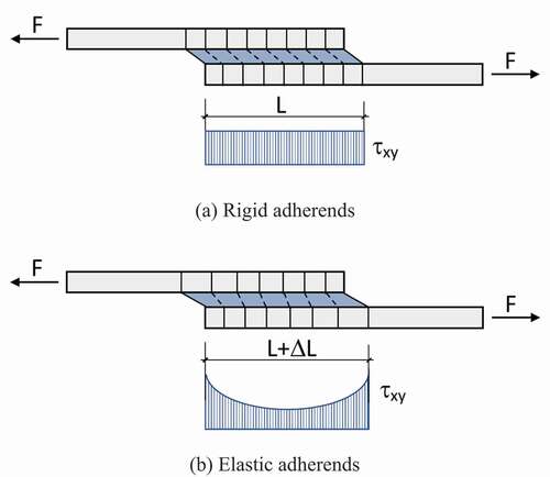
where F is the applied load, b is the joint width and L is the overlap length. The value of the shear stress computed via Equationequation 1(1)
(1) can be interpreted as the average shear stress acting on the adhesive layer. Although the modelling assumptions leading to Equationequation 1
(1)
(1) represent major simplifications of the actual system, they still provide the main guidance to evaluate the shear strength of adhesive joints in conformity to ASTM and ISO standards.
Volkersen’s analysis[Citation15] introduced the concept of differential shear, which is schematically illustrated in ). The assumption of pure shear deformation of the adhesive is maintained as in the simplest analysis, the adherends can deform in tension because they are considered elastic and not rigid. An effect that is not taken into account in this analysis is the bending moment due to the eccentric load path of SLJs. The solution is more representative of a Double Lap Joint (DLJs) than SLJs, since bending of the adherends in DLJs is not as significant as in SLJs.
The eccentric load path in a SLJ generates a bending moment and a transverse force at the ends of the joint, in addition to the applied tensile load per unit width. Because of this bending moment, the joint will rotate, altering the direction of the load line with the tendency of the applied tensile forces to come into line. As the joint rotates, the bending moment will decrease, giving rise to a nonlinear geometric problem where the effects of the large deflections of the adherends must be accounted for. The first to consider these effects were Goland and Reissner, [Citation16] whose analysis was later extended by Oplinger, [Citation40] who considered large deflections both outside and inside the overlap, as well as the individual deformation of the upper and lower adherends in the overlap. The results reported by Oplinger[Citation40] were close to those of Goland and Reissner[Citation16] in the case of large adherend-to-adhesive thickness ratio, whereas they differed significantly in the opposite limit of adherends thinner than the adhesive layer. Zhao[Citation41] developed a simpler form of the bending moment factor that is accurate for thick and stiff adherends but has limitations for short overlaps.
After the determination of the loads at the ends of the overlap, Goland and Reissner[Citation16] calculated the shear and peel stresses in the adhesive layer, solving a plane strain problem. Instead of solving a nonlinear geometric problem due to the eccentric load path, they solved a linear problem in the overlap with the loads applied at the ends. In this way, they avoided a more complex problem with the consideration of the geometric nonlinearity effect.
After the so-called classical works, some authors tried to obtain more general closed-form solutions by including, for example, adherends with dissimilar thickness and material properties or composite adherends .[Citation9–23−Citation25–53] However, as the models get more general, their mathematical structure become increasingly complicated, thus making the need for numerical methods more prominent, either to evaluate stress values from closed-form solutions, [Citation15,Citation16] or to compute an approximate solution of the governing differential equations.
Models of adequate fidelity are particularly necessary when the joints include laminated composite adherends, since through-thickness (or transverse) shear and normal deformations in the adherends can be hardly neglected. The most important of the earlier analyses to account for these deformations were done by Renton and Vinson, [Citation22] Srinivas[Citation23] and Allman .[Citation24] Due to the increase in use of composite materials at that time, Renton and Vinson[Citation21,Citation22] suggested that the analysis should consider not only the anisotropic properties of composites, but also the laminated construction (anisotropic properties of each lamina and lamina fibre orientation). Using composite laminated plate theory, they developed a linear elastic analysis between two similar or dissimilar laminated or isotropic adherends for a SLJ.
Wah[Citation17] was the first to consider laminated composite adherends that were symmetrical about their midsurface. The adhesive shear stress was assumed to be constant through the thickness whereas the adhesive peel stress could vary. The case of asymmetric composite adherends in balanced or unbalanced joints was considered more recently by Yang and Pang[Citation33] and Mortensen and Thomsen[Citation36] where the coupling effect of the external tensile loading and the bending moment due to the asymmetry of the composite laminates was considered.
Most analytical methods indicate that the strength of adhesive joints is enhanced by thicker bondlines (i.e. the stress decreases as the bondline thickness increases) as reported, for instance, in the study by Srinivas .[Citation23] However, in practice, the adhesive lap joint strength decreases as the glueline gets thicker. Adams and Peppiatt[Citation44] proposed that this seemingly contradictory behaviour could be understood as an effect of the presence of defects, such as voids and micro cracks, which are presumably more numerous per unit volume in thicker bondlines. Other possible reasons for decreasing strength in thicker bondlines might be identified in the more pronounced adherend bending due to load misalignment, or interface adhesive-adherend stresses .[Citation45,Citation46] Therefore, in order to realistically predict failure loads, analytical models should include the variation of stress through the adhesive thickness, including the interface stresses.
When adhesives having a large plastic strain to failure are used, such as rubber-modified epoxies, the adhesive plasticity must be included in order to correctly simulate the stress and strain distributions when the adhesive yields. Adherends can yield too, and the analysis needs to account for this behaviour if realistic failure loads are to be predicted. One of the most important works considering adhesive plasticity was done by Hart-Smith for SLJs[Citation18] and DLJs .[Citation19] Material nonlinearity due to plastic behaviour is not often included because of the increased complexity in the mathematical formulation and the need to resort to numerical methods (typically, FEA), for a solution. Only three analyses were found in the literature on analytical models that considered both adherend and adhesive nonlinear behaviour .[Citation20,Citation30,Citation38]
3. Process zone methods
In engineering applications, the presence of stress concentrations (also known as hot-spots) in design of adhesively bonded structures is almost unavoidable .[Citation47] These hot-spots can be generated from geometrical features (e.g. notches, holes, corners, edges) that are inherent characteristics on the construction of components .[Citation48] However, in the modelling of adhesive joints the consideration of only the peak (i.e. maximum) value of stress (or strain) in such hot spots, have been shown to produce over-conservative predictions .[Citation49]
Therefore, based on the concept that failure takes place within a process zone, process zone models (i.e. averaging methods) have been developed to address the effect of stress concentration on the mechanical behaviour of materials .[Citation50] This approach takes into consideration that fracture involving crack initiation and propagation is strongly influenced by aspects of the stress (or strain) field within the process zone, such as the gradient of stress, or the absolute volume of material under high stress.
The increasing use of process zone models is closely related to the evolution of computer-aided simulation (e.g. Finite Element Analysis – FEA), which made the calculation of stress very straightforward even for complex structures .[Citation51] In this regard, the use of standard FEA techniques, which do not require special purpose elements, is especially interesting for large scale models in industrial applications .[Citation52] These techniques employ standard elements (e.g. continuum elements) to accurately calculate the distribution of stress in bonded joints by considering, for instance, kinematic constraints between adhesive and adherends .[Citation53]
Another advantage of process zone methods is their ability to circumvent issues related to the high dependency of the mesh size when considering maximum value criteria, as well as capability to deal with singularities (e.g. overlap ends of single-lap joints) .[Citation12] Process zone methods have been investigated since the 50′s (e.g. Neuber[Citation54] and Peterson[Citation55]) and were brought back in the recent years by Taylor .[Citation56]
Process zone methods rely on a length parameter (i.e. critical distance) which defines the size of the zone (as shown in ). This process length can be defined using calibration techniques, as done by Hoey et al., [Citation57] a technique that has been already validated for adhesives in fatigue conditions by Beber et al.[Citation58]
Figure 2. Theory of critical distances: (a) Point method, (b) Line method.
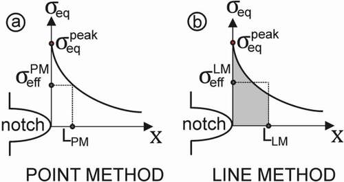
Then, the defined failure criterion (stress or strain) can be considered as an average value in a point, in a line, in an area or in a volume .[Citation59] For instance, by averaging an equivalent stress within a critical distance L, an effective stress
is obtained which can be used for prediction purposes, as illustrated in .
The TCD comprises several methods that consider the averaged stress in a point, in a line, in an area or in a volume. The TCD has been applied to material such as metals, ceramics, polymers (including adhesives) considering both linear-elastic, as well as plastic behaviour .[Citation59] In the Point Method () the effective stress is postulated to be the equivalent stress at a point determined by a critical distance (
from the singularity (or notch), that is:
In the Line Method (), the effective stress is considered to be the equivalent stress averaged in a line with a length determined by a critical distance (
) from the notch:
On the other hand, Zhao et al.[Citation60] considered the adhesive thickness as the distance over which the maximum stresses are averaged and then compared to the adhesive yield strength. Clark and Mcgregor[Citation61] established that for the failure to take place the maximum principal stress must exceed the ultimate tensile stress of the adhesive within a finite process zone. Three joints types, namely single-lap, double strap and T-peel joints were used to demonstrate that length of such zone was independent of the joint geometry. Critical strain at a distance was used by Towse et al.[Citation62] as failure criterion the critical strain at a distance to predict the behaviour of double-lap joints. Authors have applied a nonlinear analysis, which included the effect of residual thermal stresses.
Regarding the static failure of adhesively bonded joints, Crocombe[Citation63] applied a stress criterion based on an averaging method in order to predict the failure load of single-lap joints considering a linear-elastic material behaviour obtaining good predictions for ductile adhesives. Critical longitudinal strain method has been employed for single lap joints to successfully predict the effect of overlap length and substrate thickness (Khoramishad et al.[Citation64]), bondline thickness (Akhavan-Safar et al.[Citation65]), and dissimilar adherends (Cruz et al.[Citation66]).
For the fatigue of adhesives, Schneider et al.[Citation67] used the maximum principal stress to predict the lifetime of scarf, thick adherend and single lap joints at different temperatures using a linear-elastic material model. Beber et al. extended this analysis to include elasto-plastic material models, [Citation68] as well as to consider multiaxial stress response .[Citation69] These considerations were able to improve the quality of predictions, especially for SLJs. Schmidt et al.[Citation70] performed a reliable fatigue strength assessment of adhesively bonded thin‐walled steel structures taking into account both point and line averaging methods.
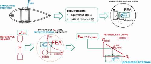
A practical example of a lifetime prediction carried out using a process zone method based on the critical distance is presented in . The objective is to predict the lifetime associated with an operational load . A requirement that should be previously defined is the equivalent stress (e.g. maximum principal) and the critical distance L. Based on the operational load, the effective stress is calculated
. Considering a reference sample, which SN curve is be used for definition of the lifetime prediction, a reference force
that causes the same effective stress is obtained from a simulation. From the reference force a stress amplitude is calculated, which is then finally correlated with a predicted lifetime that corresponds the lifetime on the sample to be predicted.
Figure 3. Application of the process zone method based on the use of the critical distance for lifetime prediction of adhesive bonded joints.
Beber et al.[Citation58] succesfully carried out critical distance-based fatigue lifetime predictions of three notched bulk specimens and a single-lap joint considering the Drucker-Prager equivalent stress as failure criterion. More recently, Sousa et al.[Citation71] have employed a process zone method based on an equivalent notch approach to consider mixed mode loading for the prediction of single-lap joints.
4. Linear elastic fracture mechanics
Linear Elastic Fracture Mechanics (LEFM) is a basic theory of fracture, originally proposed by Griffith[Citation72] and further developed by Irwin[Citation73] and Rice .[Citation74] This method is used to predict the critical load that leads to the propagation of an existing crack under a static load or the crack growth rate under cyclic loadings. It can be applied when the material behaves in a linear-elastic manner and the fracture process zone is included in the singularity region around the crack tip. In other cases, elastic-plastic fracture mechanics or Cohesive Zone Models can be used to describe the fracture behaviour.
The fundamental problem of the Griffith’s theory is shown in . In this case, the critical remote stress leading to the unstable growth of a crack with a length 2a within an infinite plate can be calculated as:
Figure 4. Fundamental problem of the Griffith’s theory – a crack in a plate under tension.
where GIc is the mode I critical Energy Release Rate (ERR) and E is the Young’s modulus.
In a more general formulation, the crack propagation under a quasi-static load occurs when the ERR, G, is higher than a critical value Gc:
where Πp is the total potential energy of the body and the crack area. In general, the total ERR is the sum of mode I, II and III contributions, and its critical value depends on the mode mixity (ratio between single components).
After the work by Williams, [Citation75] the LEFM was extended to interface cracks, so that is could be adopted for predicting, for instance, the propagation of cracks in bonded connections. The complete stress fields in the neighbourhood of an interface crack tip were presented by Rice, [Citation74] showing that the singular behaviour with an exponent equal to −0.5 is preserved, even if a logarithmic term appears, thus generating oscillatory stress fields in the close vicinity of the tip. This leads to difficulties in the determination of the mode I and II components of the Stress Intensity Factors or the ERR (Rice,[Citation74]). Indeed, the mode decomposition, and therefore the values of GI and GII, are not univocally defined but depend on the reference length adopted for their calculation. Therefore, special care has to be taken when the ERR components are calculated through the Virtual Crack Closure Technique, VCCT (see the next section), as they depend on the adopted element size.
In addition, the theoretical displacement fields are characterised by an unrealistic crack face compenetration in the close vicinity of the tip. It was shown that in several conditions such feature is confined within a region with a negligible extension, so that the LEFM framework proposed by Rice[Citation76] remains applicable. On the other hand, when the compenetration zone is more extended, the LEFM can still be adopted, according to the framework proposed by Comninou .[Citation77]
As a further complication, the critical value of the ERR and the Paris-like law for the fatigue crack propagation are strongly dependant on the ratio between the mode I and II components, generally with a higher resistance to crack propagation as a pure mode II condition is approached (see, for instance, Wang[Citation78]; Ducept et al.[Citation79]; Carraro et al.[Citation80]; Adamos et al.[Citation81]). Several models were proposed in the literature for assessing the critical ERR or the Paris-like law in mixed mode conditions. For instance, the critical ERR can be estimated from the simple phenomenological expression proposed by Hutchinson and Suo[Citation82] or Ducept et al., [Citation79] or with the damage-based model by Wang, [Citation78] or with the analytical model by Adamos et al. .[Citation81]
Under fatigue loading, the crack propagation in bonded joints was sometimes shown to be well predicted by using only the mode I component of ERR and the relevant Paris-like law obtained through a pure mode I test (Kinloch and Osiyemi[Citation83]; Abdel Wahab et al.[Citation84]; Rocha et al.[Citation85]). Other authors made use of empirical expressions for defining an “effective” or “equivalent” ERR, incorporating the mode mixity, to be used in the Paris-like law for predicting the fatigue crack growth (Cheuk et al.[Citation86]; Quaresimin and Ricotta[Citation87]). A model, valid both for static and fatigue loading, was proposed by Carraro et al.[Citation88] based on the crack propagation mechanisms observed in composite bonded joints. The proposed criterion uses the only mode I ERR when the loading condition is mode I-dominated, and local stress parameter, derived from the maximum principal stress field in the adhesive, when the loading mode is shear-dominated. This last criterion, however, cannot be fully ascribed to the LEFM framework, as the stress parameter is calculated within a process zone that may extend beyond the singularity region.
Despite the mentioned complexities and difficulties, the LEFM was successfully applied to predict the crack propagation in bonded connections (see, for instance, some of the applications listed in the next section, as the VCCT technique is often adopted for the calculation of the ERR).
Special care must be taken when using the LEFM approach in bonded joints. Indeed, the fracture process zone can overcome the singularity region, leading to a significant dependence of the critical ERR on the adhesive thickness, under mode I and, mainly, mode II loadings (Ji et al., [Citation89,Citation90] Sarrado et al.[Citation91]). In these conditions, other approaches, such as the Cohesive Zone Model described later in the paper, can be applied, even if it requires a higher computational effort (Rabinovitch[Citation92]).
As a final remark, it can be said that LEFM can be adopted to predict the static or fatigue crack propagation in bonded joints, provided that the fracture process zone is small, which is typically the case when the adhesive is sufficiently brittle (Sun et al.[Citation93]). Critical ERR or Paris-like curves are preferably obtained on joints with the same adhesive thickness as the joint to be designed or verified. Crack initiation falls outside the scope of LEFM, hence that phenomenon cannot be accounted for by this method.
It should be emphasized that, despite its important advantage – simplicity and fast calculations, LEFM presents also some significant disadvantages. The idealizations inherent to the method limit its potential to analyse problems encountered in industrial practice. The method is only suitable for materials with linear elastic characteristics. Furthermore, the assumption of pre-existing cracks is crucial for LEFM, which excludes some types of cracks from the analysis (e.g., very small cracks).
The main challenges of the LEFM methods can be summarized as follows:
to develop numerical tools for the fast computation of the SIF and ERR for interface cracks, with free and coarse mesh suitable to be applied to big structures;
to define standardised testing procedures for the mode III properties, useful in practical applications;
to model the influence of the adhesive thickness on the fracture toughness.
5. Virtual Crack Closure Technique (VCCT)
Virtual Crack Closure Technique (VCCT) is a linear elastic fracture mechanics-based method used to compute the strain energy release rate based on 2D and solid 3D FEA which provide the mode separation required when using the mixed-mode fracture criterion. The method has been developed by Rybicki and Kanninen[Citation94] and detailed by Krueger .[Citation95]
The VCCT method is based on the assumption that, when a crack grows, the energy released balances the work needed to close to crack to its initial length before propagation. The key input parameters of the method are the critical mode-I strain energy release rate GIC and critical mode-II strain energy release rate GIIC, which have to be determined experimentally. The VCCT method is usually applied through the FE method.
In the three-dimensional VCCT model, three stress intensity factors (SIF) are calculated using the following equation:
where is the energy release rate in mode i,
the stress intensity factor for mode i,
the elastic modulus,
for plane stress and
for plane strain whereas
is the Poisson ratio. Thus, either for 2-dimensional or 3-dimensional problems, the previous equation for a crack extension Δc may be expressed as:
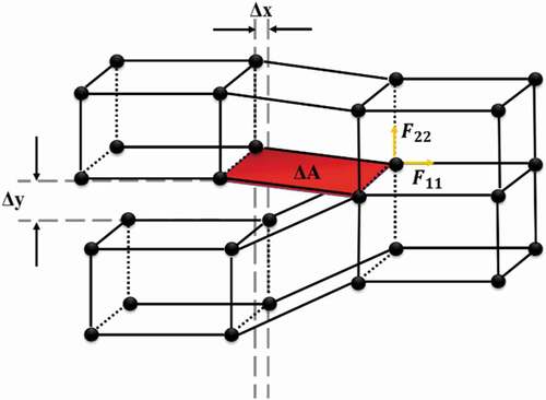
where GI, GII, GIII the energy release rates in mode I, II and III respectively, F11, F22 and F33 the corresponding reaction forces on the crack tip and Δx, Δy and Δz the relative displacements between the upper and lower nodes of the crack as shown in . In the particular case of the absence of one of the three modes, the corresponding equation may be neglected. Nevertheless, by using the VCCT method the corresponding Gi values should be imposed.
Figure 5. Schematic illustration of the concept of the VCCT method.
In the last decade, VCCT method has been implemented into commercial FE codes such as ANSYS and Abaqus. Initially, the method has been widely used to simulate delamination growth in CFRP composites[Citation95] and in the last decade it has found many applications to adhesive joints together with the Cohesive Zone Modelling method.
A short description of some representative works showing the evolution of VCCT in bonded joints follows.
Jokkinen et al.[Citation96] have studied the applicability of VCCT for crack growth analysis of an adhesively bonded joint with a ductile adhesive and self-similar crack growth. The analysis was performed on a Double Cantilever Beam (DCB) specimen with epoxy adhesive. First, a linear elastic behaviour was assumed for the adhesive and in the next step, a nonlinear analysis was performed by using a linear elastic – ideally plastic material model. For both approaches, the numerical results match well the experimental curves.
Senthil et al.[Citation97] used the VCCT method to ascertain the effective load carrying capacity of the adhesively bonded composite joints in the presence of closed debonds (defects). For the study, they used two adhesively bonded symmetric flat rectangular laminates of identical size in length and width having closed (embedded) debond of square shape at the specimen centre subjected to a uniform in-plane end-shortening. The authors investigated the influence of parameters such as laminate sequence, debond location, size and its shapes (square and circular).
Quaresimin and Ricotta[Citation87,Citation98] developed a model for predicting the fatigue life of bonded joints, based on the distinction between a crack initiation and propagation phase. They used the VCCT, combined with a Paris-like curve linking the ERR to the crack growth rate, for predicting the life spent for the debond propagation in composite single lap joints, resulting in a sound agreement with experimental results.
Pirondi et al.[Citation99] developed a fatigue VCCT model based on the Direct Cyclic procedure of the Abaqus FE code. The model has been successfully applied to the DCB, ENF, and SLJ specimens and the results are in the form of crack length vs. number of cycles and G vs. crack length. The authors have also compared the fatigue VCCT model with a fatigue CZM model and have found that (a) the two models are in overall good agreement with each other, with the exception of the first instants of propagation where the CZM process zone has to shape up, whereas the VCCT starts with a sharp crack and (b) while the modelling effort is a bit higher (need of introducing a layer of cohesive elements), the CZM is easier to use (no need to identify the proper number of Fourier terms and time increment to represent cyclic loading). At the same time, it results more efficient as the computation is lower up to one order of magnitude, despite the less performing hardware used to run the analyses.
Many authors have combined the VCCT method with the CZM method. Jokinen et al.[Citation100] developed a method for modelling the fracture process with separate nucleation and propagation phases by combining the VCCT with the CZM on the finite element basis to take into account the development of fracture toughness. The method was applied to simulate a double cantilever beam (DCB) test as an example. The analysis focused on the physical validity of the VCCT-CZM coupling and on the determination of simulation parameter values. By using experimental data as a reference, the simulation results were compared to the results of traditional CZM and VCCT simulations. The comparison indicated that the combined CZM-VCCT method reproduced the DCB test cycles more accurately than the separate application of CZM and VCCT models.
Finally, recently, De Carvalho et al.[Citation101] have proposed a modelling approach to simulate delamination propagation in fatigue that combines VCCT with a progressive nodal release strategy. The progressive nodal release alleviates the artificial stress concentrations found when using the VCCT with instantaneous release to model 3D delamination without re-meshing. This enables crack shapes that do not conform to the underlying mesh to be readily simulated. Contrarily to previous implementations, the local delamination propagation direction is not assumed to follow mesh lines, but it is instead computed as part of the iterative procedure proposed to determine the maximum energy release along the crack front. The results suggest that VCCT can accurately simulate Mode I, Mixed Mode I/II and Mode II fatigue delamination growth and be used to simulate growth of arbitrarily shaped cracks that do not conform to the underlying mesh. The new approach can be potentially used to simulate fatigue debonding propagation in bonded joints.
The existing literature suggests that the VCCT is an efficient method to simulate debonding growth in bonded joints under static and fatigue loads. Of course, it has certain advantages and disadvantages and its implementation on the FE method is constantly improving. Overall, it stands below the CZM method.
In, [Citation102] Floros and Tserpes, have compared the VCCT method with the CZM method in simulating debonding growth in a crack lap shear composite bonded joint containing a bolt as a crack stopper (). They have found that the VCCT method is more capable than the CZM method in simulating sudden debonding.
Figure 6. (a) Geometry and boundary conditions of the crack-lap shear bonded/bolted specimen, [Citation102] (b) Comparison of load-displacement curves predicted using the VCCT and CZM methods, [Citation102] (c) Comparison of debonding growth simulated using the VCCT and CZM methods[Citation102]
![Figure 6. (a) Geometry and boundary conditions of the crack-lap shear bonded/bolted specimen, [Citation102] (b) Comparison of load-displacement curves predicted using the VCCT and CZM methods, [Citation102] (c) Comparison of debonding growth simulated using the VCCT and CZM methods[Citation102]](/cms/asset/6a0c6a60-f09f-4f39-b37d-1a55a5c5a95e/gadh_a_1941903_f0006_oc.jpg)
6. Stress singularity approach
Adhesive bonding between dissimilar (or equal) materials gives rise to points where geometry and material properties change abruptly, which makes the stress state at these points unbounded from a linear elastic point of view. Examples of critical points of stress singularities in a double-lap shear joint are shown in . Therefore, the use of failure initiation criteria based on nominal stresses is not a viable strategy to predict failure, whereas the use of singularity parameters to characterize the stress state is a feasible alternative, which is consistent with the principles of Linear Elastic Fracture Mechanics.
Figure 7. Examples of critical points where stress singularities appear at an adhesive joint.
A comprehensive review of the existing literature on stress singularities and prediction of failure initiation in adhesive joints falls beyond the scope of the present work. The main features of the method will be illustrated here as well as an historical perspective on its development.
From the pioneering works appeared in the early 20th century, where the analytical solutions of 2-dimensional elasticity problems with stress singularities were first derived, (e.g. Wieghardt, [Citation103] Williams[Citation104]), many advances have been made and published in this area.
One of the first classical attempts to use the singular stress state as the driving force to study the propagation of a crack running along the adhesive interface is due to Malyshev and Salganik, [Citation105] who assumed an initial crack emanating from the corner at one end of the overlap length, and did not address the initiation of failure.
Two classical works, covering the analysis of the singular stress state without assuming a pre-existing crack or failure in bimaterial corners were studied by Bogy and Wang[Citation106] and Hein and Erdogan .[Citation107] It is important to notice that there are two clearly separated states, nucleation or initiation of the crack/failure, and the crack progression until the catastrophic failure.
Dempsey and Sinclair[Citation108] described in detail all types of stress singularities in 2D elasticity problems while a rigorous mathematical analysis of these solutions can be found in Nicaise and Sändig .[Citation109] In this scheme, and taking a polar coordinate system centred at the corner tip, the stresses admit, in the vast majority of cases, variable separation in the polar coordinates (r,), which results in the following decomposition of the stress tensor:
where, Kn (n= 1, …, N) are the Generalized Stress Intensity Factors (GSIFs), λn are the order of stress singularities, and fij() is the characteristic angular function for stresses. The prefix “Generalized” refers to a Stress Intensity Factor which is associated to a singularity stress field different from that of a crack. While the order of stress singularities λn and the characteristic angular function fij(
) only depend on the local geometry, local boundary conditions and the mechanical properties of the materials in the corner, the Generalized Stress Intensity Factors Kn depend on the global geometry and far field loading conditions of the problem. The quantities λn and fij(
) can be obtained using analytical or semianalytical procedures, while the calculation of Kn requires detailed numerical methods, such as the Finite Element (or Boundary Element) Analysis. Alternatively, GSIFs can also be estimated from experimental data.
Very few particular configurations give rise to pure logarithmic stress singularities as pointed out by Sinclair .[Citation110]
One of the first proposals to predict the failure initiation in adhesive joints, without assuming a pre-existing crack is due to Gradin and Groth, [Citation111] who defined a generalized stress intensity factor and compared it with a critical allowable value (the so-called generalized toughness) for the failure to initiate, as proposed in an analogous way by Hattori et al .[Citation112]
The growing adoption of composite materials, mainly in aeronautic lightweight structures, and the use of adhesive bonding with other materials complicate the analytical modelling of these singularity stress fields. Ting[Citation113] made a relevant contribution to the analysis of multi-material corners with the presence of anisotropic materials, which enabled the detailed study of joints with composite materials.
A recent comprehensive review of the mathematical aspects and practical applications of the singularity stress characterization in joints with anisotropic materials (including composites), has been presented by Mantič et al.[Citation114] Besides the overview of more than 120 reference on the topic, the authors introduced a failure criterion based on the singularity parameters of the stress state, together with corroborating experimental evidence.
The stress singularity approach has also been experimentally validated in the study of fatigue crack initiation (Lefebvre et al.[Citation115]), and fatigue strength in metallic bonded lap joints, Imanaka et al.[Citation116] Fatigue crack initiation in composite single lap joints was investigated by Quaresimin and Ricotta[Citation87] and Meneghetti et al., [Citation117] thus proving the capability of the method to predict the effect of the overlap length.
Depending on the particular geometry of the corner and the elastic properties of the materials, the values of the orders of stress singularities λn vary between 0 (to make the stress singular) and 1 (to remain the strain energy with a finite value), and consequently, the dimensions of the GSIF vary accordingly. In many studies, a proper definition of the structure of the stress field is done by taking a characteristic length (L0) to the power of the order of stress singularity in the denominator, equal than of the radial distance, so that the GSIF always has the same units as the stress. In any case, an appropriate definition of the GSIF is needed in the different corner configurations, to standardize its definition and to allow comparisons between different studies. A good example of this, can be found in Hwu and Kuo.[Citation118]
The use of singularity stresses to predict the failure of adhesively bonded joints is still the subject of intense research efforts. Examples of recent developments include the extension of analytical solutions to three-dimensional problems with anisotropic materials, (Ren et al [Citation119] , Zappalorto et al.[Citation120]), which is quite useful to analyse joints with thick composite laminates as adherents. There are also applications in joints where adhesives with dissimilar stiffness are used along the overlap length in order to make the shear stress distribution more uniform and maximize the failure load of the joint (Breto et al.[Citation121]), and procedures to determine the critical value of the stress intensity factors[Citation122] in adhesive joints with stress singularities.
Singularity stress states influence the occurrence of premature failure in many problems, as well as in many standard test configurations, as pointed out recently by Barroso et al, [Citation123] where at least three typical tests in composite materials with adhesives show significant higher failure loads after removing the local configuration which gives rise to the stress singularity. The excellent correlation between the predictions and the experimental evidence establishes confidence in the method.
The main advantage of this approach is the detailed and accurate knowledge of the local stress field at the corner tip, with analytical, or semi-analytical calculations for the key singular parameters of the stress representation, and with the knowledge of the contribution of each term in the stress decomposition defined in Equationequation 10(10)
(10) .
The main drawback of the stress singularity approach is the inherent complexity of the calculations required to derive the singularity parameters of the stress field, that is the order of stress singularities and the angular shape functions. The good accuracy achieved with existing computational tools in problems which involve isotropic materials, is no longer preserved in presence of anisotropy. Another inconvenience of this approach is the lack of standardized tests for the experimental determination of the critical GSIF value (Generalized Toughness) for a general corner configuration.
Additional aspects, such as the influence of local plasticity, local three-dimensional effects, or stress relaxation, have also been addressed in literature, although, as mentioned before, it is not the aim of this work to cover all these issues in detail, and just to make an overview of the approach.
Due to its nature, with the presence of predicted unbounded stresses, the Stress Singularity approach shows its full potential mainly in problems with no plasticity effects (fatigue problems with low load levels, or simply brittle materials). The great advantage is the explicit knowledge of the local stress field, whereas its main drawback is the complexity in the evaluation of the singularity parameters defining the stress state.
7. Finite fracture mechanics
Finite Fracture Mechanics (FFM) is a mathematical framework designed to predict crack initiation in presence of stress concentrations. It was first introduced in the pioneering work of Leguillon et al.[Citation124] for homogeneous and isotropic notched plates, and it has received considerable attention in the last two decades. FFM is based on the idea that failure does not initiate at a single point through the generation of a crack of infinitesimal length, but rather with the formation of a finite-size crack appears, characterized by a length ac and a critical load, Pc, which are both unknowns of the problem. In the context of bonded joints, the principles of FFM can be illustrated by considering a bi-material corner as in ), with a remote applied load P. Crack initiation occurs with a finite crack length, ac, when the load reaches its critical value Pc, as shown in ).
Figure 8. Bi-material corner a) before and b) after the initiation of a finite crack.
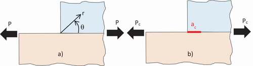
These two unknowns (ac,Pc) can be calculated by imposing the following two conditions: a stress-based failure criterion, which requires that the stress in the pristine configuration, along the crack initiation length ac, is at least equal to the material strength, and the energy criterion, which dictates that the released potential energy balances the energy required for the formation of new crack surfaces. These two constraints can be formally expressed as the following system of equations:
In Equationequations 11(11)
(11) (stress-based failure criterion) and 12 (energy criterion),
are the normal and shear interface stress components,
are the normal and shear interface strengths,
is the elastic potential energy, A is the crack area and
is the critical total Energy Rate Release (ERR), which is typically a function of the mode mixity,
. It is worth highlighting that the symbol
is adopted in the energy criterion, instead of δ as in the classical fracture mechanics, meaning that a finite energy amount is released in correspondence of a finite crack area increment
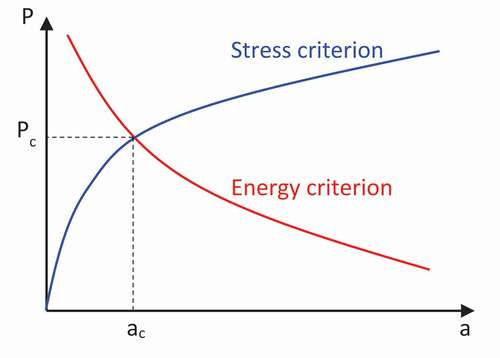
. A typical qualitative plot of the critical load estimated by the two criteria against the initial crack length is shown in . The intersection of the two curves represents the solution of the system and identifies the crack initiation condition.
Figure 9. Qualitative plot of the stress and energy criteria.
The FFM approach was first applied to bonded joints by Leguillon et al.[Citation125] The case study consisted of a joint with steel adherends, bonded through an epoxy adhesive. Two strategies were adopted by the authors to predict the load at crack initiation: a macro-scale and a micro-scale approach. In the macro-scale approach, the existence of the bond-line was neglected, and the specimen was treated as a homogeneous steel plate with a sharp notch with an opening angle of 90° (square edge joint). In the micro-scale approach, instead, the steel/epoxy bi-material corner was considered. In both cases, the singular local stress fields and the ERR were calculated theoretically through an asymptotic expansion. A similar accuracy in the prediction of crack initiation load was obtained with the two methods, even if the micro-scale approach was the only one that could, in principle, describe the influence of the local geometry, such as the actual corner angle and the adhesive thickness. The micro-scale approach is also more complicated due to the complex nature of the stress fields in the presence of bi-material interface cracks (Rice[Citation74,Citation76]).
Later, Garcia and Leguillon[Citation126] formalised the FFM approach for bonded connections between isotropic adherends made of the same material, with a generic corner angle. They used a multiaxial failure criterion (in the stress criterion) and a mode-dependency formulation for the fracture toughness (in the energy criterion). The macro-scale methodology was implicitly adopted, and the asymptotic expansion approach was used for the calculation of the singular stress fields.
Tran et al.[Citation127] adopted a similar macro-scale approach to predict the failure load of PC/epoxy/PC and PMMA/epoxy/PMMA joints, thus quantifying the influence of the corner angle with good accuracy.
Cornetti et al.[Citation128] and Weißgraeber and Becker[Citation129] used the FFM together with the Weak Interface (WI) approach for predicting crack initiation in concrete/composite and metallic bonded joints, respectively. In the WI approach, the bond-line is described as a bed of normal and shear springs, which makes the calculation of the pristine stress fields and the ERR particularly simple from an analytical point of view, even if the stress singularity in the presence of sharp corners is not accounted for. The proposed methodology was shown to be capable of describing the effect of the overlap length and the adhesive thickness in lap joints (Weißgraeber and Becker[Citation129]). As a further note, the effect of the local corner geometry (opening angle) cannot not be correctly captured with this approach due to the limitations of the simplified stress analysis.
Moradi et al.[Citation130] proposed a numerical procedure based on the FFM, in which the stress fields and the total ERR were calculated through FE analyses. The case of steel/epoxy/steel single lap joints was considered. The stress criterion involved the interface peel stress only and no mode dependency was considered for the critical ERR in the energy criterion. The approach captured the effect of the adhesive thickness and was also proved to capture the detrimental effect of the increasing adhesive Young modulus on the crack initiation load.
A similar approach was adopted by Mendoza-Navarro et al., [Citation131] with the difference that both the peel and shear stresses were included in the stress criterion. The effects of the overlap length and multiaxial loads was correctly captured for steel/polyester resin/steel joints.
Later, Hell et al[Citation132] proposed a similar numerical procedure including also the possibility of crack initiation inside the adhesive, not at the interface. They applied the model to steel single lap joints, obtaining a good agreement with experimental results with different overlap length and adhesive thickness. Both the peel and the shear stresses were involved in the stress criterion and the mode dependency of the critical ERR was also considered.
Le Pavic et al.[Citation133] applied the FFM approach to aluminium joints tested through an Arcan fixture with different loading angles. They used both a simple analytical expression (as those adopted by Weißgraeber and Becker[Citation129]) and FE computations for the stress fields and the ERR. FEA showed very good correlation with experimental data, while the analytical method turned out to be more conservative, albeit much faster in its application.
Carrere et al.[Citation134] made a very interesting comparison between the FFM approach and a Continuum Damage Model (CDM), applied to steel single lap joints. Both the FFM and the CDM can be classified as coupled criteria, in the sense that both the interface strength and fracture toughness determine the structural failure. The difference is that, in the FFM the stress and energy criteria need to be simultaneously satisfied for the initiation of a finite size crack. Differently, in the CDM the satisfaction of the stress criterion triggers the degradation of a finite element, culminating in its suppression driven by the ERR. The two approaches provided quantitatively similar results when the CDM was used in combination with small-displacement FE simulations, which led to an underestimation of the experimental failure load. Although the two methods show a similar capacity to predict the occurrence of failure in bonded connections, FFM is more straightforward and more conservative than CDM. A drawback of FFM with respect to CDM is that the crack location has to be known a priori. The greater flexibility of CDM has, however, to be weighed against the higher computational cost of this method, due to the finer discretization of the adhesive layer (at least 20 elements).
All the examples reported so far considered 2D problems, which can be considered acceptable for simple geometries such as single or double lap joints. An extension of the FFM to 3D problems was formulated by Doitran and Leguillon .[Citation135,Citation136] The stress fields and the ERR were calculated by FE analyses and the shape of the interface crack was chosen based on the iso-stress contour lines obtained from the analysis of the joint in the pristine condition. The 3D formulation was shown to slightly improve the failure predictions for scarf joints (Doitran and Leguillon[Citation136]).
To conclude, the FFM approach, initially conceived for homogeneous notched plates, proved to be a very useful tool for predicting the failure (meant as crack initiation) of bonded joints. The following main conclusions can be drawn:
in principle, FFM makes possible to model the effect of the joint geometry, adhesive thickness, corner angle, material elastic properties and multiaxial loads in the prediction of the failure load;
a macro-scale (i.e., neglecting the adhesive layer) or a micro-scale (considering the adhesive layer) approach can be adopted, the latter one being the only method to assess the influence of the adhesive thickness and tensile modulus, as well as the local corner shape;
FFM requires the knowledge of the stress fields in the pristine configuration and the ERR for a crack initiated at the bi-material corner. They can be calculated analytically (through an asymptotic expansion of the singular stress fields or through simplified formulations), or numerically. Using the asymptotic expansion of the stress field or FEA with very fine local meshes are the only possibilities to account for the local corner geometry;
the interface strength and fracture toughness need to be known. Standardised procedures can be found for measuring the interface toughness, whereas characterising the strength is more complicated because of the singular nature of the stress fields at a bi-material interface. A procedure was however proposed by Lauke and Barroso[Citation137] and Barroso et al.[Citation138];
multiaxial failure criteria and mode-dependency formulations should be adopted in the stress and energy criteria, respectively;
FFM can be applied to quasi-static loads only and it enables the evaluation of the crack initiation load, whereas it cannot predict the ultimate joint failure.
On the basis of these considerations, FFM results to be a very useful tool to make comparative and preliminary analysis based on plausible assumptions on interface properties, and to define optimal solutions in terms of geometry, constituents and loading conditions. The approach can be implemented in FE codes, even if the very fine meshes required for the computation of the stress fields and the ERR hinders its application to large structures, a limitation which can be circumvented by means of sub-modelling techniques.
As a last observation, to the best of the authors’ knowledge, no application of the FFM to composite bonded joints has been reported in the literature. Therefore, the potential of FFM to analyse composite bonded joints remains to be explored.
The main challenges of the FFM method can be summarized as follows:
to assess the experimental standard procedures to obtain the input interface properties, and particularly, the interface strength;
to investigate possible extensions of the method to the case of fatigue loading.
8. The cohesive zone method
8.1. Theory and application
Cohesive Zone Modelling (CZM) is a damage mechanics-based numerical approach suitable for modelling crack initiation and propagation. CZM is based on the works of Barenblatt[Citation139,Citation140] and Dugdale[Citation141] in the late 1950s/early 1960s, when the idea of a cohesion zone in front of the top of a crack was proposed. Later, in 1976, it was numerically implemented by Hilleborg et al.[Citation142] and a numerical model which defines a function between traction and crack separation was proposed. Needleman[Citation143] proposed various polynomial and exponential functions for the definition of traction-separation law. Typical bi-linear traction-separation laws for mixed-mode load analyses are shown in , where , are the ultimate relative displacements,
are the damage initiation relative displacements,
are the ultimate relative displacements and
is the “mode mixity”, which correlates ultimate normal and tangential relative displacements as can be seen in the small hatched triangle in .
and
subscripts stand for normal and tangential direction, respectively Additionally,
are the peak tractions in normal and tangential direction. Additionally, the area under the triangle for Mode I and Mode II is the critical energy release rate of the joint.
Figure 10. The bi-linear traction separation laws for a Mixed-Mode loading analysis[Citation144].
![Figure 10. The bi-linear traction separation laws for a Mixed-Mode loading analysis[Citation144].](/cms/asset/eb9825f6-9590-48a6-ba0e-2b7ad98f7fc8/gadh_a_1941903_f0010_b.gif)
During the last decades CZM has evolved and it has eventually achieved the status of method of choice for simulating delamination of composite materials and onset and debonding growth of adhesive joints. The method can be implemented either through spring elements[Citation145,Citation146] or by using cohesive elements between the adherends in 2-D[Citation147] or 3-D problems .[Citation148] The main reason for the wide acceptance of this method is its accessibility through the most common commercial Finite Element (FE) platforms and its capacity to be used in complex geometries.
CZM is based on the assumption that one or multiple interfaces can be artificially introduced in structures. Damage growth at these interfaces is modelled by the introduction of a discontinuity in the displacement field .[Citation149] As mentioned, the method is applied through traction-separation laws which can have various forms such as triangular, [Citation150] linear-parabolic, [Citation151] polynomial, [Citation152] exponential[Citation153] and trapezoidal .[Citation154]
CZM approach has been successfully used by numerous authors for the simulation of delamination of CFRP materials as well as the debonding initiation and growth of joints with metal and/or composite adherents. Dias et al.[Citation155] applied CZM for simulating Mode I loading in a DCB specimen. De Moura et al.[Citation156] studied Mode II loading by means of experiments and numerical models, by applying a trapezoidal traction-separation law. Campilho et al.[Citation157] investigated the influence of the input parameters and the form of the traction-separation law. Alvarez et al.[Citation158] applied CZM approach for simulating DCB configuration and examine the CZM parameters’ sensitivity. As can be seen in ), numerical, analytical, and experimental results are in good agreement. Furthermore, Floros et al.[Citation144] performed an experimental study and numerical simulations using CZM approach to simulate Mode I, Mode II and Mixed Mode I+ II loading of composite bonded joints. ) depicts the comparison of the load-displacement curve of the DCB specimen predicted by the CZM method with the respective experimental curves. As can be seen, the CZM method predicts accurately the debonding behavior of the DCB composite bonded joints, except for the regions where unstable debonding growth occurred during the tests.
Figure 11. Comparison between numerical (CZM) and experimental load-displacement curves obtained for DCB specimens (a)[Citation158] (b)[Citation144].
![Figure 11. Comparison between numerical (CZM) and experimental load-displacement curves obtained for DCB specimens (a)[Citation158] (b)[Citation144].](/cms/asset/78ffb86d-dce7-4952-b3da-88790de5f349/gadh_a_1941903_f0011_oc.jpg)
For the most widely used bilinear traction-separation law, the main required inputs for the CZM approach are the initial stiffness of the joint, the maximum peak tractions and the critical energy release rate for normal and tangential directions. By some authors, [Citation159] initial stiffness is treated as “penalty stiffness” while other authors[Citation160] suggest its definition by using interface thickness, , and elastic moduli of the interface to calculate it. Peak tractions are measured by conducting tests of the bulk adhesive material and critical energy release rates are measured by performing fracture toughness tests under Mode I and Mode II loading. In most commercial FE codes, the ultimate relative displacements are required as input. Given that the area under the bilinear law for Mode I and Mode II is the critical energy release rate under Mode I and Mode II, respectively,
and
are calculated using the following equations:
Apart from simulating delamination and debonding under pseudo-static loading, CZM has also been used to simulate fatigue crack growth, which has been the subject of intense research in the last decade. The simulating of mechanical behavior as well as debonding growth under fatigue loading is very important for the design of adhesive joints and the evaluation of their load bearing capacity.
The general idea which underpins the simulation of fatigue debonding growth is the modification of the bilinear traction-separation law by degrading the strength, as well as the stiffness and fracture energy of the cohesive elements as a function of the applied load cycles .[Citation161,Citation162] For this purpose, a fatigue damage parameter () is introduced which accounts exclusively for the damage due to fatigue loading. The concept of the fatigue damage parameter and the way it is used to modify the bi-linear traction-separation law are illustrated in . More specifically,
is the maximum traction,
and
are the damage parameters due to static and fatigue loading,
is the sum of the damage parameters. When
is equal to 1, due to the accumulated fatigue damage, debonding occurs and the cohesive element is deleted
Figure 12. The modified bi-linear traction-separation law for fatigue load[Citation163].
![Figure 12. The modified bi-linear traction-separation law for fatigue load[Citation163].](/cms/asset/817367c5-95e5-4598-aaf2-bba1a05e74c1/gadh_a_1941903_f0012_b.gif)
The fatigue load application in FE models is carried out mainly in two ways, either by applying the cycle by cycle or by applying a loading index strategy based on the maximum fatigue load. It is obvious that the first method is much more computationally expensive. Therefore, the second method of load application is preferable in simulating the debonding growth of adhesive joints as it is possible to simulate large number of loading cycles avoiding long-lasting analyses.
Concerning the degradation models, several authors proposed various approaches to perform simulations under fatigue loading, based on CZM principles. Turon et al.[Citation164] implemented a model in terms of damaged area for delamination simulation under high-cycle fatigue. Pirondi and Moroni, [Citation165] studied Mode I and Mode II loading cases using a subroutine in which the strain energy release rate has been calculated and updated automatically. De Moura and Gonçalves implemented a formulation with a unique damage parameter accounting for cumulative damage resulting from static and fatigue loading for Mode I[Citation166] and Mode II .[Citation167]
Numerical simulation of adhesive joints under fatigue loading takes place by means of simulating the debonding growth or creating a Paris-like law. In most cases the numerical models are validated by comparing the numerical to the experimental results. Fernandez et al.[Citation168] simulated Mode I fatigue loading, Eklind et al.[Citation169] simulated high cycle fatigue growth and, Pirondi and Moroni[Citation170] proposed an improvement of a Cohesive Zone Model in order to account for fatigue delamination rate. Monteiro et al.[Citation171] studied exclusive Mode II fatigue loading. Additionally, several authors have been simulated fatigue debonding under Mixed-Mode I+ II loading using Compact Tension-Shear (CTS) specimen, [Citation172] Short Beam Shear (SBS) specimen, [Citation173] a Mixed-Mode I+ II bending apparatus[Citation174] and Cracked Lap Shear (CLS) specimen .[Citation175] Furthermore, more recently, Al-Azzawi et al.[Citation176] performed numerical and experimental investigations in Fiber-Metal Laminates under fatigue loading using a novel trapezoidal traction-separation law. Rocha et al.[Citation177] and Sousa et al.[Citation178] investigated Mixed Mode fatigue fracture behavior for different adhesive systems and studied the effects of mode mixity. Concerning joining of dissimilar materials, Choi and Kim[Citation179] studied the fatigue crack growth specimens with straight and penny-shaped cracks. Indicative results from the application of the CZM method to predict fatigue crack growth in the CLS specimen are given in .
Figure 13. Predicted vs measured fatigue crack growth in a CLS specimen[Citation180].
![Figure 13. Predicted vs measured fatigue crack growth in a CLS specimen[Citation180].](/cms/asset/b1dd3bae-fc44-4ed9-9298-dfd3fa2d666b/gadh_a_1941903_f0013_b.gif)
CZM approach requires numerous input parameters which have to be determined experimentally. More specifically, critical energy release rate for Mode I and Mode II, peak traction in normal and tangential direction are necessary for the FE model, as well as ultimate displacement in normal and tangential direction. For the common case of bilinear traction-separation law ultimate displacements can be calculated by means of the area of the triangle by making use of the critical energy release rate and peak traction. Depending on the approach chosen for fatigue simulation, several input parameters may be required, such as the debonding growth as a function of elapsed cycles and the energy release rate for various known number of cycles for Mode I and Mode II fatigue loading. Furthermore, a user-defined “frequency” is necessary for the correlation of the accumulation of fatigue damage with the fatigue cycles.
As a method for failure simulation of adhesively bonded joints, CZM has many advantages comparing to other techniques. The implementation of CZM in commercial FE codes is straightforward and it has the capacity to model complex geometries from coupon level to bigger structural parts in automotive and aerospace field. However, the method is mesh-dependent and fine mesh is necessary to simulate and predict the phenomena which take place during debonding growth. This drawback could lead to erroneous predictions in case of coarse mesh selection or large analyses time and computationally expensive FE simulations in case of very fine mesh size. For this reason, the user has to perform mesh-convergence study to optimize between solution accuracy and analysis time. Moreover, although the input parameters are not too many, most of them must be determined experimentally and there is a lack of standardized procedures for that purpose. A further limitation of the method is that, using the standard traction-separation law, sudden debonding growth cannot be predicted efficiently.
In spite of its popularity, algorithms for the simulation of fatigue debonding growth simulation codes have not yet been incorporated in most of the commercial FE tools. The user has to program his own routines in order to modify the traction-separation law and take into account the fatigue damage accumulation.
8.2. Application of the CZM method to glued-in rods in cross laminated timber
Literature efforts that take advantage of the CZM technique for the building construction field are the most general and spread. Furthermore, a growing trend is represented by the innovative application to timber joints for constructions .[Citation181–183] As an example, reference[Citation181] and , illustrate how a standard pull-pull test configuration can be used for the mechanical analysis and characterization of the CZM input parameters. The key components for the reference specimen and FE model in are represented by a threaded rod that is glued into a CLT log (cross section centre).
Figure 14. Reference numerical model (ABAQUS) for the analysis and mechanical characterization of glued-in-rods in CLT applications (reproduced from[Citation181] with permission from Elsevier).
![Figure 14. Reference numerical model (ABAQUS) for the analysis and mechanical characterization of glued-in-rods in CLT applications (reproduced from[Citation181] with permission from Elsevier).](/cms/asset/ab129a9a-c407-4300-89a3-9655829f0b70/gadh_a_1941903_f0014_oc.jpg)
The basic modelling approach follows earlier applications of the CZM strategy to timber joints and components, [Citation182,Citation183] and it is further adapted to include the bonding effect of the interposed glue. A basic feature of the overall modelling approach in is that the separate constituent layers of CLT are described and connected by a rigid bond, while considering different material properties for each layer (crossed moduli). The CZM interaction takes place at the interface of the solid steel rod and the adjacent wooden elements, that are all described in the form of brick elements from the ABAQUS library. Such a modelling strategy is typically characterized by high computational cost, which makes convenient to take advantage from symmetry (as in ). The intrinsic risk for similar applications is the potential occurrence and propagation of local damage mechanisms (especially at the symmetry plane of rods and restrained CZM nodes) that could result in misleading structural predictions for the specimens to verify. In this regard, it is often convenient to analyze the full nominal geometry and avoid potential numerical issues in the region of rods and contacts .[Citation182]
Finally, the study in[Citation181] gives evidence of the sensitivity of numerical predictions to different arrangements of the rods, which could be glued parallel or perpendicular to the grain of the hosting wooden layers.
In general, the numerical investigation reported in[Citation181] proves that the use of CZM for the structural assessment of building structural elements can be efficient and accurate. Typical results and comparisons to earlier pull-out experiments can be found in .
Figure 15. Typical numerical and experimental predictions for glued-in-rods in CLT applications: rods arranged (a) parallel or (b) perpendicular to the grain of timber (reproduced from[Citation181] with permission from Elsevier).
![Figure 15. Typical numerical and experimental predictions for glued-in-rods in CLT applications: rods arranged (a) parallel or (b) perpendicular to the grain of timber (reproduced from[Citation181] with permission from Elsevier).](/cms/asset/9ab3ee48-76d8-422a-8611-3192fbfdad77/gadh_a_1941903_f0015_oc.jpg)
Besides, as a common aspect of the literature applications of the CZM technique to wooden joints and components (see for example[Citation181–183] for a selection of different joint typologies) major uncertainties and technical issues are still represented by the realistic and robust calibration of the key input parameters that are responsible of the CZM initiation and propagation. This criticality derives both from the high variability of metal joint solutions that can be used in timber structures, and also to the typically high sensitivity of the CZM damage parameters to failure mechanisms that are typical of an imperfect, orthotropic building materials like wood.
9. Progressive damage modelling
Progressive damage modeling (PDM) is a widely used technique for predicting the fatigue/breakage behavior and strength of bonded joints based on their damage state’s evolution. Several approaches for the simulation of damage progression in bonded joints have been introduced over the last decades. These approaches mainly focus on the prediction of the static strength of bonded joints based on different concepts, such as stress/strain-based failure criteria, [Citation148,Citation184,Citation185] continuum mechanics, [Citation186,Citation187] cohesive zone models, [Citation188–190] and fracture mechanics .[Citation191–195]
Harris et al.[Citation184] used a nonlinear FE technique to predict the failure mode and failure load of SLJs. They used a failure criterion based on the uniaxial tensile properties. Depending on the adhesive toughness, maximum stress or maximum strain criteria were used. The former was used for two uncured adhesives, while the latter was used for two cured adhesives. Apalak et al.[Citation185] investigated the initiation and propagation of damage zones in a bonded interlining joint’s composite panels. Panigrahi and Pradhan[Citation148] developed a 3D FE analysis to calculate the out-of-plane normal and shear stresses in a bonded liner joint (SLJ) with laminated FRP composite panels. This method is used to calculate local 3D stress fields in the most critical area that differ along the overlap length.
De Moura et. al.[Citation186] discussed the suitability of continuum damage models for the prediction of bonded joints’ mechanical behavior. They developed a continuum mixing damage model based on fracture characterization to accurately simulate the cases where the bond thickness plays an important role. Chen et al.[Citation187] proposed a failure criterion for progressive damage modeling of SLJ based on the criterion of strain energy. The criterion was used to model crack initiation and propagation in SLJ joints using a brittle adhesive and a ductile adhesive.
Xie et.al.[Citation192] presented a prediction methodology for hat-stiffened structures made of steel and CFRP composite material through an experiment to analyze and fail bonded structures. The virtual crack closure technique (VCCT) was used to calculate the crack tip’s strain energy release rates.
Cameselle-Molares et. al.[Citation195] developed a quasi-static PDM to predict the fracture behavior and strength of bonded FRP joints based on four steps, see . The model was based on a mixed bearing fracture criterion[Citation196,Citation197] as a function of a Master R curve resulting from experimental data from standard fracture mechanics connections. The developed failure criterion was dependent on the crack length and mode mix and considered the fiber bridge effect’s contribution. The energy release rate values for bonded DLJ joints were determined using the VCCT method in an FE model, and the numerically determined SERR was compared with the critical SERR given by the mixed-mode failure criterion .[Citation196]
Figure 16. Flow chart of PDM strength prediction methodology by Cameselle-Molares et. al.[Citation195].
![Figure 16. Flow chart of PDM strength prediction methodology by Cameselle-Molares et. al.[Citation195].](/cms/asset/3dcabc07-e448-4b94-b3f7-40aea9bd1cab/gadh_a_1941903_f0016_b.gif)
One of the main challenges of PDM is its dependency on the experimental input. The second main challenge is its need for proper calibration of the method.
The algorithmic implementation of PDM is straightforward, and it usually gives accurate results. Once the method is verified and validated, it can be calibrated for different joint configurations with minimum effort to predict such joints’ behavior.
10. Probabilistic methods
Quality assessment of adhesive bonds is primarily based on physical testing as well as process control. Physical testing provides limited insights on the long-term behaviour of adhesive bonds because manufacturing processes and specimen preparation introduce several sources of variability which require careful consideration to be controlled, such imperfections in the bondline thickness and local concentrations of pores, kissing bonds and other defects. Furthermore, the loads applied to the bonded structures in the test environment might differ significantly from the loading scenarios found in service.
Material and component testing provide the necessary data to determine the parameters (i.e., to calibrate) of physics-based numerical models, which can then be used to simulate the occurrence of failure mechanisms and estimate the strength of adhesive bonds in virtually unlimited combinations of materials, geometric configurations and loading conditions. However, computational models are approximations of reality and the uncertainty in design variables, parameters and model structure must be properly accounted for to make reliable predictions. Although deterministic analysis might suggest that performance requirements are fulfilled (e.g. stress in the adhesive lower than the maximum allowable value), the inclusion of uncertainty in input variables and modelling assumptions might reveal that the probability of failure is yet significant (see[Citation198] for an example). The limitations of experimental and deterministic numerical methods motivate the introduction of probabilistic methods for the assessment of the structural performance of adhesively bonded joints.
The problem of quantifying the effects of uncertainty in the analysis of the mechanical behaviour of adhesive joints has been addressed in various forms. We identified three categories of approaches to facilitate the navigation throughout the existing literature, schematically illustrated in :
Figure 17. Illustration of different approaches to model the effects of uncertain properties in the structural performance of adhesive joints: statistical modelling (a), structural reliability (b) and stochastic structural mechanics (c).
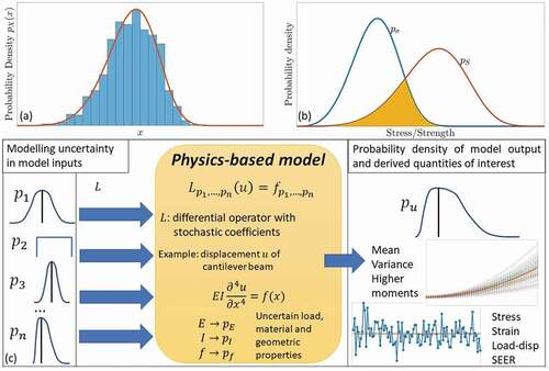
statistical modelling (primarily, data-driven)
structural reliability
stochastic structural mechanics (primarily, physics-based).
These categories should not be intended too rigidly, since hybrid combinations are also possible, as shown for example in, [Citation198] where a structural model with adhesive thickness modelled as a stochastic field was combined with a reliability model to compute the probability of failure for adhesively bonded composite patches.
In the statistical modelling approach, the failure state of adhesive joints is characterized by a stochastically varying physical quantity such as load, stress or time which is modelled as a random variable with a continuous probability density function
. The parameters of the probability density function are estimated from experimental data generated from tests where the adhesive joints are loaded until failure. In the attempt to account for the limited control and information over real materials, geometric dimensions and loads, the target of the quantitative analysis shifts from the deterministic conditions for failure to the probability that such an event occurs. For an arbitrarily small increment of the failure-driving variable
(e.g. load) applied to a large population of
nominally identical (e.g. in terms of manufacturing, age and loading conditions) joints, a certain number of failures will be observed. The resulting fractional change in the size of the population of functioning joints
can be identified (in the limit of arbitrarily large
) with the probability of failure for an individual joint randomly drawn from the population, that is
, which represents an informal definition for the notion of probability density function
. The probability of failure at a specific value of
is obtained by integration of the probability density function over the range of possible realizations of
up to
, which defines the cumulative distribution function of the random variable
, denoted as
. The most widely used statistical model in the literature on adhesive joints is the Weibull distribution, [Citation199–206] which is defined by the probability density function:
where is a nonnegative variable which characterizes the failure state of the joint, such as critical load, [Citation199,Citation205,Citation206] or a measure of stress in the adhesive at failure under tensile tests, shear tests[Citation200–203] or combinations thereof[Citation204];
denote the scale and shape parameters, respectively, and
a shift factor which is sometimes omitted (see to visualize the shape of Weibull PDF and CDF for different values of the parameters).
Figure 18. Weibull probability density (a) and cumulative distribution function (b) for different values of the scale and shape parameters .
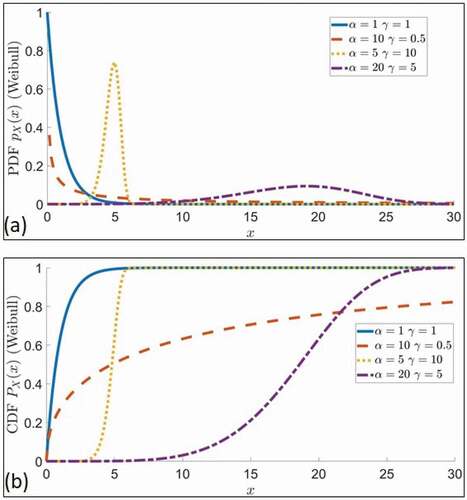
Weibull distribution finds broad application in the analysis of product reliability for a wide range of materials (e.g. metals, composites), failure mechanisms (e.g. fatigue, yielding, wear) and generally all the systems where the occurrence of failure localized at a small volume or component determines failure for the whole system (i.e. the weakest link theory). The reliability of a device such as a mechanical joint is defined as the probability that it performs without failure under stated operating conditions for a specified period of time .[Citation207] In general, the probability of safe performance (i.e. not failure), it is simply related to the probability of failure by , which in the case of Weibull distribution takes the form
All the parameters in Equationequations 15(15)
(15) and Equation16
(16)
(16) are estimated from experimental data by means of standard methods such as maximum likelihood, Q-Q plots, linear regression. Experimental methods reported in the literature to investigate the reliability of adhesively bonded joints include the tensile and shear tests, [Citation200] End-Notched Flexure test, [Citation206] and shear-tensile interaction test .[Citation204]
The sensitivity of the estimated probability of failure to geometric parameters such as adhesive thickness and overlap length has been investigated theoretically in[Citation199] and experimentally in[Citation205] (for a single lap aluminium joint with acrylic adhesive) and[Citation204] (for double lap joints of pultruded Glass Fibre Reinforced Polymer profiles). The onset of failure is related to the number of randomly distributed defects inside the adhesive, such as voids, inclusions, and kissing defects. As the volume of the adhesive increases, more defects are likely to be included in the adhesive and therefore the strength decreases, while the stress concentration near the ends of the adhesive layer decreases. The competition between the volume effect (which favours lesser thickness) and the concentration of stress at the ends (which favours greater thickness) results in the optimal thickness for which the strength of the adhesive is maximum. Assuming that the failure stress within elementary volumes of adhesive follows Weibull distribution, the scale effect can be theoretically derived for an arbitrary volume of adhesive .[Citation199]
Fitting probabilistic models to failure data of adhesive joints is a versatile approach to estimate the probability of failure for virtually any type of material combinations and bond geometry. However, these models provide little understanding about the conditions for the occurrence of failure. Modelling strategies which do not rely solely on empirical models have to be introduced to provide deeper insights into the physics of failure mechanisms and the effects of design parameters on the resistance of adhesive joints to failure.
As an alternative to direct estimation from experimental data, the framework of structural reliability[Citation207] offers the possibility to compute the failure probability of adhesive joints on the basis of their geometry, material properties and loads. The failure condition is characterized by the definition of a limit state function , where
denotes the set of design variables (e.g. material parameters, thickness, etc.), which might be all, or in part, specified as random variables with assigned probability density functions. A simple example of limit state function can be devised in terms of the stress state of the joint (expressed by some scalar measure
, to not overcomplicate the notation):
where the strength , is the maximum stress that the joint is capable to withstand without failure. EquationEquation 17
(17)
(17) exemplifies a general implication of limit state functions, that is the partitioning of the design space into regions of safe and unsafe performance, determined by the inequalities
and
, respectively. The stress state (or, equivalently, the external load) as well as the strength of the joint can be modelled as random variables with probability density functions estimated from failure data, as in .[Citation208] Alternatively, a model-based characterization of the stress state is also possible .[Citation198,Citation209–211] For example, the analytical model by Volkersen was considered in[Citation198] to quantify the shear stress inside the adhesive in composite-aluminium patches with randomly varying adhesive thickness. The maximum shear stress was then extracted from the numerical solution of the model and inserted in Equationequation 17
(17)
(17) as representative measure of the stress driving the occurrence of failure in the adhesive joint.
For a given failure mechanism, the associated limit state function is amenable of several parameterizations, which might include linear or nonlinear combinations of stochastic and deterministic variables. Independently of the specific form of the limit state function, the probability of failure in the framework of structural reliability is evaluated as
where is the joint probability density function of all the uncertain input variables and the integral is computed over the failure region of the design space. The multi-dimensional integral in Equationequation 18
(18)
(18) can be evaluated numerically via sampling techniques such as Monte Carlo simulations, [Citation207] or via semi-analytical methods such as FORM, which approximates the failure probability with
, where
is the standard normal distribution and the reliability index
is the solution of a constrained optimization problem in the design space .[Citation207]
Both statistical and reliability-based methods target the probability of failure as the main quantity of interest to characterize the structural performance of adhesive joints. Reliability and quality are closely related. Normally, quality focuses on the prevention of defects during the warranty phase, whereas reliability looks at preventing failures throughout the life cycle of the joint, that is from manufacturing to the end of service life. The derivation of safety margins for the design variables is crucial for the development of robust procedures for quality control and certification of load-carrying bonded structures. Safety margins quantify the range within which design variables may vary without failing to fulfil requirements such as “probability of failure less than 1%”. For example, the problem of random variations of adhesive thickness along the bondline was addressed in[Citation198] from a reliability perspective. In order to derive the safety margin which could bound the probability of failure for the joint below 1%, the adhesive thickness
was expressed as
where is local coordinate along the bondline and
the nominal design thickness. A parametric study was conducted by evaluating the right-hand-side of Equationequation 17
(17)
(17) for different safety margins, which enabled to determine the value of
corresponding to a maximum probability of failure of 1% (i.e.
). A practical indication that the authors of[Citation198] could draw from this analysis was that, in order to satisfy the safety requirement of
, the manufacturing process of the joint should be designed to make the adhesive thickness as close as possible to
rather than to the nominal value
.
As long as failure criteria can be expressed in terms of a limit state function which partitions the design space in safe and unsafe regions, the reliability of any type of adhesive joint can be quantified within the framework of structural reliability. The impact of the uncertain design variables on the probability of failure can be assessed through the evaluation of “importance factors”, which can often be done efficiently within the same computational framework used for , thus providing a quantitative criterion to reduce the number of random variables to be considered in the analysis. The probability of failure as computed through Equationequation 19
(19)
(19) incorporates the available information from experiments as well as theoretical models.
The role of experimental data differs between statistical (i.e. phenomenological) and structural (i.e. theoretical) models. While in statistical analysis the data drive the selection of the model to estimate the failure probability, structural models are derived from fundamental physical principles and data are used for calibration and validation purposes. Deterministic models acquire a stochastic character by introducing random variables to model parameters, loads or boundary conditions which are expected to be significantly affected by uncertainty due to intrinsic variability or lack of information. Mechanistic or physics-based modelling of adhesive joints under uncertainty is based on stochastic partial differential equations, which are discretized and solved numerically in space, time, and probability domains .[Citation212] For example, the following stochastic partial differential equation was derived in[Citation213] to assess the load-bearing capacity of adhesive anchors embedded in concrete under the effect of material degradation due to creep deformation, which makes the adhesive shear stiffness and strength uncertain:
where is the longitudinal displacement of the anchor (modelled as a rod with diameter
, Young modulus
and cross section area
),
the coordinate along the rod axis,
sample space, which is the set of all possible realizations of the random variables,
the adhesive thickness and
the position-dependent adhesive shear modulus. The specification of
and boundary conditions for Equationequation 20
(20)
(20) determine the displacement
and, therefore, the shear stress random field
, which is compared to the allowed maximum shear stress to identify regions of safe and unsafe performance in the design space.
Further applications of stochastic structural mechanics to adhesive joints include the study of crack propagation in a Double Cantilever Beam setup with random interface stiffness and elongation at break, [Citation214] and the sensitivity analysis of Finite Element Models of adhesively bonded metals with respect to uncertain cohesive zone parameters .[Citation215]
Probabilistic methods can be efficiently combined with analytical and numerical techniques to predict the occurrence of failure in adhesive joints, thus providing an assessment of the robustness of the conclusions drawn from the analysis, which is particularly relevant for the purpose of certification of novel structures. Reliability-based design offers a quantitative framework where the feasibility and safety of adhesive joints can be assessed at the very early phases of product development, opening wide opportunities for performance and cost optimization.
11. Additional considerations
Adhesive joints between dissimilar materials, made with adhesives curing at temperature have, at least, two identified sources of residual stresses associated with temperature. One source is associated to the chemical shrinkage during the curing stage, and the second source is associated with the different Thermal Expansion Coefficient (TEC) of the materials being joined. A comprehensive review of the different sources of stresses in adhesive joints is detailed in .[Citation216]
While some authors[Citation217] indicate that it is neither easy nor realistic to separate the stress changes due to the curing process from purely thermal effects, others[Citation218] argue instead that it is possible to clearly identify each of the two phenomena separately.
In the case of unidirectional long fibre reinforced materials, it is important to understand that for a general stacking sequence, residual stresses will appear inside the laminate, due to the different thermomechanical properties associated to the different orthotropic directions of the unidirectional reinforced material. Nevertheless, considering the laminate as an equivalent homogeneous orthotropic material, thermal effects will also appear if the equivalent TEC of the laminate is different than the TEC of the other material of the joint. Therefore, it is of paramount importance to calculate the equivalent TEC of the laminate from the thermomechanical properties of the individual plies of the laminate .[Citation219,Citation220] An excellent study of the influence of temperature on the strength reduction of adhesive joints with composite materials is the classical work by Hart-Smith, [Citation221] in which the main mechanisms contributing to the strength reduction of the joint are clearly identified and quantified: a) difference in the TEC of the materials, and b) values of the curing temperature of the adhesives.
Other important aspects when analysing temperature effects in adhesive joints are the thermal properties to take into account for the adhesive and the reference temperature value from which these thermal effects account from.
Characteristic temperatures polymeric materials such as adhesives are[Citation34] the glass transition temperature (Tg), which is particularly important for structural adhesives, the melting temperature (Tm), which has significance for partially crystalline polymers and negligible effect on noncrystalline or amorphous polymers (e.g. epoxides, phenolics, and acrylics), the decomposition temperature (Td) at which the adhesive undergoes chemical degradation, and the curing (Tc) and room temperatures (Tamb), which are typical reference values for the thermal effects in the cooling stage of the curing process, when residual thermal stresses are generated (see[Citation222] for further information).
A still debated question regards the temperature jump to take into account for the thermal residual stresses during the cooling stage of the curing process, that is whether to consider the glass transition temperature[Citation223] (ΔT = Tg-Tamb) or the curing temperature[Citation224] (ΔT = Tc-Tamb). The difference between Tg and Tc in some adhesives can be relatively large, [Citation222] which makes some authors[Citation225] argue that the reference temperature should be experimentally determined by means of a bi-material laminate which presents curvature after the curing stage; in that case, a gradual heating until the recovery of the flat original configuration would determine the more appropriate reference temperature.
Considering the adhesive as an isotropic material, the stress-strain law with temperature dependent properties is:
Where μ is the shear modulus, λ is the Lame constant and is the TEC.
An accurate evaluation of the stresses developed during the cooling stage of the curing process should take into account the detailed temperature dependency of the TEC (T), but if only the final situation (at T) is of interest, Equationequation (21)
(21)
(21) can be reduced to the simpler relation:
Where αavg is the average value of the TEC in the temperature range (ΔT = T-T0).The approximation that leads to Equationequation (22)(22)
(22) from Equationequation (21)
(21)
(21) tends to overestimate the residual stress values, as pointed out by[Citation226] and also observed experimentally in .[Citation227]
In[Citation227] two simple experiments were conducted to check the potential residual stress field developed in the cooling stage of the curing process. A composite-metal single-lap joint was bonded using an adhesive curing at Tc = 115°C. The thermal stresses in the critical part of the joint (where failure starts) are numerically calculated by means of FEA for different ΔT. The stress fields are completely different when considering the expected ΔT = Tc-Tamb = 115–25 = 90°C than those obtained when considering lower ΔT values. This lower ΔT are completely equivalent to testing the joint at temperatures above the room temperature, and those test were carried out in[Citation227] finding absolutely no significant influence in the failure load or failure path (considering detailed failure path observations at the critical part of the joint). These experimental findings indicate that the expected residual stress profile has not fully developed, maybe due to the relaxation effects mentioned in[Citation225] in presence of high stress gradients and to the viscoelastic behaviour of the adhesive.
Another experiment carried out in[Citation227] investigated time-dependent relaxation effects in 24 samples of the same single-lap joint configuration which were bonded and tested at equal intervals of time (in a logarithmic scale) from just 15 minutes after the curing stage (the necessary time to prepare the sample) to a 7 months later. The two bonded materials had different TEC and the adhesive was cured at temperature, letting the expected residual stress state to develop. The test results did not show any significant variation, see[Citation227,Citation228] for further details and information. No relaxation was observed after 15 minutes from the end of the curing process. If any relaxation effect takes place in the adhesive layer, it might occur during the cooling stage of the curing process.
In summary, it seems that thermal residual stresses that could appear in the cooling stage of the curing when using an adhesive curing at temperature are overestimated if no relaxation effects are taken into account.
Different techniques have been used in bonded joints to measure (direct or indirectly) thermal stress fields. Photoelasticity[Citation229] was successfully used in bonded structures, as well as Moire interferometry[Citation230,Citation231] giving full displacement fields, and strain gauges, [Citation232,Citation233] which provide only local information. Indirect measurements, using nonsymmetric laminates[Citation216,Citation224] were also used to determine stress free reference temperature in bonded joints, or embedded optical fiber Bragg grating sensors[Citation232] for measurements inside the adhesive layer. More sophisticated methods such as Neutron diffraction[Citation234] and X-ray diffraction[Citation235] also allows internal and surface (or near surface) strain measurement, respectively. Also, Digital Image Correlation has been used to experimentally measure the residual strain/stress fields .[Citation236]
Theory and experiments show that adhesive joints between dissimilar materials generate residual thermal stresses, which increase with the thermal expansion coefficient mismatch and with the curing temperature value. Although it is important to take into account these thermal stresses for failure initiation prediction, the complexity of different relaxation mechanisms in the adhesive complicate the exact determination of the residual thermal stresses, especially in the long-term.
12. Concluding remarks
In the present paper, a review of some of the most widely used failure theories and models for adhesive joints has been performed. The evaluation has been performed by experts from different scientific areas, so it represents a more generalized viewpoint. summarizes the evaluation findings for the different methods that have been reviewed. Thus, it may be used as a guide for a quick selection of the method.
Table 2. Evaluation summary of the different failure theories and models.
Nomenclature
τxy:adhesive shear stress (SLS specimen)
F:Axial tensile force (SLS specimen)
b:Adherent’s width (SLS specimen)
L:Adherent’s length (SLS specimen)
σeq:Equivalent stress
σeff:Effective stress
LPM:Critical distance
σeff,PM:Effective stress at the critical distance
FAPP:Operational force
FREF:Reference forcé
a:Half crack length
E:Young’s modulus
GIC:Mode I critical energy reléase rate
σc:Critical remote stress
Πp:Total potential energy
:Crack area
KiStress intensity factor for mode i
Gi:Energy release rate
GI:Mode I energy release rate
GII:Mode II energy release rate
GIII:Mode III energy release rate
F11, F22, F33: Corresponding reaction forces on the crack tip
Δx, Δy, Δz: Relative displacements at the crack tip
Kn (n = 1, …, N):Generalized Stress Intensity Factors (GSIFs)
fij():Characteristic angular function for stresses
λn:Stress singularities
Wp:Elastic potential energy
σR:Normal interface strength
τR:Shear interface strength
Ψ:Mode mixity
X:Random variable
px:Probability density function
N:Population
α, γ>0:Scale and shape parameters
x0:Shift factor
Pnf(x):Probability of failure
:Weibull distribution
g(x):Limit state function
fX:Joint probability density function
Cs:Safety margin
:Local coordinate along the bondline
w(z,ω):Longitudinal displacement
G:Adhesive shear modulus
K:Generalized Stress Intensity Factor (GSIFs)
λn:Order of stress singularity
fij():Characteristic angular function for stresses
L0:Characteristic length
Tg:Glass transition temperature
Tm:Melting temperature
Td:Decomposition temperature
Tc:Curing temperature
Tamb:Room temperature
:Thermal expansion coefficient (TEC)
avg:Average value of the thermal expansion coefficient
:Shear modulus
λ:Lamé constant
Acknowledgements
This publication is the outcome of a collaborative work that has been performed in the frame of the COST Action CA18120 (CERTBOND - https://certbond.eu/), supported by COST (European Cooperation in Science and Technology - https://www.cost.eu/).
Correction Statement
This article has been republished with minor changes. These changes do not impact the academic content of the article.
Additional information
Funding
References
- Pantelakis, S.; Tserpes, K., eds. Revolutionizing Aircraft Materials and Processes; Springer: Cham, 2020.
- Tserpes, K.;. Adhesive Bonding of Aircraft Structures. In Revolutionizing Aircraft Materials and Processes; Pantelakis, S., Tserpes, K., Eds.; Springer: Cham, 2020, 337–357.
- Pantelakis, S.; Tserpes, K. I. Adhesive Bonding of Composite Aircraft Structures: Challenges and Recent Developments. Sci. China Phys. Mech. Astr. 2014, 57(1), 2–11. DOI: 10.1007/s11433-013-5274-3.
- EASA. Acceptable Means of Compliance; AMC, 2010, 20–29.
- CertBond-COST Action CA-18120. https://certbond.eu
- Da Silva, L. F. M.;, Ed. Modeling of Adhesively Bonded Joints; Springer-Verlag Berlin Heidelberg., 2008.
- Da Silva, L. F. M.; Das Neves, P. J. C.; Adams, R. D.; Spelt, J. K. Analytical Models of Adhesively Bonded Joints- Part I: Literature Survey. Int. J. Adhes. Adhes. 2009, 29(3), 319–330. DOI: 10.1016/j.ijadhadh.2008.06.005.
- Da Silva, L. F. M.; Das Neves, P. J. C.; Adams, R. D.; Spelt, J. K. Analytical Models of Adhesively Bonded Joints- Part II: Comparative Study. Int. J. Adhes. Adhes. 2009, 29(3), 331–341. DOI: 10.1016/j.ijadhadh.2008.06.007.
- Ramalho, L. D. C.; Campilho, R. D. S. G.; Belinha, J.; Da Silva, L. F. M. Static Strength Prediction of Adhesive Joints: A Review. Int. J. Adhes. Adhes. 2020, 96, 102451. DOI: 10.1016/j.ijadhadh.2019.102451.
- Dragoni, E.; Goglio, L.; Kleiner:, F. Designing Bonded Joints by Means of the JointCalc Software. Int. J. Adh Adhes. 2010, 30(5), 267–280. DOI: 10.1016/j.ijadhadh.2009.11.002.
- Da Silva, L. F. M.; Lima, R. F. T.; Teixera, R. M. S. Development of a Computer Program for the Design of Adhesive Joints. J. Adhes. 2009, 85(12), 889–918. DOI: 10.1080/00218460903307761.
- Rodríguez, R. Q.; De Paiva, W. P.; Sollero, P.; Bertoni Rodrigues, M. R.; De Albuquerque, É. L. Failure Criteria for Adhesively Bonded Joints. Int. J. Adhes. Adhes. 2012, 37, 26–36. DOI: 10.1016/j.ijadhadh.2012.01.009.
- Adams, R. D.; Peppiatt, N. A. Effect of Poisson’s Ratio Strains in Adherends on Stresses of an Idealized Lap Joint. J. Strain Anal. Eng. Des. 1973, 8(2), 134–139. DOI: 10.1243/03093247V082134.
- Oterkus, E.; Barut, A.; Madenci, E.; Smeltzer, S. S.; Ambur, D. R. Nonlinear Analysis of Bonded Composite Single-lap Joints. Collect Tech Pap- 45th AIAA/ASME/ASCE/AHS/ASC Struct., Struct. Dyn. and Mater. Conf.; 12th AIAA/ASME/AHS Adapt. Struct. Conf.; 6th AIAA Non-Deterministic Approaches Forum; 5th AIAA Gossamer Spacecraft Forum, Palm Springs, CA. 2004, 72, 1–555, DOI: 10.2514/6.2004-1560.
- Volkersen, O.;. Die Niektraftverteiling in Zugbeanspruchten mit Konstanten Laschenquerschritten. Luftfahrtforschung. 1938, 7, 15–41.
- Goland, M.; Reer, E. The Stresses in Cemented Joints. J. Appl. Mech. 1944, 66(1), A17. DOI: 10.1115/1.4009336.
- Wah, T.;. Stress Distribution in a Bonded Anisotropic Lap Joint. J Eng Mater Technol Trans. 1973, 95(3), 174–181. DOI: 10.1115/1.3443146
- Hart-Smith, L. J.;. NASA Contract Report, NASA CR-112236, 1973.
- Pirvics, J.;. Two Dimensional Displacement-stress Distributions in Adhesive Bonded Composite Structures. J. Adhes. 1974, 6(3), 207–228. DOI: 10.1080/00218467408075027.
- Grimes, G.; Greimann, L. Analysis of Discontinuities, Edge Effects, and Joints (In Composite Structures). Compos. Mater. 1975, 8, 135–230.
- Renton, J. W.; Vinson, J. R. The Efficient Design of Adhesive Bonded Joints. J. Adhes. 1975, 7(3), 175–193. DOI: 10.1080/00218467508075049.
- Renton, J. W.; Vinson, J. R. On the Behavior of Bonded Joints in Composite Material Structures. Eng. Fract. Mech. 1975, 7(1), 175–193. DOI: 10.1080/00218467508075049.
- Srinivas, S.; NASA Technical Note 1975, NASA TN D-7855.
- Allman, D. J.;. A Theory for Elastic Stresses in Adhesive Bonded Lap Joints. Q. J. Mech. Appl. Math. 1977, 30(4), 415–436. DOI: 10.1093/qjmam/30.4.415.
- Ojalvo, I. U.; Eidinoff, H. L. Bond Thickness Effects upon Stresses in Single-lap Adhesive Joints. AIAA J. 1978, 16(3), 204–211. DOI: 10.2514/3.60878.
- Delale, F.; Erdogan, F.; Aydinoglu, M. N. Stresses in Adhesively Bonded Joints: A Closed-Form Solution. J. Compos. Mater. 1981, 15(3), 249–271. DOI: 10.1177/002199838101500305.
- Bigwood, D. A.; Crocombe, A. D. Elastic Analysis and Engineering Design Formulae for Bonded Joints. Int. J. Adhes. Adhes. 1989, 9(4), 229–242. DOI: 10.1016/0143-7496(89)90066-3.
- Bigwood, D. A.; Crocombe, A. D. Non-linear Adhesive Bonded Joint Design Analyses. Int. J. Adhes. Adhes. 1990, 1, 31–41. DOI: 10.1016/0143-7496(90)90010-u.
- Cheng, S.; Chen, D.; Shi, Y. Analysis of Adhesive‐Bonded Joints with Nonidentical Adherends. ASCE J Eng Mech. 1991, 117(3), 605–623. DOI: 10.1061/(ASCE)0733-9399(1991)117:3(605).
- Crocombe, A. D.; Bigwood, D. A. Development of a Full Elasto-plastic Adhesive Joint Design Analysis. J. Strain Anal. Eng. Des. 1992, 27(4), 211–218. DOI: 10.1243/03093247V274211.
- Adams, R. D.; Mallick, V. A Method for the Stress Analysis of Lap Joints. J. Adhes. 1992, 38(3–4), 199–217. DOI: 10.1080/00218469208030455.
- Tong, L.;. Bond Strength for Adhesive-bonded Single-lap Joints. Acta Mech. 1996, 117(1–4), 101–113. DOI: 10.1007/BF01181040.
- Yang, C.; Pang, S. S. Stress-strain Analysis of Single-lap Composite Joints under Tension. J Eng Mater Technol Trans ASME. 1996, 118(2), 247–255. DOI: 10.1115/1.2804896.
- Frostig, Y.; Thomsen, O. T.; Mortensen, F. Analysis of Adhesive-Bonded Joints, Square-End, and Spew-Fillet—High-Order Theory Approach. J. Eng. Mech. 1999, 125(11), 1298–1307. DOI: 10.1061/(asce)0733-9399(1999)125:11(1298).
- Sawa, T.; Liu, J.; Nakano, K.; Tanaka, J. Two-dimensional Stress Analysis of Single-lap Adhesive Joints of Dissimilar Adherends Subjected to Tensile Loads. J. Adhes. Sci. Technol. 2000, 14(1), 43–66. DOI: 10.1163/156856100742104.
- Mortensen, F.; Thomsen, O. T. Analysis of Adhesive Bonded Joints: A Unified Approach. Compos. Sci. Technol. 2002, 62, 1011–1031. DOI: 10.1016/S0266-3538(02)00030-1.
- Adams, R. D.; Comyn, J.; Wake, W. C. Structural Adhesive Joints in Engineering, 2nd ed.; Chapman & Hall: London, 1997.
- Wang, R. X.; Cui, J.; Sinclair, A. N.; Spelt, J. K. Strength of Adhesive Joints with Adherend Yielding: I. Analytical Model. J. Adhes. 2003, 79(1), 23–48. DOI: 10.1080/00218460309561.
- Smeltzer, S. S.; Klang, E. C. In: Proceedings of the 18th annual technical conference. Gainesville, FL, USA: American Society for Composites 2003,104.
- Oplinger, D. W.;. Effects of Adherend Deflections in Single Lap Joints. Int. J. Solids Struct. 1994, 31(18), 2565–2587. DOI: 10.1016/0020-7683(94)90037-X.
- Zhao, X.; Stress and failure analysis of adhesively bonded lap joints, PhD dissertation, University of Bristol, 1991.
- Zou, G. P.; Shahin, K.; Taheri, F. An Analytical Solution for the Analysis of Symmetric Composite Adhesively Bonded Joints. Compos. Struct. 2004, 65(3–4), 499–510. DOI: 10.1016/j.compstruct.2004.01.007.
- Lee, J.; Kim, H. Stress Analysis of Generally Asymmetric Single Lap Adhesively Bonded Joints. J. Adhes. 2005, 81(5), 443–472. DOI: 10.1080/00218460590944918.
- Adams, R. D.; Peppiatt, N. A. Stress Analysis of Adhesive-bonded Lap Joints. J. Strain Anal. Eng. Des. 1974, 9(3), 185–196. DOI: 10.1243/03093247V093185.
- Gleich, D. M.; Van Tooren, M. J. L.; Beukers, A. Analysis and Evaluation of Bondline Thickness Effects on Failure Load in Adhesively Bonded Structures. J. Adhes. Sci. Technol. 2001, 15(9), 1091–1101. DOI: 10.1163/156856101317035503.
- Da Silva, L. F. M.; Rodrigues, T. N. S. S.; Figueiredo, M. A. V.; de Moura, M. F. S. F.; Chousal, J. A. G. Effect of Adhesive Type and Thickness on the Lap Shear Strength. J. Adhes. 2006, 82(11), 1091–1115. DOI: 10.1080/00218460600948511.
- Pasha, R. A.; Hammouda, M. M. I. A Model for Notch Fatigue Life. Mater. Sci. Eng. A. 2008, 483–484. DOI: 10.1016/j.msea.2006.10.187.
- Sakane, M.; Zhang, S.; Kim, T. Notch Effect on Multiaxial Low Cycle Fatigue. Int. J. Fatigue. 2011, 33(8), 959–968. DOI: 10.1016/j.ijfatigue.2011.01.011.
- Susmel, L.; Taylor, D. Fatigue Design in the Presence of Stress Concentrations. J. Strain Anal. Eng. Des. 2003, 38(5), 443–452. DOI: 10.1243/03093240360713496.
- Pluvinage, G.;. Fatigue and Fracture Emanating from Notch; the Use of the Notch Stress Intensity Factor. Nucl. Eng. Des. 1998, 185(2–3), 173–184. DOI: 10.1016/S0029-5493(98)00183-6.
- Taylor, D.;. The Theory of Critical Distances. Eng. Fract. Mech. 2008, 75(7), 1696–1705. DOI: 10.1016/j.engfracmech.2007.04.007.
- Spaggiari, A.; Castagnetti, D.; Dragoni, E.; Bulleri, S. The Use of the Theory of Critical Distance and the Stress-gradient Approach in the Fatigue Life Estimation of Notched Components. Proc. Inst. Mech. Eng. L J. Mater. Des. Appl. 2016, 230, 735–747. DOI: 10.1177/1464420715605137.
- Castagnetti, D.; Dragoni, E. Standard Finite Element Techniques for Efficient Stress Analysis of Adhesive Joints. Int. J. Adhes. Adhes. 2009, 29(2), 125–135. DOI: 10.1016/j.ijadhadh.2008.01.005.
- Neuber, H.; Theory of Notch Stresses: Principles for Exact Calculation of Strength with Reference to Structural Form and Material, 1958.
- Peterson, R. E.;. Notch Sensitivity. Metal Fatigue. 1959, 293–306.
- Taylor, D.;. Geometrical Effects in Fatigue: A Unifying Theoretical Model. Int. J. Fatigue. 1999, 21(5), 413–420. DOI: 10.1016/S0142-1123(99)00007-9.
- Hoey, D.; Taylor, D. Fatigue in Porous PMMA: The Effect of Stress Concentrations. Int. J. Fatigue. 2008, 30, 989–995. DOI: 10.1016/j.ijfatigue.2007.08.022.
- Beber, V. C.; Schneider, B.; Brede, M. Efficient Critical Distance Approach to Predict the Fatigue Lifetime of Structural Adhesive Joints. Eng. Fract. Mech. 2019, 214, 365–377. DOI: 10.1016/j.engfracmech.2019.03.022.
- Susmel, L.;. The Theory of Critical Distances: Applications in Fatigue. In Fracture of Nano and Engineering Materials and Structures; Gdoutos, E. E., Ed.; Springer: Dordrecht Netherlands, 2006, 1101–1102.
- Zhao, X.; Adams, R. D.; Da Silva, L. F. M. Single Lap Joints with Rounded Adherend Corners: Experimental Results and Strength Prediction. J. Adhes. Sci. Technol. 2011, 28(8), 837. DOI: 10.1163/016942410X520880.
- Clark, J. D.; McGregor, I. J. Ultimate Tensile Stress over A Zone: A New Failure Criterion for Adhesive Joints. J. Adhes. 1993, 42(4), 227–245. DOI: 10.1080/00218469308026578.
- Towse, A.; Davies, R.; Clarke, A.; Wisnom, M.; Adams, R. D.; Potter, K. The Design and Analysis of High Load Intensity Adhesively Bonded Double Lap Joints. In Proceedings of the Fourth International Conference on Deformation and Fracture of Composites; Manchester,1997.
- Crocombe, A. D.;. Global Yielding as a Failure Criterion for Bonded Joints. Int. J. Adhes. Adhes. 1989, 9(3), 145–153. DOI: 10.1016/0143-7496(89)90110-3.
- Khoramishad, H.; Akhavan-Safar, A.; Ayatollahi, M.; Da Silva, L. F. M. Predicting Static Strength in Adhesively Bonded Single Lap Joints Using a Critical Distance Based Method: Substrate Thickness and Overlap Length Effects. Proc. Inst. Mech. Eng. L J. Mater. Des. Appl. 2016, 231, 237–246. DOI: 10.1177/1464420716666427.
- Akhavan-Safar, A.; Ayatollahi, M. R.; Da Silva, L. F. M. Strength Prediction of Adhesively Bonded Single Lap Joints with Different Bondline Thicknesses: A Critical Longitudinal Strain Approach. Int. J. Solids Struct. 2017, 109, 189–198. DOI: 10.1016/j.ijsolstr.2017.01.022.
- Cruz-G, C. E.; Akhavan-Safar, A.; Da Silva, L. F. M.; Ayatollahi, M. R. On the Evaluation of a Critical Distance Approach for Failure Load Prediction of Adhesively Bonded Dissimilar Materials. Contin Mech Thermodyn. 2020, 32(6), 1647–1657. DOI: 10.1007/s00161-020-00871-7.
- Schneider, B.; Beber, V. C.; Brede, M. Estimation of the Lifetime of Bonded Joints under Cyclic Loads at Different Temperatures. J. Adhes. 2016, 92(7–9), 795–817. DOI: 10.1080/00218464.2015.1114928.
- Beber, V. C.; Fernandes, P. H. E.; Fragato, J. E.; Schneider, B.; Brede, M. Influence of Plasticity on the Fatigue Lifetime Prediction of Adhesively Bonded Joints Using the Stress-life Approach. Appl. Adhes. Sci. 2016, 4(1), 26. DOI: 10.1186/s40563-016-0062-8.
- Beber, V. C.; Fernandes, P. H. E.; Schneider, B.; Brede, M.; Mayer, B. Fatigue Lifetime Prediction of Adhesively Bonded Joints: An Investigation of the Influence of Material Model and Multiaxiality. Int. J. Adhes. Adhes. 2017, 78, 240–247. DOI: 10.1016/j.ijadhadh.2017.08.007.
- Schmidt, H.; Baumgartner, J.; Melz, T. Fatigue Assessment of Joints Using the Local Stress Field. Mat.-wiss. U. Werkstofftech. 2015, 46(2), 145–155. DOI: 10.1002/mawe.201400369.
- Castro Sousa., F.; Akhavan-Safar, A.; Goyal, R.; Da Silva, V. L. F. M. Fatigue Life Estimation of Single Lap Adhesive Joints Using a Critical Distance Criterion: An Equivalent Notch Approach. Mech. Mater. 2021, 153, 103–670. DOI: 10.1016/j.mechmat.2020.103670.
- Griffith, A. A.;. The Phenomena of Rupture and Flow in Solids, Griffith.pdf. Philos. Trans. R Soc. London. 1921, 221, 582–593.
- Irwin, G. R.;. Analysis of Stresses and Strains near the End of a Crack Traversing a Plate. Trans. ASME, J. Appl. Mech. 1957, 24(3), 361–364. DOI: 10.1115/1.4011547.
- Rice, J. R.;. A Path Independent Integral and the Approximate Analysis of Strain Concentration by Notches and Cracks. J. Appl. Mech. 1968, 35(2), 379–386. DOI: 10.1115/1.3601206.
- Williams, M. L.;. The Stresses around a Fault or a Crack in Dissimilar Media. Bull Seismol Soc Am. 1959, 49(2), 199–204. DOI: 10.1785/BSSA0490020199.
- Rice, J. R.;. Elastic Fracture Concepts for Interfacial Cracks. J. Appl. Mech. 1988, 55(1), 98–103. DOI: 10.1115/1.3173668.
- Comninou, M.;. The Interface Crack. J Appl Mech Trans ASME. 1977, 44(4), 631–666. DOI: 10.1115/1.3424148.
- Wang, C. H.;. Fracture of Interface Cracks under Combined Loading. Eng. Fract. Mech. 1997, 56, 77–86. DOI: 10.1016/s0013-7944(96)00111-7.
- Ducept, F.; Davies, P.; Gamby, D. Mixed Mode Failure Criteria for a Glass/epoxy Composite and an Adhesively Bonded Composite/composite Joint. Int. J. Adhes. Adhes. 2000, 20(3), 233–244. DOI: 10.1016/S0143-7496(99)00048-2.
- Carraro, P. A.; Meneghetti, G.; Quaresimin, M.; Ricotta, M. Crack Propagation Analysis in Composite Bonded Joints under Mixed-mode (I+II) Static and Fatigue Loading: Experimental Investigation and Phenomenological Modelling. J. Adhes. Sci. Technol. 2013, 27(11), 1179–1196. DOI: 10.1080/01694243.2012.735902.
- Adamos, L.; Tsokanas, P.; Loutas, T. An Experimental Study of the Interfacial Fracture Behavior of Titanium/CFRP Adhesive Joints under Mode I and Mode II Fatigue. Int. J. Fatigue. 2020, 136, 105586. DOI: 10.1016/j.ijfatigue.2020.105586.
- Hutchinson, J. W.; Suo, Z. Mixed Mode Cracking in Layered Materials. Adv. Appl. Mech. 1991, 29, 63–191. DOI: 10.1016/S0065-2156(08)70164-9.
- Kinloch, A. J.; Osiyemi, S. O. Predicting the Fatigue Life of Adhesively-Bonded Joints. J. Adhes. 1993, 43(1–2), 73–90. DOI: 10.1080/00218469308026589.
- Abdel Wahab, M. M.; Ashcroft, I. A.; Crocombe, A. D.; Smith, P. A. Numerical Prediction of Fatigue Crack Propagation Lifetime in Adhesively Bonded Structures. Int. J. Fatigue. 2002, 24(6), 705–709. DOI: 10.1016/S0142-1123(01)00173-6.
- Rocha, A. V. M.; Akhavan-Safar, A.; Carbas, R.; Marques, E. A. S.; Goyal, R.; El-Zein, M.; Da Silva, L. F. M. Paris Law Relations for an Epoxy-based Adhesive. Proceedings of the Institution of Mechanical Engineers Part L. J Mater Des Appl. 2020, 234(2), 291-299. DOI: 10.1177/1464420719886469.
- Cheuk, P. T.; Tong, L.; Wang, C. H.; Baker, A.; Chalkley, P. Fatigue Crack Growth in Adhesively Bonded Composite-metal Double-lap Joints. Compos. Struct. 2002, 57(1–4), 109–115. DOI: 10.1016/S0263-8223(02)00074-0.
- Quaresimin, M.; Ricotta, M. Life Prediction of Bonded Joints in Composite Materials. Int. J. Fatigue. 2006, 28(10), 1166–1176. DOI: 10.1016/j.ijfatigue.2006.02.005.
- Carraro, P. A.; Meneghetti, G.; Quaresimin, M.; Ricotta, M. Crack Propagation Analysis in Composite Bonded Joints under Mixed-mode (I+II) Static and Fatigue Loading: A Damage-based Model. J. Adhes. Sci. Technol. 2013, 7(13), 1393–1406. DOI: 10.1080/01694243.2012.735901.
- Ji, G.; Ouyang, Z.; Li, G. Effects of Bondline Thickness on Mode-II Interfacial Laws of Bonded Laminated Composite Plate. Int. J. Fract. 2011, 168(2), 197–207. DOI: 10.1007/s10704-010-9571-9.
- Ji, G.; Ouyang, Z.; Li, G.; Ibekwe, S.; Pang, S. S. Effects of Adhesive Thickness on Global and Local mode-I Interfacial Fracture of Bonded Joints. Int. J. Solids Struct. 2010, 47(18–19), 2445. DOI: 10.1016/j.ijsolstr.2010.05.006.
- Sarrado, C.; Turon, A.; Costa, J.; Renart, J. On the Validity of Linear Elastic Fracture Mechanics Methods to Measure the Fracture Toughness of Adhesive Joints. Int. J. Solids Struct. 2016, 81, 110–116. DOI: 10.1016/j.ijsolstr.2015.11.016.
- Rabinovitch, O.;. Debonding Analysis of Fiber-reinforced-polymer Strengthened Beams: Cohesive Zone Modeling versus a Linear Elastic Fracture Mechanics Approach. Eng. Fract. Mech. 2008, 75(10), 2842–2859. DOI: 10.1016/j.engfracmech.2008.01.003.
- Sun, F.; Blackman, B. R. K. A DIC Method to Determine the Mode I Energy Release Rate G, the J-integral and the Traction-separation Law Simultaneously for Adhesive Joints. Eng. Fract. Mech. 2020, 234, 107097. DOI: 10.1016/j.engfracmech.2020.107097.
- Rybicki, E. F.; Kanninen, M. F. A Finite Element Calculation of Stress Intensity Factors by A Modified Crack Closure Integral. Eng. Fract. Mech. 1977, 9(4), 931–938. DOI: 10.1016/0013-7944(77)90013-3.
- Krueger, R.;. 2015. The Virtual Crack Closure Technique for Modelling Interlaminar Failure and Delamination in Advanced Composite Materials. In Woodhead Publishing Series in Composites Science and Engineering, Numerical Modelling of Failure in Advanced Composite Materials, Camanho, P. P., Hallett, S. R., Eds., 3–53. Woodhead Publishing, Cambringe, England: DOI:10.1016/B978-0-08-100332-9.00001-3.
- Jokinen, J.; Wallin, M.; Saarela, O. Applicability of VCCT in Mode I Loading of Yielding Adhesively Bonded Joints—a Case Study. Int. J. Adhes. Adhes. 2015, 62, 85–91. DOI: 10.1016/j.ijadhadh.2015.07.004.
- Senthil, K.; Arockiarajan, A.; Palaninathan, R. Numerical Study on the Onset of Initiation of Debond Growth in Adhesively Bonded Composite Joints. Int. J. Adhes. Adhes. 2018, 84, 202–219. DOI: 10.1016/j.ijadhadh.2018.03.009.
- Quaresimin, M.; Ricotta, M. Stress Intensity Factors and Strain Energy Release Rates in Single Lap Bonded Joints in Composite Materials. Comp. Sci. Technol. 2006, 66(5), 647–656. DOI: 10.1016/j.compscitech.2005.07.036.
- Pirondi, A.; Giuliese, G.; Moroni, F.; Bernasconi, A.; Jamil, A. Comparative Study of Cohesive Zone and Virtual Crack Closure Techniques for Three Dimensional Fatigue Debonding. J. Adhes. 2014, 90(5–6), 457–481. DOI: 10.1080/00218464.2013.859616.
- Jokinen, J.; Kanerva, M.; Wallin, M.; Saarela, O. The Simulation of a Double Cantilever Beam Test Using the Virtual Crack Closure Technique with the Cohesive Zone Modelling. Int. J. Adhes. Adhes. 2019, 88, 50–58. DOI: 10.1016/j.ijadhadh.2018.10.015.
- De Carvalho, N. V.; Mabson, G. E.; Krueger, R.; Deobal, L. R. A New Approach to Model Delamination Growth in Fatigue Using the Virtual Crack Closure Technique without Re-meshing. Eng. Fract. Mech. 2019, 222, 106614. DOI: 10.1016/j.engfracmech.2019.106614.
- Floros, I. S.; Tserpes, K. I.; (2016). A Comparison between CZM and VCCT Methods in Predicting Mixed-mode Crack Growth in Composite Bonded Joints with and without Crack Stoppers. In Proceedings of the 6th EASN International Conference on Innovation in European Aeronautics Research, 18-21 October 2016 Porto, Portugal.
- Wieghardt, K.;. Über Das Spalten und Zerreissen Elastischer Körper. Z. Math. Phys. 1907, 55, 60–103.
- Stress Singularities, W. M.;. Resulting from Various Boundary Conditions in Angular Corners of Plates in Extension. J. Appl. Mech. 1952, 19(4), 526–528. DOI: 10.1115/1.4010553.
- Malyshev, B. M.; Salganik, R. L. The Strength of Adhesive Joints Using the Theory of Cracks. Int J Fract Mech. 1965, 1, 114–128. DOI: 10.1007/BF00186749.
- Bogy, D. B.; Wang, K. C. Stress Singularities at Interface Corners in Bonded Dissimilar Isotropic Elastic Materials. Int. J. Solids Struct. 1971, 7(8), 993–1005. DOI: 10.1016/0020-7683(71)90077-1.
- Hein, V. L.; Erdogan, F. Stress Singularities in a Two-material Wedge. Int J Fract Mech. 1971, 7(3), 317–330. DOI: 10.1007/BF00184307.
- Dempsey, J. P.; Sinclair, G. B. On the Stress Singularities in the Plane Elasticity of the Composite Wedge. J. Elast. 1979, 4(4), 373–391. DOI: 10.1007/BF00044615.
- Nicaise, S.; Sändig, A.-M. General Interface Problems I/II. Math. Method Appl. Sci. 1994, 17(6), 395–450. DOI: 10.1002/mma.1670170602.
- Sinclair, G. B.;. Logarithmic Stress Singularities Resulting from Various Boundary Conditions in Angular Corners of Plates in Extension. J Appl Mech Trans ASME. 1999, 66(2), 556–559. DOI: 10.1115/1.2791085.
- Gradin, P. A.; Groth, H. L. A Fracture Criterion for Adhesive Joints in Terms of Material Induced Singularities. Proceedings of the Third International Conference on Numerical Methods in Fracture Mechanics,1984. Pineridge Press, Universtity College, Swansea.
- Hattori, T.; Sakata, S.; Hatsuda, T.; Murakami, G. A Stress Singularity Parameters Approach for Evaluating Adhesive Strength. Trans Jpn Soc Mech Eng Ser A. 1988, 31, 718–723. DOI: 10.1299/kikaia.54.597.
- Ting, T. C. T.;. Stress Singularities at the Tip of Interfaces in Polycrystals. In Damage and Failure of Interfaces; Rossmanith, H.-P., Ed.; Balkema, Rotterdam, 1997, 75–82.
- Mantič, V.; Barroso, A.; París, F. Singular Elastic Solutions in Anisotropic Multimaterial Corners. Applications to Composites. In Mathematical Methods and Models in Composites; Imperial College Press, London, UK. 2014, 425–495.
- Lefebvre, D. R.; Dillard, D. A.; Dillard, J. G. A Stress Singularity Approach for the Prediction of Fatigue Crack Initiation in Adhesive Bonds. Part 2: Experimental. The Journal of Adhesion. 1999, 70(1–2), 139–154. DOI: 10.1080/00218469908010491.
- Imanaka, M.; Ishii, K.; Nakayama, H. Evaluation of Fatigue Strength of Adhesively Bonded Single and Single Step Double Lap Joints Based on Stress Singularity Parameters. Eng. Fract. Mech. 1999, 62(4–5), 409–424. DOI: 10.1016/s0013-7944(98)00111-8.
- Meneghetti, G.; Quaresimin, M.; Ricotta, M. Influence of the Interface Ply Orientation on the Fatigue Behaviour of Bonded Joints in Composite Materials. Int. J. Fatigue. 2010, 32(1), 82–93. DOI: 10.1016/j.ijfatigue.2009.02.008.
- Hwu, C.; Kuo, T. L. A Unified Definition for Stress Intensity Factors of Interface Corners and Cracks. Int. J. Solids Struct. 2007, 44(18–19), 6340–6359. DOI: 10.1016/j.ijsolstr.2007.02.031.
- Ren, F.; Noda, N. A.; Costa, A. R.; Correr-Sobrinho, L.; Pfeifer, C. S. Adhesive Strength Evaluation for Three-dimensional Butt Joint in Terms of the Intensity of Singular Stress Field on the Interface Outer Edge. Int. J. Adhes. Adhes. 2020, 103, 98102549. DOI: 10.1016/j.ijadhadh.2020.102549.
- Zappalorto, M.; Carraro, P.; Quaresimin, M. Analytical Solution For The Three-Dimensional Stress Fields In Anisotropic Composite Bimaterial Corners. Compos. Struct. 2015, 122, 127–138. DOI: 10.1016/j.compstruct.2014.11.045.
- Breto, R.; Chiminelli, A.; Lizaranzu, M.; Study, R. R. Of The Singular Term In Mixed Adhesive Joints. Int. J. Adhes. Adhes. 2017, 76, 11–16. DOI: 10.1016/j.ijadhadh.2017.02.002.
- Rastegar, S.; Ayatollahi, M. R.; Akhavan-Safar, A.; Da Silva, L. F. M. Prediction of the Critical Stress Intensity Factor of Single-lap Adhesive Joints Using a Coupled Ratio Method and an Analytical Model. Proceedings of the Institution of Mechanical Engineers, Part L: Journal of Materials: Design and Applications 2019,233,1393–1403.
- Barroso, A.; Marín, J.; Mantič, V.; Premature Failures, P. F. In Standard Test Specimens With Composite Materials Induced By Stress Singularities In Adhesive Joints. Int. J. Adhes. Adhes. 2020, 97, 102478. DOI: 10.1016/j.ijadhadh.2019.102478.
- Strength, L. D.;. Or Toughness? A Criterion For Crack Onset At A Notch. Eur. J. Mech.- A/Solids. 2002, 21(1), 61–72. DOI: 10.1016/S0997-7538(01)01184-6.
- Leguillon, D.; Laurencin, J.; Dupeux, M. Failure Initiation In An Epoxy Joint Between Two Steel Plates. Eur. J. Mech.- A/Solids. 2003, 22(4), 509–524. DOI: 10.1016/S0997-7538(03)00066-4.
- García, I.; Mixed-Mode Crack, L. D. Initiation At A V-Notch In Presence Of An Adhesive Joint. Int. J. Solids Struct. 2012, 49(15–16), 2138–2149. DOI: 10.1016/j.ijsolstr.2012.04.018.
- Tran, V.; Leguillon, D.; Krishnan, A.; Xu, L. Interface Crack Initiation At V-Notches Along Adhesive Bonding In Weakly Bonded Polymers Subjected To Mixed-Mode Loading. Int. J. Fract. 2012, 176(1), 65–79. DOI: 10.1007/s10704-012-9727-x.
- Cornetti, P.; Mantič, V.; Carpinteri, A. Finite Fracture Mechanics at Elastic Interfaces. Int. J. Solids Struct. 2012, 49(7–8), 1022–1032. DOI: 10.1016/j.ijsolstr.2012.01.002.
- Weißgraeber, P.; Becker, W. Finite Fracture Mechanics Model for Mixed Mode Fracture in Adhesive Joints. Int. J. Solids Struct. 2013, 50(14–15), 2383–2394. DOI: 10.1016/j.ijsolstr.2013.03.012.
- Moradi, A.; Carrère, N., .; Leguillon, D.; Martin, E.; Cognard, J. Y. Strength Prediction of Bonded Assemblies Using a Coupled Criterion under Elastic Assumptions: Effect of Material and Geometrical Parameters. Int. J. Adhes. Adhes. 2013, 47, 73–82. DOI: 10.1016/j.ijadhadh.2013.09.044.
- Mendoza-Navarro, L. E.; Diaz-Diaz, A.; Castañeda-Balderas, R.; Hunkeler, S.; Noret, R. Interfacial Failure in Adhesive Joints: Experiments and Predictions. Int. J. Adhes. Adhes. 2013, 44, 36–47. DOI: 10.1016/j.ijadhadh.2013.02.004.
- Hell, S.; Weißgraeber, P.; Felger, J.; Becker, W. A Coupled Stress and Energy Criterion for the Assessment of Crack Initiation in Single Lap Joints: A Numerical Approach. Eng. Fract. Mech. 2014, 117, 112–126. DOI: 10.1016/j.engfracmech.2014.01.012.
- Le Pavic, J.; Stamoulis, G.; Bonnemains, T.; Da Silva, D.; Thévenet, D. Fast Failure Prediction of Adhesively Bonded Structures Using a Coupled Stress-energetic Failure Criterion. Fatigue Fract. Eng. Mater. Struct. 2019, 42(3), 627–639. DOI: 10.1111/ffe.12938.
- Carrere, N.; Martin, E.; Leguillon, D. Comparison between Models Based on a Coupled Criterion for the Prediction of the Failure of Adhesively Bonded Joints. Eng. Fract. Mech. 2015, 138, 185–201. DOI: 10.1016/j.engfracmech.2015.03.004.
- Doitrand, A.; Leguillon, D. 3D Application of the Coupled Criterion to Crack Initiation Prediction in Epoxy/aluminum Specimens under Four Point Bending. Int. J. Solids Struct. 2018, 143, 175–182. DOI: 10.1016/j.ijsolstr.2018.03.005.
- Doitrand, A.; Leguillon, D. Comparison between 2D and 3D Applications of the Coupled Criterion to Crack Initiation Prediction in Scarf Adhesive Joints. Int. J. Adhes. Adhes. 2018, 85, 69–76. DOI: 10.1016/j.ijadhadh.2018.05.022.
- Lauke, B.; Barroso, A. Notched-butt Test for the Determination of Adhesion Strength at Bimaterial Interfaces. Compos. Interfaces. 2011, 18(8), 661–669. DOI: 10.1163/156855412X626243.
- Barroso, A., .; Lauke, B.; Mantič, V.; París, F. Tensile and Shear Strength of Bimaterial Interfaces within Composite Materials. Compos. Sci. Technol. 2016, 124, 81–88. DOI: 10.1016/j.compscitech.2016.01.003.
- Barenblatt, G. I.;. The Formation of Equilibrium Cracks during Brittle Fracture. General Ideas and Hypotheses. Axially-symmetric Cracks. J. Appl. Math. Mech. 1959, 23, 434–444. DOI: 10.1016/0021-8928(59)90157-1.
- Barenblatt, G. I.;. The Mathematical Theory of Equilibrium Cracks in Brittle Fracture. Adv. Appl. Mech. 1962, 7, 55–129. DOI: 10.1016/S0065-2156(08)70121-2.
- Dugdale, D. S.;. Yielding of Steel Sheets Containing Slits. J. Mech. Phys. Solids. 1960, 8(2), 100–104. DOI: 10.1016/0022-5096(60)90013-2.
- Hillerborg, A.; Modéer, M.; Petersson, P. E. Analysis of Crack Formation and Crack Growth in Concrete by Means of Fracture Mechanics and Finite Elements. Cem. Concr. Res. 1976, 6(6), 773–781. DOI: 10.1016/0008-8846(76)90007-7.
- Needleman, A.;. A Continuum Model for Void Nucleation by Inclusion Debonding. J Appl Mech Trans ASME. 1987, 54(3), 525–531. DOI: 10.1115/1.3173064.
- Floros, I. S.; Tserpes, K. I.; Löbel, T. Mode-I, mode-II and Mixed-mode I+II Fracture Behavior of Composite Bonded Joints: Experimental Characterization and Numerical Simulation. Compos. Part B Eng. 2015, 78, 459–468. DOI: 10.1016/j.compositesb.2015.04.006.
- Wisnom, M. R.;. A Combined Stress - Based and Fracture- Mechanics- Based Model for Predicting Delamination in Composites. Composites. 1993, 24, 467–474.
- Lammerant, L., .; Verpoest, I.; Verpoest, I. Modelling of the Interaction between Matrix Cracks and Delaminations during Impact of Composite Plates. Compos. Sci. Technol. 1996, 53(10), 1171–1178. DOI: 10.1016/S0266-3538(96)00071-1.
- Petrossian, Z., .; Wisnom, M. R. Prediction of Delamination Initiation and Growth from Discontinuous Plies Using Interface Elements. Compos. Part A Appl. Sci. Manuf. 1998, 29(5–6), 503–515. DOI: 10.1016/S1359-835X(97)00134-6.
- Panigrahi, S. K.; Pradhan, B. Three Dimensional Failure Analysis and Damage Propagation Behavior of Adhesively Bonded Single Lap Joints in Laminated FRP Composites. J. Reinf. Plast. Compos. 2007, 26(2), 183–201. DOI: 10.1177/0731684407070026.
- Da Silva, L. F. M. F.; Campilho, R. D. S. G. Advances in Numerical Modeling of Adhesive Joints. 2012. Springer-Verlag, Berlin, Heidelberg. DOI: 10.1007/978-3-642-23608-2.
- Alfano, G.; Crisfield, M. A. Finite Element Interface Models for the Delamination Analysis of Laminated Composites: Mechanical and Computational Issues. Int. J. Numer. Methods Eng. 2001, 50(7), 1701–1736. DOI: 10.1002/nme.93.
- Allix, O., .; Corigliano, A. Modeling and Simulation of Crack Propagation in Mixed-modes Interlaminar Fracture Specimens. Int. J. Fract. 1996, 77(2), 11140. DOI: 10.1007/BF00037233.
- Chen, J.;. Predicting Progressive Delamination of Stiffened Fibre-composite Panel and Repaired Sandwich Panel by Decohesion Models. J. Thermoplast. Compos. Mater. 2002, 15, 429–442. DOI: 10.1177/0892705702015005736.
- Chandra, N.; Li, H.; Shet, C.; Ghonem, H. Some Issues in the Application of Cohesive Zone Models for Metal-ceramic Interfaces. Int. J. Solids Struct. 2002, 39(10), 2827–2855. DOI: 10.1016/S0020-7683(02)00149-X.
- Kafkalidis, M. S.; Thouless, M. D. The Effects of Geometry and Material Properties on the Fracture of Single Lap-shear Joints. Int. J. Solids Struct. 2002, 39(17), 4367–4383. DOI: 10.1016/S0020-7683(02)00344-X.
- Dias, G. F.; de Moura, M. F. S. F.; Chousal, J. A. G.; Xavier, J. Cohesive Laws of Composite Bonded Joints under Mode I Loading. Compos. Struct. 2013, 106, 646–652. DOI: 10.1016/j.compstruct.2013.07.027.
- de Moura, M. F. S. F.; Campilho, R. D. S. G.; Gonçalves, J. P. M. Pure Mode II Fracture Characterization of Composite Bonded Joints. International Journal of Solids and Structures. 2009, 46(6), 1589–1595. DOI: 10.1016/j.ijsolstr.2008.12.001.
- Campilho, R. D. S. G.; Banea, M. D.; Neto, J. A. B. P.; Da Silva, L. F. M. Modelling Adhesive Joints with Cohesive Zone Models: Effect of the Cohesive Law Shape of the Adhesive Layer. Int. J. Adhes. Adhes. 2013, 44, 48–56. DOI: 10.1016/j.ijadhadh.2013.02.006.
- Álvarez, D.; Blackman, B. R. K.; Guild, F. J.; Kinloch, A. J. Mode I Fracture in Adhesively-bonded Joints: A Mesh-size Independent Modelling Approach Using Cohesive Elements. Eng. Fract. Mech. 2014, 115, 73–95. DOI: 10.1016/j.engfracmech.2013.10.005.
- Camanho, P.; Davila, C. G. Mixed-Mode Decohesion Finite Elements in for the Simulation Composite of Delamination Materials. Nasa. 2002, 21, 1–37. DOI: 10.1177/002199803034505.
- Daudeville, L.; Allix, O.; Ladevèze, P. Delamination Analysis by Damage Mechanics: Some Applications. Compos. Eng. 1995, 5(1), 17–24. DOI: 10.1016/0961-9526(95)93976-3.
- Harper, P. W.; Hallett, S. R. A Fatigue Degradation Law for Cohesive Interface Elements - Development and Application to Composite Materials. Int. J. Fatigue. 2010, 32(11), 1774–1787. DOI: 10.1016/j.ijfatigue.2010.04.006.
- Kawashita, L. F.; Hallett, S. R. A Crack Tip Tracking Algorithm for Cohesive Interface Element Analysis of Fatigue Delamination Propagation in Composite Materials. Int. J. Solids Struct. 2012, 49(21), 2898–2913. DOI: 10.1016/j.ijsolstr.2012.03.034.
- Floros, I.; Tserpes, K. Numerical Simulation of Quasi-static and Fatigue Debonding Growth in Adhesively Bonded Composite Joints Containing Bolts as Crack Stoppers. J. Adhes. 2019, 1–23. DOI: 10.1080/00218464.2019.1690473.
- Turon, A.; Costa, J.; Camanho, P. P.; Dávila, C. G. Simulation of Delamination in Composites under High-cycle Fatigue. Compos. Part A Appl. Sci. Manuf. 2007, 38(11), 2270–2282. DOI: 10.1016/j.compositesa.2006.11.009.
- Pirondi, A.; Moroni, F. A Progressive Damage Model for the Prediction of Fatigue Crack Growth in Bonded Joints. J. Adhes. 2010, 86(5–6), 501–521. DOI: 10.1080/00218464.2010.484305.
- De Moura, M. F. S. F.; Gonçalves, J. P. M. Cohesive Zone Model for High-cycle Fatigue of Adhesively Bonded Joints under Mode I Loading. Int. J. Solids Struct. 2014, 51(5), 1123–1131. DOI: 10.1016/j.ijsolstr.2013.12.009.
- De Moura, M. F. S. F.; Gonçalves, J. P. M. Development of a Cohesive Zone Model for Fatigue/fracture Characterization of Composite Bonded Joints under Mode II Loading. Int. J. Adhes. Adhes. 2014, 54, 224–230. DOI: 10.1016/j.ijadhadh.2014.07.002.
- Fernández, M. V.; De Moura, M. F. S. F.; Da Silva, L. F. M.; Marques, A. T. Composite Bonded Joints under Mode I Fatigue Loading. Int. J. Adhes. Adhes. 2011, 31(5), 280–285. DOI: 10.1016/j.ijadhadh.20DOI:10.10.003.
- Eklind, A.; Walander, T.; Carlberger, T.; Stigh, U. High Cycle Fatigue Crack Growth in Mode I of Adhesive Layers: Modelling, Simulation and Experiments. Int. J. Fract. 2014, 190(1–2), 125–146. DOI: 10.1007/s10704-014-9979-8.
- Pirondi, A.; Moroni, F. Improvement of a Cohesive Zone Model for Fatigue Delamination Rate Simulation. Materials (Basel). 2019, 12(1), 181–198. DOI: 10.3390/ma12010181.
- Monteiro, J.; Akhavan-Safar, A.; Carbas, R.; El-zein, M.; El-zein, M.; Da Silva, L. F. M.; Da Silva, L. F. M. Mode II Modeling of Adhesive Materials Degraded by Fatigue Loading Using Cohesive Zone Elements. Theor. Appl. Fract. Mech. 2019, 103, 102253. DOI: 10.1016/j.tafmec.2019.102253.
- Pirondi, A.; Nicoletto, G. Mixed Mode I/II Fatigue Crack Growth in Adhesive Joints. Eng. Fract. Mech. 2006, 73(16), 2557–2568. DOI: 10.1016/j.engfracmech.2006.04.009.
- May, M.; Hallett, S. R. An Advanced Model for Initiation and Propagation of Damage under Fatigue Loading - Part I: Model Formulation. Compos. Struct. 2011, 93(9), 2340–2349. DOI: 10.1016/j.compstruct.2011.03.022.
- Rocha, A. V. M.; Akhavan-Safar, A.; Carbas, R.; Marques, E. A. S.; Goyal, R.; El-zein, M.; Da Silva, L. F. M. Numerical Analysis of Mixed-mode Fatigue Crack Growth of Adhesive Joints Using CZM. Theor. Appl. Fract. Mech. 2020, 106, 102493. DOI: 10.1016/j.tafmec.2020.102493.
- Floros, I.; Tserpes, K. Fatigue Crack Growth Characterization in Adhesive CFRP Joints. Compos. Struct. 2019, 207, 531–536. DOI: 10.1016/j.compstruct.2018.09.020.
- Asm, A.-A.; Kawashita, L. F.; Featherston, C. A. A Modified Cohesive Zone Model for Fatigue Delamination in Adhesive Joints: Numerical and Experimental Investigations. Compos. Struct. 2019, 225, 111114. DOI: 10.1016/j.compstruct.2019.111114.
- Rocha, A. V. M.; Akhavan-Safar, A.; Carbas, R.; Marques, E. A. S.; Goyal, R.; El-zein, M.; Silva, L. F. M. Fatigue Crack Growth Analysis of Different Adhesive Systems: Effects of Mode Mixity and Load Level. Fatigue Fract. Eng. Mater. Struct. 2020, 43(2), 330–341. DOI: 10.1111/ffe.13145.
- Sousa, F. C.; Akhavan-Safar, A.; Goyal, R.; Da Silva, L. F. M. The Influence of Mode Mixity and Adhesive System on the Fatigue Life of Adhesive Joints. Fatigue Fract. Eng. Mater. Struct. 2020, 43(10), 2337–2348. DOI: 10.1111/ffe.13301.
- Choi, Y.-H.; Kim, H.-G. Development of a Cohesive Zone Model for Fatigue Crack Growth. Multiscale Sci Eng. 2020, 2, 42–53. DOI: 10.1007/s42493-020-00034-5.
- Tserpes, K.; Floros, I. Fatigue Crack Growth Simulation in Adhesively Bonded Composite Joints. Fatigue Fract. Eng. Mater. Struct. 2018, 1430–1440. DOI: 10.1111/ffe.12969.
- Azinović, B.; Danielsson, H.; Serrano, E.; Kramar, M. Glued-in Rods in Cross Laminated Timber – Numerical Simulations and Parametric Studies. Constr. Build. Mater. 2019, 212, 431–444. DOI: 10.1016/j.conbuildmat.2019.03.331.
- Bedon, C.; Fragiacomo, M. Numerical Analysis of Timber-to-timber Joints and Composite Beams with Inclined Self-tapping Screws. Compos. Struct. 2019, 207, 13–28. DOI: 10.1016/j.compstruct.2018.09.008.
- Avez, T.; Descamps, E.; Serrano, L.; Léoskool, L. Finite Element Modelling of Inclined Screwed Timber to Timber Connections with a Large Gap between the Elements. Eur. J. Wood Wood Prod. 2016, 74(3), 467–471. DOI: 10.1007/s00107-015-1002-1.
- Harris, J. A.; Adams, R. A. Strength Prediction of Bonded Single Lap Joints by Non-linear Finite Element Methods. International Journal of Adhesion and Adhesives. 1984, 4(2), 65–78. DOI: 10.1016/0143-7496(84)90103-9.
- Apalak, Z. G.; Apalak, M. K.; Genc, M. S. Progressive Damage Modeling of an Adhesively Bonded Unidirectional Composite Single-lap Joint in Tension at the Mesoscale Level. J. Thermoplast. Compos. Mater. 2006, 19(6), 671–702. DOI: 10.1177/0892705706067487.
- De Moura, M. F. S. F.; Gonçalves, J. P. M.; Chousal, J. A. G.; Campilho, R. D. S. G. Cohesive and Continuum Mixed-mode Damage Models Applied to the Simulation of the Mechanical Behaviour of Bonded Joints. Int. J. Adhes. Adhes. 2008, 28(8), 419–426. DOI: 10.1016/j.ijadhadh.2008.04.004.
- Chen, Z.; Adams, R. D.; Da Silva, L. F. M. Prediction of Crack Initiation and Propagation of Adhesive Lap Joints Using an Energy Failure Criterion. Eng. Fract. Mech. 2011, 78(6), 990–1007. DOI: 10.1016/j.engfracmech.2010.12.004.
- Katnam, K. B.; Crocombe, A. D.; Khoramishad, H.; Ashcroft, I. A. The Static Failure of Adhesively Bonded Metal Laminate Structures: A Cohesive Zone Approach. J. Adhes. Sci. Technol. 2011, 25(10), 1131–1157. DOI: 10.1163/016942410X537152.
- Anyfantis, K. N.; Tsouvalis, N. G. A Novel Traction-separation Law for the Prediction of the Mixed Mode Response of Ductile Adhesive Joints. Int. J. Solids Struct. 2012, 49, 213–226. DOI: 10.1016/j.ijsolstr.2011.10.001.
- Osnes, H.; McGeorge, D.; Weitzenböck, J. R.; Guthu, G. O. Predicting Failure of Bonded Patches Using a Fracture Mechanics Approach. Int. J. Adhes. Adhes. 2012, 37, 102–111. DOI: 10.1016/j.ijadhadh.2012.01.015.
- Armanios, D. M.; Bucinell, S. H.; Wilson, P. J.; Hoyt, D. M.; Ward, S. H.; Minguet, P. J. Strength and Fatigue Life Modeling of Bonded Joints in Composite Structure. Journal of Composites Technology and Research. 2002, 24(3), 188–208. DOI: 10.1520/ctr10569j.
- Xie, D.; Chung, J.; Waas, A. M.; Shahwan, K. W.; Schroeder, J. A.; Boeman, R. G., .; Kunc, V.; Klett, L. B. Failure Analysis of Adhesively Bonded Structures: From Coupon Level Data to Structural Level Predictions and Verification. Int. J. Fract. 2005, 134(3–4), 231–250. DOI: 10.1007/s10704-005-0646-y.
- Panigrahi, S. K.; Zhang, Y. X. Investigation of Damage Growth in Single Lap Joints of Composite Laminates. J. Adhes. Sci. Technol. 2011, 25(11), 1223–1244. DOI: 10.1163/016942410X537170.
- Balzani, C.; Wagner, W.; Wilckens, D.; Degenhardt, R.; Busing, S.; Reimerdes, H.-G. Adhesive Joints in Composite laminates-A Combined Numerical/experimental Estimate of Critical Energy Release Rates. Int. J. Adhes. Adhes. 2012, 32, 23–38.
- Cameselle-Molares, A.; Sarfaraz, R.; Shahverdi, M.; Keller, T.; Vassilopoulos, A. P. Fracture Mechanics-based Progressive Damage Modelling of Adhesively Bonded Fibre-reinforced Polymer Joints. Fatigue Fract. Eng. Mater. Struct. 2017, 40, 2183–2193. DOI: 10.1111/ffe.12647.
- Shahverdi, M.; Vassilopoulos, A. P.; Keller, T. Mixed-mode Quasi-static Failure Criteria for Adhesively-bonded Pultruded GFRP Joints. Composites Part A: Applied Science and Manufacturing. 2014, 59, 45–56. DOI: 10.1016/j.compositesa.2013.12.007.
- Shahverdi, M.; Vassilopoulos, A. P.; Keller, T. Mixed-Mode I/II Fracture Behavior of Asymmetric Adhesively-bonded Pultruded Composite Joints. Eng. Fract. Mech. 2014, 115, 43–59. DOI: 10.1016/j.engfracmech.2013.11.014.
- Mathias, J. D.; Lemaire, M. Reliability Analysis of Bonded Joints with Variations in Adhesive Thickness. J. Adhes. Sci. Technol. 2013, 27(10), 1069–1079. DOI: 10.1080/01694243.2012.727176.
- Hadj-Ahmed, R.; Foret, G.; Ehrlacher, A. Probabilistic Analysis of Failure in Adhesive Bonded Joints. Mech. Mater. 2001, 33(2), 77–84. DOI: 10.1016/S0167-6636(00)00051-X.
- Seo, D. W.; Lim, J. K. Tensile, Bending and Shear Strength Distributions of Adhesive-bonded Butt Joint Specimens. Compos. Sci. Technol. 2005, 65(9), 1421–1427. DOI: 10.1016/j.compscitech.2004.12.013.
- Afendi, M.; Majid, M. S. A.; Daud, R.; Rahman, A. A.; Teramoto, T. Strength Prediction and Reliability of Brittle Epoxy Adhesively Bonded Dissimilar Joint. Int. J. Adhes. Adhes. 2013, 45, 21–31. DOI: 10.1016/j.ijadhadh.2013.03.008.
- Bresson, G.; Jumel, J.; Shanahan, M. E. R.; Serin, P. Statistical Aspects of the Mechanical Behaviour a Paste Adhesive. Int. J. Adhes. Adhes. 2013, 40, 70–79. DOI: 10.1016/j.ijadhadh.2012.06.006.
- Salem, N. B.; Bresson, G.; Jumel, J.; Shanahan, M. E. R.; Bellut, S.; Lavelle, F. Weibull Analysis of Stiffness and Strength in Bulk Epoxy Adhesives Reinforced with Particles. J. Adhes. Sci. Technol. 2013, 27(21), 2278–2295. DOI: 10.1080/01694243.2013.771097.
- Vallée, T.; Correia, J. R.; Keller, T. Probabilistic Strength Prediction for Double Lap Joints Composed of Pultruded GFRP Profiles – Part II: Strength Prediction. Compos. Sci. Technol. 2006, 66(13), 1915–1930. DOI: 10.1016/j.compscitech.2006.04.001.
- Arenas, J. M.; Narbón Och, C.; Alía, J. J. Optimum Adhesive Thickness in Structural Adhesives Joints Using Statistical Techniques Based on Weibull Distribution. Int. J. Adhes. Adhes. 2010, 30(3), 160–165. DOI: 10.1016/j.ijadhadh.2009.12.003.
- Alía, C.; Arenas, J. M.; Suárez, J. C.; Narbón, J. J.; Ocaña, R. ENF Test in the Adhesive Bonding of Aluminium–composite Joints and Evaluation of Its Reliability with Weibull Distribution. J. Adhes. Sci. Technol. 2013, 27(11), 1236–1246. DOI: 10.1080/01694243.2012.736853.
- Ditlevsen, O.; Madsen, H. O. Structural Reliability Methods; John Wiley & Sons, Inc., Hoboken, NJ. 1996.
- Sekercioglu, T.;. Strength Based Reliability of Adhesively Bonded Tubular Lap Joints. Mater. Des. 2007, 28(6), 1914–1918. DOI: 10.1016/j.matdes.2006.04.004.
- Kimiaeifar, A.; Toft, H. ;.; Lund, E.; Thomsen, O. T.; Sørensen, J. D. Reliability Analysis of Adhesive Bonded Scarf Joints. Eng. Struct. 2012, 35, 281–287. DOI: 10.1016/j.engstruct.2011.11.013.
- Delbariani-Nejad, A.; Malakouti, M.; Farrokhabadi, A. Reliability Analysis of Metal-composite Adhesive Joints under Debonding Modes I, II, and I/II Using the Results of Experimental and FEM Analyses. Fatigue Fract. Eng. Mater. Struct. 2019, 42, 2644–2662. DOI: 10.1111/ffe.13078.
- Luo, Y.; Li, A.; Kang, Z. Reliability-based Design Optimization of Adhesive Bonded Steel–concrete Composite Beams with Probabilistic and Non-probabilistic Uncertainties. Eng. Struct. 2011, 33(7), 2110–2119. DOI: 10.1016/j.engstruct.2011.02.040.
- Schuëller, G. I.;. Developments in Stochastic Structural Mechanics. Arch Appl Mech. 2006, 75(10–12), 755–773. DOI: 10.1007/s00419-006-0067-z.
- Tipireddy, R.; Kumar, S. Spatially-degraded Adhesive Anchors under Material Uncertainty. Int. J. Adhes. Adhes. 2017, 76, 61–69. DOI: 10.1016/j.ijadhadh.2017.02.010.
- Jumel, J.;. Crack Propagation along Interface Having Randomly Fluctuating Mechanical Properties during DCB Test Finite Difference Implementation – Evaluation of Gc Distribution with Effective Crack Length Technique. Compos. B. Eng. 2017, 116, 253–265. DOI: 10.1016/j.compositesb.2016.10.011.
- Xu, W.; Yu, H.; Tao, C. Influence of Randomly Distributed Adhesive Properties on the Overall Mechanical Response of Metallic Adhesively Bonded Joints. Int. J. Adhes. Adhes. 2014, 52, 48–56. DOI: 10.1016/j.ijadhadh.2014.04.001.
- Yu, Y.; Ashcroft, I. A.; Swallowe, G. An Experimental Investigation of Residual Stresses in an Epoxy-steel Laminate. Int. J. Adhes. Adhes. 2006, 26(7), 511–519. DOI: 10.1016/j.ijadhadh.2005.07.006.
- Adams, R. D.; Coppendale, J.; Mallik, V.; Al-Hamdan, H. The Effect of Temperature on the Strength of Adhesive Joints. Int. J. Adhes. Adhes. 1992, 12(3), 185–190. DOI: 10.1016/0143-7496(92)90052-W.
- Liu, S.-C.; Residual stress characterization for laminated composites. Ph.D. Thesis, University of Florida, USA, 1999.
- Hetnarski, R. B.;. Thermal Stresses I; North-Holland: Amsterdam, 1986.
- Tsai, S. W.; Hahn, H. T. Introduction to Composite Materials; Technomic Publishing: Lancaster, Pennsylvania, 1980.
- Hart-Smith, L. J.; Analysis and Design of Advanced Composite Bonded Joints. NASA CR-2218, 1973.
- Comprehensive composite materials; Kelly, A., Zweben, C., Talreja, R., Manson, J. A. E., Eds vol 2: Polymer Matrix Composites. Pergamon, Elsevier: Amsterdam, 2000
- Da Silva, L. F. M.; Adams, R. D. Joint Strength Predictions for Adhesive Joints to Be Used over a Wide Temperature range. International Journal of Adhesion and Adhesives. 2007, 27(5), 362–379. DOI: 10.1016/j.ijadhadh.2006.09.007.
- Jumbo, F. S.; Ashcroft, I. A.; Crocombe, A. D.; Abdel Wahab, M. M. Thermal Residual Stress Analysis of Epoxy Bi-material Laminates and Bonded Joints. Int. J. Adhes. Adhes. 2010, 30(7), 523–538. DOI: 10.1016/j.ijadhadh.2010.03.009.
- Eckold, G.;. Design and Manufacture of Composite Structures; Woodhead Publishing: Cambridge, 1994.
- Kinloch, A. J.;. Adhesion and Adhesives; Kluwer, Chapman & Hall: London, 1987.
- Barroso, A.; Vicentini, D.; París, F.; Mantič, F. Representativity of Thermal Stresses in Designing Composite Joints Based on Singular Stress States at Multimaterial Corners. Compos. A. 2011, 42(9), 1084–1092. DOI: 10.1016/j.compositesa.2011.04.013.
- Barroso, A.; Vicentini, D.; Mantic, V.; París, F. 2014. Thermal Stresses in Composite Joints. In Encyclopedia of Thermal Stresses, Hetnarski, R. B., Ed., 5323–5333. Springer, Dordrecht.: DOI:10.1007/978-94-007-2739-7.
- Wang, W. C.; Hsu, J. S. Re-examination on Thermal Stresses of Bonded Structures. J Strain Anal. 2004, 39, 61–270. DOI: 10.1243/030932404323042687.
- Tsai, M. Y.; Morton, J. An Investigation into the Stresses in Double-lap Adhesive Joints with Laminated Composite Adherends. Int. J. Solids Struct. 2010, 47(24), 3317–3325. DOI: 10.1016/j.ijsolstr.2010.08.011.
- Tandon, R.; Green, D. J. Residual Stress Determination Using Strain Gage Measurements. J Am Ceramic Soc. 1990, 73(9), 2628–2633. DOI: 10.1111/j.1151-2916.1990.tb06738.x.
- Colpo, F.; Humbert, L.; Giaccari, P.; Botsis, J. Characterization of Residual Strains in an Epoxy Block Using an Embedded FBG Sensor and the OLCR Technique. Compos. A. 2006, 37(4), 652–661. DOI: 10.1016/j.compositesa.2005.05.009.
- Jumbo, F.; Ruiz, P. D.; Yu, Y.; Ashcroft, I. A.; Swallowe, G.; Huntley, J. M. Experimental and Numerical Investigation of Mechanical and Thermal Residual Strains in Adhesively Bonded Joints. Strain. 2007, 43(4), 1–13. DOI: 10.1111/j.1475-1305.2007.00328.x.
- Jumbo F.; Ruiz PD.; Yu Y.; Ashcroft IA.; Swallowe G.; Huntley JM. Experimental and numerical investigation of mechanical and thermal residual strains in adhesively bonded joints. Strain. 2007, 43, 1–13.
- Noyan, I. C.; Cohen, J. B. Residual Stress. Measurement by Diffraction and Interpretation; Springer-Verlag, New York. 1987.
- Safaei S.; Ayatollahi M.R.; Akhavan-Safar A.; Moazzami M.; da Silva L.F.M.; Effect of residual strains on the static strength of dissimilar single lap adhesive joints. J Adhes. 2020, 00, 1–20. DOI: 10.1080/00218464.2020.1727744.