
 ?Mathematical formulae have been encoded as MathML and are displayed in this HTML version using MathJax in order to improve their display. Uncheck the box to turn MathJax off. This feature requires Javascript. Click on a formula to zoom.
ABSTRACT
The development of new adhesives has allowed to expand the application of bonding into the most diverse industrial fields. This review article presents the commonly used experimental methods for the investigation of mechanical performance of adhesively bonded joints in the aerospace, wind energy, automotive and civil engineering sectors. In these sectors, due to their excellent intrinsic properties, composite materials are often used along with conventional materials such as steel, concrete and aluminium. In this context, and due to the limitations that the traditional joining techniques present, adhesive joints are an excellent alternative. However, standardized experimental procedures are not always applicable for testing representative adhesive joints in these industries. Lack of relevant regulations across the different fields is often overcome by the academia and companies’ own regulations and standards. Additional costs are thus mitigated to the industrial sectors in relation with the certification process which effectively can deprive even the biggest companies from promoting adhesive bonding. To ensure continuous growth of the adhesive bonding field the new international standards, focusing on actual adhesive joints’ performance rather than on specific application of adhesive joints are necessary.
1. Introduction
The history of adhesives and sealants goes hand in hand with that of adhesively bonded connections in several applications. Probably the first “inventor” of a “glue” that is acknowledged in several documents is Daedalus, who, according to the legend of the Greek mythology, engineered wings fashioned from feathers joined with wax to escape from Crete together with his son Icarus .[1] The Greek legend dates more than 3000 years back in time, however, it was not before the 17–18th century when Galileo suggested that there should be in nature a “gluey or viscous substance to bind materials together” and Newton conjectured that “There are agents in nature able to make the particles of bodies stick together by very strong attractions”.[Citation2] The first mention for a glue in patent literature comes from a British patent of 1754, although a massive production started much later, at the beginning of the 20th century .[Citation2] Adhesives were sold on test, i.e., the price of a product was governed by its strength and other properties, measured with several divergent tests. It is interesting to mention that by 1922 the most common testing procedure was the “finger test”. An experienced engineer was breaking a sample of the adhesive with the thumb and forefinger of each hand giving an indication of the glue quality. If the adhesive was fractured evenly and bent but little, low strength and brittleness were indicated. If a thin sheet was bent well and in case it was breaking, showing a splintery fracture, good strength was indicated. This test, however, was not more than a method to rank “glues” by comparison.[Citation3]
Until that time, most of the structural adhesives were of natural origin. Phenol-formaldehydes are generally regarded as the first true, fully synthetic polymers, with other formulations introduced the following years as shown in .
Table 1. Historical development of structural adhesives.[Citation4]
Since their introduction, modern structural adhesives were used as alternatives to traditional ways of joining similar and dissimilar materials. Initially, adhesives were used as sealants in secondary application and later on for bonding non-structural elements. With the experience gained from their use, adhesives have progressively gained their place as structural components in primary structures in a wide range of engineering domains. As such, epoxy adhesives gained rapid success in aerospace, automotive, construction, electronic and woodworking applications, largely because of their ease of use, versatility and mechanical properties.
The mechanical properties must be measured as precisely as possible – in contrast to the “finger test” that was initially adopted – through an abundance of experimental fixtures, machines, techniques and procedures that were devised during the last century in order to measure the load necessary to achieve mechanical failure of the adhesive. Examples of equipment and methods for measuring the mechanical properties are the jelly strength testing machine[Citation3] or methods for the stress-strain analysis of the bulk specimen, the derivation of the physical properties of the adhesive, tensile tests of joints (butt joint)[Citation5] or shear adhesive testing through tensile joints testing (single/double lap joints).[Citation6] In parallel, a number of standardized procedures, as proposed by the International Standard Organization (ISO), the European Standard (EN), the British Standards Institution (BSI) and the American Society for Testing and Materials (ASTM)[Citation7–10] were developed, as described by Hussey and Wilson.[Citation11] A large volume of data has been collected, especially after the Second World War, compiled and tabulated in order to be available to designers. These data contained, among others, shear, tension, fatigue, and stress-strain information on laboratory specimens, mainly adhesively bonded joints.[Citation12] Nevertheless, controversy still exists as to whether adhesive properties in the thin film form (which is how they are normally used in aerospace joints) are the same as when bulk specimens are prepared. Useful data on the elastic properties of structural adhesives can be provided by both specimen configurations if purely elastic behavior is considered.[Citation13] However, the stress state in bulk adhesives is simpler than in adhesive bondlines, while bulk adhesive specimen dimensions can meet (fatigue) testing standards.[Citation14] Differences in the stress state within the specimen configuration, rather than material-related differences can cause differences between the apparent properties, namely the shear strength and the tensile strength,[Citation15] for thin film in-situ and bulk adhesive samples. Likewise, the behavior of a joint is also affected by the dimensions. A typical long-overlap structural bonded joint behaves frequently very different from equivalent short-overlap test specimens.[Citation15] Whilst, simple, tensile-shear tests on joints are adequate for determining certain parameters, they barely apply to different bond dimensions or surface conditions, or other adherend materials.[Citation16] Bulk specimens are not susceptible to the problems inherent in joint tests and are more suitable for providing reliable data on the response of adhesives to various known states of stress, although care should be taken in controlling the curing process.[Citation13]
This review article summarizes the most commonly used experimental methods for the investigation of the mechanical performance of adhesively bonded connections in aerospace, wind energy, automotive and civil engineering and tries to identify the similarities and the differences between the followed procedures. Each section dedicated to a specific application is in addition tailored to the topics relevant for that field.
2. Experimental investigation of adhesive joints
In this section, the focus is on coupon-level testing methods of structural bonded joints. Such tests are designed to target specific loading modes and conditions, thus, allowing reduction of complexity once compared to the component and structural scale testing (presented in the remaining part of this work). At the coupon-level testing, two approaches are often followed: the strength-based approach, and addressing evaluation of ultimate failure stresses and strains (Subsection 2.1), and, the fracture mechanics, toughness approach, based on the evaluation of the material properties evolution due to crack growth (Subsection 2.2). With the aim of keeping this section informative and technical, the methods presented are deliberately limited to those consistent with the material systems, loading cases and failure modes observed and outlined in Section 3. For that reasons, as well as to keep this section possibly concise, otherwise important subjects, like effects of thermal, [Citation17] and shrinkage stresses[Citation18,Citation19] or creep behaviour,[Citation20–22] are not discussed in greater details. However, the framework proposed, constitute the basis for evaluating mechanical performance of adhesive joints.
2.1. Strength analysis
Assessment of bonded structures in terms of strength characterization is customarily done by performing lap-shear (shown in ) and peel (shown in ) tests.
Figure 1. Schematic representation of lap joints specimens under axial loading . (a) The Single Lap Joint (SLJ) geometry (based on[Citation23]). (b) The Thick-Adherend Shear Test (TAST) geometry (based on[Citation24]). (All dimensions in mm).
![Figure 1. Schematic representation of lap joints specimens under axial loading N. (a) The Single Lap Joint (SLJ) geometry (based on[Citation23]). (b) The Thick-Adherend Shear Test (TAST) geometry (based on[Citation24]). (All dimensions in mm).](/cms/asset/d6843efd-a4a4-4342-85eb-dca8e15c6815/gadh_a_1953479_f0001_oc.jpg)
Figure 2. Schematic representation of peel testing configurations. (a) The T-peel test geometry (adopted from[Citation25]). (b) The Composite Peel Test (CPT) set-up (adopted from[Citation26]).
![Figure 2. Schematic representation of peel testing configurations. (a) The T-peel test geometry (adopted from[Citation25]). (b) The Composite Peel Test (CPT) set-up (adopted from[Citation26]).](/cms/asset/8f5fe1f6-fbe3-4cab-926c-181edfc76b0a/gadh_a_1953479_f0002_oc.jpg)
Single lap type joints are, for instance, commonly used in the aerospace and automotive industries due to the fact that the adherend thickness is comparatively thin.[Citation27] Although the single lap shear test (SLJ; thin adherends) is responsible for out-of-plane bending moments due to misalignment shown in ) with the consequent high peel stresses and non-uniform shear stresses in the adhesive layer, [Citation28–31] this test is commonly used to characterize the shear strength of bonded joints.[Citation5,Citation32–35] Appropriate test procedures and data reduction methods are standardized in e.g. EN 2243–1, [Citation36] ASTM D1002-10, [Citation37] ASTM D3163-2010, [Citation38] ASTM D5868-2010, [Citation39] DVS 1618[Citation40] and AITM 1–0019.[Citation41] Comprehensive literature reviews are available dealing with the experimental behaviour of such joints considering several affecting parameters like joint geometries, adhesive/adherend properties, failure modes and environmental issues.[Citation10,Citation33,Citation42–44] An alternative configuration of the single lap joint test for measuring adhesives shear properties is the thick-adherend shear tests (TAST) shown in .[Citation45–47] Currently, the test is standardized in ISO 11003–2[Citation48] and ASTM D3983, [Citation49] and is often employed for fatigue studies.[Citation50,Citation51] Double Lap Joints has been designed to reduce peel stress at the free end of overlap and to increase the strength of the joints.[Citation52,Citation53] However, bending of the outer adherend cannot be prevented since the load introduction during testing is away from the neutral axis of the specimen.[Citation32] Variants of the double lap shear tests are described in e.g. ASTM 3528.[Citation54]
Peel tests, [Citation33,Citation35,Citation55,Citation56] , are carried out to assess the bond quality between a rigid and a flexible joining part. The test is mainly used for the comparative evaluation of adhesives and surface treatment methods, as this method can be used to characterize the adhesion and cohesion behavior of the adhesive layer.[Citation57] Most of the current available standard test methods, e.g. ASTM D3167[Citation58] and DIN EN 2243–2[Citation59] for the floating roller test method or ASTM D1876[Citation60] and ISO 11339 for the T-peel test, [Citation61] , are optimized for metal joints.
In a few studies, the rigid adherend in the floating roller test specimen was replaced by a composite material.[Citation62,Citation63] However, as pointed out by Teixeira de Freitas and Sinke,[Citation64] this approach might not be representative for a composite/composite joint. Hence, the authors developed the so-called Composite Peel Test (CPT), shown in , where both the rigid and the flexible adherend were made of epoxy carbon fiber reinforced.[Citation26] A further test method to determine the peel resistance of a flexible adherend (composite skin) to a rigid adherend (honeycomb core – see also subsection 3.4) is the climbing drum peel test. This type of test is common in the aerospace industry and is standardized for instance in ASTM D1781[Citation65] or EN 2243–3.[Citation66]
2.2. Fracture analysis
The fracture-mechanical approach assumes the presence of cracks (defects) in the material, which in combination with external mechanical loading lead to fracture initiation, growth of a main crack and finally to critical failure of the tested material or structure.[Citation67,Citation68] Introduction of fracture mechanics to bonded materials has revolutionized the field leading to more reliable structures by introducing new design criteria and predictive tools.[Citation69–72] Nowadays, one of the faster developing industries is the wind energy highly supported by the EU which is committed to reach the green transition goals.[Citation73,Citation74] Here, for wind turbine rotor blades, fracture mechanics is so crucial that 8 out of 9 recognized failure modes of wind turbine blades are rooted to fracture and its special, interface, forms: delamination (crack growth between composite material layers) and debonding (crack growth along interface between two bonded materials).[Citation75–78] Wide acceptance and use of fracture-mechanics-based approaches originate from the fact that bonded joints are regarded as intrinsically and extrinsically heterogeneous. The heterogeneities originate from both the geometrical features like corners, layer drops, edges as well as dissimilarities between material properties, e.g. different properties of laminas, or between the laminate and the adhesive. Both, adhesive joints and composite materials are very sensitive to manufacturing flaws like trapped air and air pockets, kissing bonds, broken fibres and microfracture and delaminations introduced by machining, and are hard to avoid due to multistep technological processes. The local stress gradients lead to introduction of fracture mechanics into what has been considered as strength-driven geometries like shear-lap joints, pull-out where edges are origins of failure.[Citation79–81] Since the early days, a number of test protocols and data reduction schemes have been proposed with only a relatively small amount of such being followed by a standard. This section aims at introducing fracture testing for laminated and bonded materials and summarizes the fracture testing methods used for evaluation of structural adhesive joints.
2.2.1. Fracture mechanics parameters
Fracture mechanics postulates existence of cracks inside the material, at the tip of which a singular stress field, [Citation82] with components (
– refers usually to components of the Cartesian coordinate system), is produced following asymptotic relation
.[Citation83,Citation84]
is proportionality factor known as the stress intensity factor (SIF) with subscript
referring to one of the three fracture modes (see Section 2.3), and
is a radial distance from the crack tip. Once the stress reaches the critical, threshold value
, then
known as the fracture toughness. From the experimental viewpoint direct measurement of
or
is impossible. Relatively recently, with introduction of the digital image correlation technique, the SIF could be estimated from the displacement field components.[Citation85,Citation86] Instead, different fracture process measures obtained through kinematic relations and assumptions but consistent with the SIF approach are used frequently: (i) the critical strain energy release rate (SERR) – fracture energy
based on Griffith’s energy balance analysis and usually related, and limited, to the linear elastic fracture mechanics (LEFM); (ii) the critical
integral value
proposed by Rice[Citation87] and based on energy flux conservation through an enclosed contour (thereof, often referred to as contour integral) usually related with the non-linear elastic fracture mechanics (NLEFM). The ever-increased use of computational techniques combined with the new experimental tools (like Digital Image Correlation – DIC) allowed establishing of data reduction schemes based on so-called cohesive zones representing crack tip forces for which the crack tip openings (separations),
including critical crack tip opening displacement (CTOD), introduces additional failure criterion
.[Citation88–90] The consistency between the different approaches is readily established for the elastic case resulting in
for the simplest stress state (with
being the Young’s modulus of material). Nowadays, the three measures are frequently used for establishing framework for experimental evaluations and data reduction, even though they are not exclusive and other parameters are also investigated .[Citation91–93]
2.3. Fracture modes
Following Bueckner’s principle[Citation94] every fracture loading case can be decomposed, following , into the three fracture modes:
Figure 3. Schematic representation of a bonded joint under fracture loading. (a) Fracture modes. (b) A coupon level fracture specimen under arbitrary loading . The external loading is decomposed at the crack front (
) into simpler loading cases.
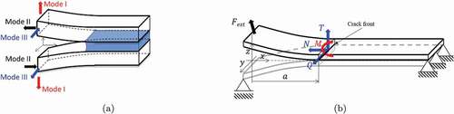
• the mode I – opening or cleavage mode and followed by notation ,
,
• the mode II–in-plane shear and followed by notation ,
,
• the mode III – anti-plane shear and followed by notation ,
,
The existing crack growth criteria[Citation95–97] are congruent and indicate mode I as the most critical loading case. Hence, the joints are designed to carry the loads corresponding to mode II and mode III loading directions and such conditions are frequently encountered in real structures. Moreover, the ‘perfect’ (e.g. pure mode I) conditions are very difficult to achieve even at the coupon-level specimens.[Citation98,Citation99] The local analysis reveals that at the crack tip mixed mode conditions exist and therefore mode-mix experimental configurations are frequently in use. Under an arbitrary external loading, (see ), for a prismatic, rectangular cross-section adherend (usually beam), using the effective crack tip forces approach, modes I, II and III can be combined through[Citation100–102]:
where ,
,
, and
are the adherend Young’s and shear modulus, adherend thickness and width, respectively.
,
and
are the bending (cleavage) moment, axial/membrane/in-plane force and transverse/out-of-the-plane shear force per unit width, respectively, and
is the transverse/anti-plane shear force. EquationEq. 1
(1)
(1) can serve as a basis for identifying important and measurable quantities and reviewing specific loading cases.
2.3.1. Mode I
In this case, and
, leading to:
where is the edge applied bending moment or the effective bending moment defined as
with
being the projected on
-axis component of
(see ) and
is the current crack length.
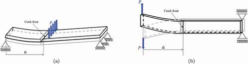
Figure 4. Schematic representation of the DCB (a) and the TDCB (b) specimens with initial crack of length , under transverse force,
, or displacement,
loading (adopted from[Citation103]).
![Figure 4. Schematic representation of the DCB (a) and the TDCB (b) specimens with initial crack of length a0, under transverse force, P, or displacement, Δ loading (adopted from[Citation103]).](/cms/asset/4677fd46-cd59-42bd-ad9f-cf39066d80aa/gadh_a_1953479_f0004_oc.jpg)
Both, and
could be applied to the tip of the adherends and both such loading conditions are now frequently in use with the latter case being subject of standardized method[Citation104] with the data reduction following bending of a cantilever beam. The family of methods is known under the name of Double Cantilever Beam tests (DCB), [Citation10,Citation105] , which forms the most widely used testing framework. Here, three types of loading boundary conditions are usually considered:
(a) loading with the bending moment ,
(b) loading with the transverse force (at constant displacement rate, i.e.
),
(c) loading by imposed constant displacement where
can be regarded as reaction.
a) Loading with bending moment: Experiments are controlled by direct application of which needs to be measured directly (torque sensors)[Citation106] or indirectly. In the latter case, over the time authors developed different strategies aiding direct application of the loading moment.[Citation107,Citation108] However, universal tensile machines require adoption and additional elements like brackets, pulleys and wires[Citation109,Citation110] to convert transverse machine cross-head motion into moment loading. Also, part of the specimen needs to be sacrificed as special adaptors are also required for the specimen. Due to that, the method using applied moment is frequently used for wind industry applications where the coupon-level specimens are usually much bigger than the one used in e.g. aerospace (meter vs. centimetre scale). Adaptation of the
integral approach[Citation111,Citation112] leads to another interesting relation:
where is the rotation of the loaded tip which can be measured directly, through e.g. inclinometers, image correlation, or evaluated from the measured displacement. The advantage of the moment-controlled experiments is theoretical insensitivity to the crack length, i.e.
. Since this is the case, it allows easy and reliable evaluation of the crack tip stresses, following
which is advantageous for extracting cohesive zone parameters.[Citation113]
b) Loading with transverse force: Application of transverse force results in an effective bending moment at the crack tip so that
. For
to be the dominant loading component requires the substrate to be slender – i.e. the initial unbonded part of joint, or the initial crack front
, must be at least
. If e.g. composites are being used, an additional consideration must be given to material properties as material are no longer isotropic, and in general
in Equationeq. (1)
(1)
(1) . If the slenderness condition is not fulfilled the second component,
, must be included and data reduction becomes more tedious.[Citation114,Citation115] To facilitate treatment a number of corrections are proposed.[Citation116–118] During the test, force
and the crack length
needs to be measured simultaneously to evaluate
. While
is measurable in a straightforward manner (force sensor), measurements and interpretation of
is less obvious and debatable .[Citation119,Citation120] The popular way of direct measurement of
is by side observation using travelling video cameras.[Citation104,Citation121] Following such protocol standards, that have been already established for testing of fiber reinforced composites (see e.g.[Citation122,Citation123]), are largely adapted for testing of adhesively bonded composite joints. Over the time, different strategies have been adopted for more reliable measurements, incl. strain gauges, [Citation124,Citation125] optical and fibre Bragg grating sensors, [Citation126,Citation127] acoustic methods[Citation128] or digital image correlation[Citation129–131] to name a few. Importantly, a large number of protocols, based on e.g. beam and plate theories have been proposed to link
to an easily measurable vertical displacement of the load application point
. This allows for plotting the load-response, or the force law, or the
vs.
curves forming a very popular approach. Additional work in this field has been done on high-rate fracture testing to study rate effects on the adhesive fracture toughness. Many studies were performed for mode I and detailed procedures were developed.[Citation132–136] A similar DCB framework is used for fatigue studies; however, a choice of loading conditions and, thus, definition of the loading ratio can be cumbersome due to the prismatic beam geometries[Citation137–139] and hence the lap joint geometries are often preferred.[Citation140–142]
An important approach aiming in relieving from crack length dependence is Tapered DCB (TDCB)[Citation143,Citation144] schematically shown in . Following Equationeq. (1)
(1)
(1) and taking
the DCB
. Thus, once
the
becomes independent of the crack length guaranteeing a constant bending moment at the crack tip. This approach has received noticeable attention and has been used by the aerospace industry for fatigue testing as, contrary to the DCB geometry, the TDCB and the constant moment conditions allow controlling the amplitude and the loading ratio during the course of the entire test.[Citation133,Citation145,Citation146] The drawback is the manufacturing of tapered geometries especially when using composites. In addition, the varying thickness is likely to affect stress state inside the adhesive. Importantly, so far, only BS 7991[Citation147] an ISO 25217[Citation148] specify test procedure for mode I testing of composite/composite joints using double cantilever beam (DCB) or the tapered double cantilever beam (TDCB) specimens under quasi-static loading. No standards for other loading patterns have been developed yet.
c) Loading by imposed displacement: To reduce the overall costs of testing, by excluding use of any machines, and address the need to study durability of bonded joints an edge applied displacement loading has been proposed.[Citation124,Citation149–151] Here, one introduces a spacer/wedge or rod between the two adherends and follow the increasing crack length. Such approach, using a wedge, was later pursued by Boeing company engineers and constitutes a separate standard method, [Citation152,Citation153] which, however, can be only used for qualitative comparisons. More recently, few methods and data reduction schemes have been proposed to address this issue.[Citation154,Citation155] Due to the stability of the crack growth process – once the crack onsets the , the wedge configuration is very suitable for dynamic loading. ISO Impact Wedge-Peel test (IWP) provides information on the behaviour of different adhesive/adherend combination. The IWP test was proposed as an International Standard in 1993, [Citation156] and it suggests the use of 20 mm wide sheet metal adherends (between 0.6 and 1.7 mm thick) with 90 mm long and bonded over a length of 30 mm. The free arms of the specimen are clamped, and a wedge is driven through the bonded portion. The velocities recommended are 2 m/s for steel adherends, and 3 m/s for aluminium. This standard is popular for automotive industry in order to evaluate the relative performance of adhesives.[Citation157–159]
2.3.2. Mode II
Introduction of pure mode II requires the crack tip force coming solely from the horizontal projection, along the -axis, of
which at the crack tip decomposed into
and
. Here
and
are the axial forces acting on the upper and bottom adherends respectively. Direct application of such boundary condition rarely takes place and is a domain of ‘stress’ testing, incl. shear lap joints. The fracture mechanics implementation is based on the beam bending configurations applied to bonded joints and have been reviewed on several occasions.[Citation160–163] For instance, the three-point bending test on bonded joints with an edge crack corresponds to the End Notched Flexure (ENF) experiment shown in , the cantilever beam test applied to the edge crack specimen corresponds to the End Loaded Split (ELS)[Citation164–166] experiment or inverted version of such (iELS).[Citation119,Citation167]
Figure 5. (a) ENF mode II testing configuration and (b) Split Cantilever Beam for mode III testing.
The four-point bending tests performed on bonded and crack configuration correspond to 4ENF, e.g. [Citation168] We consider ENF as the most popular, and the only standardized version of mode II experiment. Here, the loading is due to the transverse force which is applied in the middle of edge-cracked specimen. Under such conditions, following Equationeq. (2
(2)
(2) ),
, so that
and
should be measured. As previously, the fact that
is used. Popular mode II tests ENF and ELS often encounter instabilities .[Citation169,Citation170] Under such circumstances overall reliability of mode II testing can be questioned. In addition, since all configurations are loaded by transverse forces, compressive stresses at the crack tip[Citation171,Citation172] are introduced which can alter estimated values of SERR. Since the crack faces are compressed and under shear loading, the effect of friction should be taken into account.[Citation173,Citation174] In addition to the aforementioned tests, a number of
integral approaches are being introduced into mode II testing. The loading conditions are not necessarily affected, but the measured quantities and such tests usually require additional instrumentation.[Citation175]
2.3.3. Mode III
Compared to the other fracture modes, a relatively small amount of works considered mode III. The importance, specifically from the applied perspective, is indisputable. Several test methods were examined as ways to measure interlaminar mode III fracture toughness. Agarwal and Giare[Citation176] carried out tests on short-fiber composites using a single notched plate arrangement. Such configuration, under the name Edge Crack Torsion[Citation177] has been applied to the bonded joints[Citation178] to study rate effects in mode III. Main drawback these tests suffer from is distortion due to the relatively low torsional rigidity of plates geometries. To address this issue, Ripling et al.[Citation179] used a modified DCB arrangement under with the loads applied in the crack plane but in transverse direction (thus anti-plane shear mode). The name coined for such configuration is Split Cantilever Beam[Citation180] shown schematically in . Due to the robustness – universal tensile machine is easily adopted, and the data reduction follows one of the DCB, which has been used on many different occasions. In the work by Szekrenyes,[Citation181] the author analysed the configuration using shear deformable beam theories, and in the work by Budzik et al.[Citation125] effects of the process zone have been quantified. Ever increasing demand for more reliable structures but without compromising on mechanical performance is reflected by the increasing number of newly proposed configurations.[Citation182–184]
2.3.4. Mixed-mode
Strive for more reliable design tools, more robust failure criteria, and experimental campaigns simulating as close as possible actual loading conditions, led academia and industry towards mixed-mode fracture testing. The need for such an approach comes from the fact that, usually, structures experience complex loading scenarios during operations and life-time. In addition, even predominantly pure fracture loading lead to mixed-mode conditions at the crack tip.[Citation99,Citation185,Citation186] Straightforward addition of the pure modes’ contributions does not yield correct results and a number of models have been provided to facilitate calculations.[Citation187–189] Since three basic modes exist, a total of four mixed-mode conditions could be outlined: I/II, I/III, II/III and I/II/III. All of these cases have been investigated experimentally. The most widely used conditions correspond to I/II. The popular configuration refers to the asymmetric bonded joint. Here, two dissimilar materials in terms of bending stiffness ( where
is the adherend Young’s moduli and
is the second moment of the cross-section area) are bonded to produce a specimen similar to the DCB and referred to as ADCB. Due to the difference in bending stiffness under loading, the two adherends bend, rotate and displace by different amounts, thus leading to mixed conditions at the crack tip.[Citation190,Citation191] Basic data analysis follows the one outlined previously for the DCB, which here however evaluated
corresponds to
. Once the stiffness of one of the adherends
a single cantilever beam geometry (often referred to as SCB) is produced.[Citation192] This geometry is very popular due to the simplicity of the data reduction and is probably the only choice for testing bonding between ‘flexible’ and ‘fragile-rigid’ materials, i.e. encountered in electronics.[Citation193,Citation194] Combination of the DCB and the ENF produces a mixed-mode bending (MMB) test.[Citation162,Citation195–197] The test gains significant importance and is one of the standards in the aerospace industry. Advantages here are easiness of producing different modes
ratios, which together with the DCB and the ENF can form the so-called fracture envelope.[Citation198] More recently Blackman et al.[Citation134] investigated the dynamic behavior of composite joints under mode II and mixed mode I/II. Mixed mode I/III conditions are probably the second most extensively studied due to the fact that a number of mode III deemed configurations in reality introduce mode I as well. Like in the previous case, the privilege is given to the beam like geometries due to their simplicity, data reduction schemes and previous experiences with mode I and II testing.[Citation199–201] The literature on modes II/III and I/II/III is still very limited, though seems to be very important due to the expectation, as mode III introduces additional edge debonding or delaminations so that the coupling between different delaminations is of interest.[Citation202,Citation203] For instance, some authors proposed a combination of the ENF with an out-of-plane shear loading to study mode II/III fracture on a prestressed material system.[Citation204] De Morais and Pereira[Citation205] studied mode II/III fracture but in the context of delamination and using a six-point bending plate (6PBP) specimens. Davidson et al.[Citation206,Citation207] further developed the MMB configuration and added out-of-the-plane shear displacement to study I/II/III modes combination.
2.4. Other relevant aspects
2.4.1. Adhesive thickness
The thickness of the bondline (denoted as in and ) is one of the crucial geometrical parameters of an adhesively bonded joint. The role of
on local, crack tip vicinity, strain and stress distribution is depicted by .
Figure 6. Adhesive thickness affects the local, crack front, stress/strain field. The color map corresponds to the strain tensor shear component
captured using the digital image correlation. Predicted distribution of the crack opening stresses
is also presented. (Courtesy of Michal K. Budzik).

Historically, bondline thickness was often assumed as negligible when compared to other important length scale parameters; thus, for analysis the effect of the bondline thickness could be omitted – such case is present on the left side of . Application of adhesive joints in marine, civil engineering, or wind energy industries requires use of thick adhesive layers, up to several centimetres[Citation208,Citation209] for which excluding adhesive thickness seems inappropriate – such case can be seen on the right side of . Irwin[Citation210] and Orowan[Citation211] introduced corrections recognizing that the plastic zone ahead of the crack tip can dominate the evaluated fracture energy of many structural materials.[Citation212] The concepts of the process zone, fracture process zone, plastic zone and related corrections leading to a more reliable estimation of e.g. fracture energy was further exploited and applied to adhesive bonding.[Citation213–215] For instance, the original Irwin idea of the plastic zone in front of the crack tip has been associated with a finite stiffness of the adhesive layer.[Citation216–219] Following these approaches the adhesive layer thickness was introduced explicitly to the original formulations neglecting finite stiffness of the region ahead of the crack tip. The research devoted to the adhesive layer thickness and its effects is considerable[Citation220–227] as few examples. Various, contradicting results are obtained. For instance, in the work by Kawashita et al.,[Citation224] the authors analysed the effects of bondline thickness using peel experiments without observing any clear trend indicating dependence between the adhesive thickness and the fracture energy. Additional results obtained through the TDCB experiments revealed an increase in fracture toughness with the bondline thickness. In the work by Davies et al.,[Citation225] effect of adhesive thickness is studied using a variety of physico-chemical and mechanical methods, thus searching for a link between the mechanical response, bondline thickness and reactions taking place during curing of differently confined adhesives. In[Citation228] the results indicate increase in fracture toughness until certain limiting thickness above which the apparent toughness converges. Such effect was associated with the radius of the plastic zone ( where
is the adhesive Young’s moduli and
is the adhesive failure stress). Therefore, it is deemed that the plastic zone cannot develop once the bondline is too thin,
, and, hence, altering the energy dissipation. In[Citation229] similar results were obtained, with non-convergent fracture energy for thick bondlines being recorded. In[Citation230] the effect of adhesive thickness on the parameters of traction-separation law (TSL) was investigated. Increase in the thickness lead to higher critical opening at the crack tip, thus leading to increase in the fracture energy. In the work by Arenas et al, [Citation226] the authors aimed in optimizing the thickness of the bondline following the data obtained from the shear lap joint experiments and Weibull statistical treatment. In this case, the strength decreases with the adhesive thickness; however, the Weibull modulus, carrying information about the reliability of the structure/material, does not show a clear trend. The adhesive thickness effect can be directly related to the stability of the crack growth.[Citation231] Another important aspect is related to the fact that by increasing the thickness of the adhesive layer the corner singularities are developed between the adherend and the adhesive.[Citation232–234] For instance, the confinement of the bondline alters development of the process zone including the plastic zone.[Citation235,Citation236] With the focus shifting recently towards bimaterial bonded joints, the effect of adhesive thickness will continue to be very important for the failure loads and loci.[Citation100,Citation237,Citation238]
2.4.2. Dissimilar adherends
Bonding and evaluation of structures and materials made of dissimilar adherends is gaining nowadays significant attention.[Citation237,Citation239,Citation240] It is well recognized that once a bimaterial is loaded, a stress gradient exists at the interface between the two materials.[Citation241] Under such circumstances, the structure, or material, is likely to fail under apparent loading being lower than the failure load calculated for any of the two materials separately.[Citation236] The adhesive thickness may play here a significant role, as the adhesive itself can form the ‘dissimilar’ interface, providing it is thick enough (like on the right side of ) or it can be treated as a line which accommodates the stress gradient between the two joined materials. The latter problem received attention from the theoretical standpoint and led to the nascent of the interface fracture mechanics.[Citation100] The data here were often supported by the experimental investigations using so-called Brazilian disc test, [Citation242] however, it is only recently that the scientists start to work on it motivated by industrial needs. Indeed, composite patching of aluminium fuselages or concrete bridges, or attaching composite superstructures to steel decks are examples of bonding between two dissimilar adherends. Another interesting aspect is related to assuring controlled loading conditions in bimaterial joints. For instance, in the work by Budzik et al.,[Citation172] strain has been used to detect deviations from the pure mode II loading conditions. Recently, in the work by Wang et al.,[Citation240] the authors proposed a strain-based criterion to produce mode I conditions at the crack tip in bimaterial joints. This analytical methodology was also recently applied for mode partitioning in mixed mode bimaterial joints.[Citation243]
3. Applications
This section summarizes the frequently used methods to test and evaluate mechanical performance of structural adhesive joints in the aerospace (Subsection 3.1), wind energy (Subsection 3.2), civil engineering (Subsection 3.3) and automotive (Subsection 3.4) industrial sectors using or aiming to use adhesively bonded connections. Preference is given to structural applications of adhesive bonding emphasizing aspects like the use of composite materials and bi-material systems or effect of adhesive thickness. Industry-specific aspects regarding structural applications are also outlined.
3.1. Adhesive joints in aerospace engineering
3.1.1. Potential and challenges
In aerospace applications, the use of adhesive bonding has been increasingly growing since it was first introduced in 1945.[Citation16] Adhesive bonding, of both metallic and composite materials, has been utilized for primary structures such as fuselage and wings in the form of skin–stringer, skin–rib and skin–spar joints.[Citation244] Despite the fact that adhesively-bonded joints represent a great potential in the aerospace industry, there are various limitations and challenges facing the further expansion and utilization of them. The quality and strength of adhesively-bonded joints, especially for composite materials, relies on many parameters, some of which are design-driven, [Citation16,Citation245–250] such as the geometrical parameters, materials to be joined and the adhesive characteristics, while others are manufacturing and process-driven, [Citation244,Citation251–253] such as the surface pre-treatments, the bonding area and the effect of defects. In fact, the preparation of any surface involves not only cleaning, but also its treatment, which must consider the combination adhesive/material of the adherend.[Citation254–257] For this purpose, chemical and/or mechanical treatments are generally used to improve the surface performance of adherends. According to Molitor et al., [Citation258] while the traditional abrasion and solvent cleaning techniques are sufficient for thermoset composites, thermoplastic ones require surface chemistry and surface topographical changes to obtain strong and durable adhesive joints. Acid etching, corona discharge treatment, plasma treatment, flame treatment and laser treatment are examples of surface treatments that aim to decrease the water contact angle and increase the surface tension.[Citation258,Citation259] In terms of aluminium alloys, Critchlow and Brewis[Citation260] presented a review of surface treatments, which involved mechanical, chemical or electrochemical treatments. These authors concluded that, regardless of its effectiveness, the surface treatment must be selected according to the type of aluminium and adhesive to obtain the highest strength and durability. In addition, surface treatments are strongly suggested to obtain a strong interface between adhesive and adherend to prevent the displacement of the adhesive by water, [Citation260] as well as for production of fibre-metal laminates (FML) components.[Citation261] Another challenge of using adhesively-bonded joints, especially those made of composite adherends, is exploiting their full load-carrying capacity. In the case of compression of thin-wall panels for instance, metals are allowed to buckle as their response is well understood, offering significant weight reductions when it comes to design.[Citation253] On the contrary, the large out-of-plane deformations associated with buckling result in excessive delaminations in composite structures leading to debonding and consequently final failure. For composite stiffener/skin structures, the failure load of such panels may be two times more than the buckling failure load.[Citation262] However, these structures are designed only up to the buckling load due to lack of good prediction of post-buckling behaviour of these structures. In order to achieve the maximum efficiency of the post-buckled structures and access this reserve of the post-buckled strength, deep understanding of the post-buckling response and collapse behavior, including damage mechanisms, is essential. Thus, several attempts by researchers are reported in literature to accurately predict and capture the post-buckling and damage progression in such skin-to-stiffener joints by numerical modelling.[Citation245,Citation247,Citation249,Citation263–269] Due to the complexity of simulating some of these sub-components, researchers used a hybrid global-local finite element analysis.[Citation249,Citation250,Citation265] This approach leads to a cost-effective analysis with no compromise of the accuracy of the simulations, but it is out of the scope of the current piece of work. In spite of all the efforts exerted so far in the modelling, there is still a quite limited confidence when it comes to the development of generic models that can be directly applied in real-life applications. Such a lack of confidence in having robust predictive models means that qualification and certification of adhesively-bonded composite structures is both cost and time consuming, as extensive coupons and elements testing is necessary.[Citation248] In addition, this lack of confidence forces the safety authorities to include mechanical fasteners as an additional safety measure which results in highly inefficient structures.[Citation251] The situation becomes more complicated when it comes to the qualification of new adhesives for bonded joints in the aerospace industry. Nowadays there are two adhesive systems used for bonding in aerospace industry: phenolic and epoxy systems. Both systems demonstrate good resistance to fluid immersion tests with the phenolic performing better in high humidity and high temperature environments.[Citation16] The qualification process of new adhesives is a tedious process involving more fluid immersion, thermal fatigue and accelerated ageing followed by static and fatigue structural testing. For aircraft industry, literature reports that new adhesive systems should be assessed based on their durability and long-term performance, rather than just relying on the static properties.[Citation16,Citation270] Testing by soaking in warm water (35C) for periods as long as (1000 hours) or high humidity and temperature testing (95
RH and 70
C) is used to simulate typical environmental conditions which such structures experience in service.
This section presents an overview of the trends in testing and characterization of adhesively-bonded joints for aerospace applications while shedding the light on the importance of the careful consideration of the design and manufacturing aspects and their effect on the structural integrity and strength of the joints. Moreover, it discusses the effects of defects on the adhesively-bonded joints, regardless of the nature of it being a manufacturing or an in-service defect. Finally, it concludes with highlighting the potential of relying more on adhesively-bonded joints in aerospace structures.
3.1.2. Trends in testing
As previously highlighted, one of the main challenges, facing the wide-spread usage of bonded joints, is the extensive testing and characterization required to fully understand their behavior under various loading conditions. Testing a full-scale structure is very costly and time consuming. On the other hand, coupon testing is sufficient for material properties’ characterization but does not always provide information regarding the joint behavior under the actual conditions experienced by structural components during operation. Thus, the real challenge is always to develop element/sub-component test set-ups which mimic the geometrical constraints and the load transfer in full-scale structures. These sub-component elements generally consist of a section taken through a single or multiple stiffeners and can be tested in fairly large numbers.[Citation253] shows typical profiles used for stiffeners, such as I, T, L, J and hat profiles.[Citation249]
Figure 7. Typical stiffener profiles used to reinforce panels of aerospace structures.
Generally, there are two locations in the stiffened panels which are more susceptible to damage/failure initiation either at the tip of the stiffener foot or at the core/noodle region – see .[Citation253]
Figure 8. Principal damage onset locations for skin-to-stiffener joints – stiffener core or noddle and stiffener tip.[Citation253]
![Figure 8. Principal damage onset locations for skin-to-stiffener joints – stiffener core or noddle and stiffener tip.[Citation253]](/cms/asset/5df2c1ba-91cf-41db-81c6-c3d942ca1392/gadh_a_1953479_f0008_b.gif)
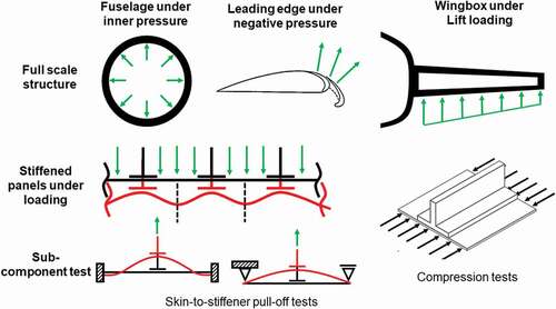
The former is the dominant and most important failure mode, and it occurs mainly due to large deformations, caused by global buckling of the structure, leading to delamination at the interface and ultimately final failure. The latter is associated to the out-of-plane loading of the stiffener’s web due to pull-off loading. Several testing procedures are available to characterize such stiffened panels under tension, compression, bending, buckling and post-buckling loading conditions. shows two typical sub-component tests performed in adhesively bonded joint for aerospace structures: skin-to-stiffener pull off-test and compression tests of stiffened panels. In order to simulate out-of-plane loading conditions, such as internal pressure of the fuselage or the low pressure zone at the leading edge, pull-off tests[Citation245,Citation246,Citation251,Citation263,Citation267,Citation271–274] of skin-to-stiffener joints are implemented.
Figure 9. Schematic representation of the sub-component tests representing the loads and boundary condition of the full-scale aerospace structures under service.
These tests allow the evaluation of the performance of different design concepts and structural features in skin-to-stiffener joints by applying tensile loading on the stiffener’s web while fully supporting the foot/skin from the edges. and show examples found in literature of pull-of-tests using T-type and L-type stiffeners, respectively.
Figure 10. Pull-off test setup: Fiber Metal Laminate skin bonded to a CFRP T-stiffener.[Citation64]
![Figure 10. Pull-off test setup: Fiber Metal Laminate skin bonded to a CFRP T-stiffener.[Citation64]](/cms/asset/fdb1b146-07e8-468b-9c09-1d11238f6cb3/gadh_a_1953479_f0010_b.gif)
Figure 11. Pull-off test setup with CFRP skin bonded to an aluminium L-type stiffener[Citation273].
![Figure 11. Pull-off test setup with CFRP skin bonded to an aluminium L-type stiffener[Citation273].](/cms/asset/b27ff364-1624-4f43-a451-da0cba645045/gadh_a_1953479_f0011_oc.jpg)
Both examples use fully clamped boundary conditions at the skin longitudinal edges. Simply supported edges have also been reported but the latter boundary condition yield to lower pull-off loads than the fully clamped one.[Citation271] From these tests, the failure sequence and failure modes can be identified as well as the load carrying capacity, which in return helps the designers predict the behaviour of the full-scale structures, as exemplified in . Teixeira de Freitas et al.[Citation245] reported that when testing CFRP T-stiffeners bonded to a FML skin using pull-off tests, the damage onset occurs at the stiffener noodle, while if using an Aluminium T-stiffener, the damage onset occurs at the stiffener tip – see .
Figure 12. Damage evolution of a FML skin bonded to a CFRP T-stiffener (a) and an aluminium T-stiffener (b) under pull-Off test.[Citation245]
![Figure 12. Damage evolution of a FML skin bonded to a CFRP T-stiffener (a) and an aluminium T-stiffener (b) under pull-Off test.[Citation245]](/cms/asset/194748ee-8c82-4ece-a517-260fce5578de/gadh_a_1953479_f0012_b.gif)
However, literature reports that in full-scale compression tests of CFRP panels the damage onset tends to occur at the stiffener foot tip and not at the noodle region, [Citation253] as shown in . Therefore, alternatives to the pull-off test have been investigated to induce damage initiation at the stiffer foot tip, to mimic the damage scenario of the full-scale structures. shows some of these examples, where the skin-to-stiffener joint is subject to bending[Citation264,Citation275] and/or tension[Citation252] in which stiffener foot tip failure is induced.
Figure 13. Test setups for characterizing skin-to-stiffener joints which induce stiffener foot tip failure.[Citation253]
![Figure 13. Test setups for characterizing skin-to-stiffener joints which induce stiffener foot tip failure.[Citation253]](/cms/asset/3877e6c3-2651-4bfe-93e8-92d6e745aee4/gadh_a_1953479_f0013_b.gif)
The same type of tests has been also performed on L-type stiffeners with the same purpose – see examples in .
Figure 14. Single L-type stiffener structures under bending (a) and tensile (b) tests.[Citation275,Citation276]
![Figure 14. Single L-type stiffener structures under bending (a) and tensile (b) tests.[Citation275,Citation276]](/cms/asset/4bba792d-f605-41e5-9619-1dad3944caea/gadh_a_1953479_f0014_oc.jpg)
As far as the compression testing is concerned, [Citation252,Citation253,Citation262,Citation268,Citation277,Citation278] these tests are used to evaluate the effectiveness of the adhesively-bonded joints, in maintaining the structural integrity, in the case of buckling and post-buckling. This serves one of the main objectives of attaching stringers/stiffeners to the skin of fuselage or wing structures, aiming to provide the required strength against buckling loads in service.[Citation16] These tests can include a single-stiffener or multiple stiffeners in parallel, as shown in .
Figure 15. Specimens for compression tests with single (a) and multiple stiffeners (b).[Citation268,Citation277]
![Figure 15. Specimens for compression tests with single (a) and multiple stiffeners (b).[Citation268,Citation277]](/cms/asset/16fd5d6a-2081-409b-8c1f-e44b5a90cc35/gadh_a_1953479_f0015_oc.jpg)
3.1.3. Other relevant aspects
3.1.3.1. Effect of design and manufacturing parameters
Optimization of the adhesively-bonded joints’ strength relies on different design and manufacturing parameters, some of which, are discussed here. These parameters cover a wide range of choices, from the selection of: the adhesives’ and adherends’ material, their geometrical design, the surface pre-treatment of the adherends, the termination of the connection between the stiffener and the skin “i.e., fillet and run-out design”, and the spacing between the stiffeners in the actual component. For instance, stress concentrations normally occur at the free edges of the bonding areas in adhesively-bonded joints. Using ductile adhesives can help reducing such stresses leading to a better macroscopic/global performance. In the case of pull-off testing, researchers[Citation246,Citation247] reported the advantages of using flexible adhesives, such as Sikaforce 7752, over brittle Araldite adhesives, for spreading the load over a larger extension and dissipating more energy during damage before final failure. It was shown that the ductility of the adhesive can be one of the main reasons for the increase of the joint strength, showing that a less strong but ductile adhesive can perform better than a stronger but brittle counterpart. Furthermore, Akpinar et al.[Citation266] used a novel technique by combining a stiff and a flexible adhesive (DP460 and SBT9244) along the overlap length showing that such bi-adhesive joint design was effective in improving the joint strength by 20 compared to the strength of the joints being made out of each of the adhesives separately.
Another technique, to reduce the stress concentrations at the free edges, is to optimize the fillet design[Citation262,Citation276] successfully demonstrated that the post-buckling behavior and the failure mechanisms can be altered by flange tapering (see ), leading to interlaminar delamination of the composite at the free edge with mostly no observed debonding between the stiffener and the skin.
Figure 16. Examples of tapered stiffeners geometry .[Citation262]
![Figure 16. Examples of tapered stiffeners geometry .[Citation262]](/cms/asset/d5dee512-2065-4fa8-9102-1a60a97d5320/gadh_a_1953479_f0016_b.gif)
In addition, Feih et al.[Citation276] reported similar failure mechanisms for the pull-off case of L-type stiffeners, as shown in . By simply changing the fillet shape from a natural flow fillet, as observed during hand assembly (), to a controlled fillet design (), an increase in the joint strength up to 100 could be achieved.
Figure 17. L-stiffener fillet design (a) controlled fillet design and (b) natural flow fillet as observed during hand assembly.[Citation276]
![Figure 17. L-stiffener fillet design (a) controlled fillet design and (b) natural flow fillet as observed during hand assembly.[Citation276]](/cms/asset/a672c1cd-d2c6-4291-aab1-fd1f56e70ef6/gadh_a_1953479_f0017_oc.jpg)
Another geometrical factor, that has been extensively studied, is the run-out of stringers/stiffeners – see , at locations where the load path is interrupted due to structural conflicts with the adjacent regions or due to rib intersections or access holes.[Citation248–250,Citation265,Citation279]
Figure 18. Stiffener run-out location and different geometry types (a) location of run-out region and (b) Run-out geometries.[Citation248]
![Figure 18. Stiffener run-out location and different geometry types (a) location of run-out region and (b) Run-out geometries.[Citation248]](/cms/asset/e63fb912-09de-4da0-904d-d95610eebdc2/gadh_a_1953479_f0018_oc.jpg)
Figure 19. Type A joint and Type B joint, representing wide and narrow skin bays between stiffeners, respectively.[Citation274]
![Figure 19. Type A joint and Type B joint, representing wide and narrow skin bays between stiffeners, respectively.[Citation274]](/cms/asset/56727723-02a1-4b0c-802a-7c7807abcc76/gadh_a_1953479_f0019_oc.jpg)
At the location of the run-out, the loads are directly transferred from the stiffener to the skin leading to high stress concentrations that make such regions prone to premature failure. Using a parametric FEA, Psarras et al.[Citation279] showed that by optimizing the run-out design, an improved stable crack-growth, under uni-axial compression, was obtained. Moreover, the failure mechanism changed from a skin-stiffener debonding in the baseline case to an interlaminar delamination in the stiffener between the and
plies leading to a catastrophic failure. Reinoso et al.[Citation249,Citation250] investigated the effect of different run-out designs on the tensile and compressive response of composite skin-stringer joints. In compression, the out-of-plane deformation led to the skin-stringer debonding around the run-out region; however, the damage initiation and propagation path demonstrated a significant dependency on the run-out design. Experimental observations suggested that the load levels, for the damage initiation and final failure, differ from one design to the other. Authors attributed this to the fact that the local stress state, around the run-out region, was the main cause of the damage initiation and failure in the form of stringer-skin debonding and localized intralaminar delamination at the outer surface of the composite panels. Careful selection of the adherends has been proven to play a major role not only in the joint strength, but also in the damage and failure modes. Teixeira de Freitas et al.[Citation245,Citation267] studied the difference between metal-to-metal joint and a metal-to-composite joint when subjected to both quasi-static and fatigue pull-off tensile loading. The failure in the metal joint was 100
cohesive failure in the adhesive bondline. However, in the case of the metal-to-composite joint, more than 90
of the failure was inter/intralaminar failure with very limited areas (
) of cohesive failure through the adhesive bondline. In the metal-to-metal joint, failure started from the tip of the stiffener foot – see . In the metal-to-composite joint, the failure started at the stiffener noodle and propagated through the stiffener foot – see ). In this case, it was clear that the CFRP stiffener represented the weakest link in the adhesively-bonded joint. Thus, it was concluded that unless the composite’s inter and intralaminar strength is improved, the aluminum stringers/stiffeners will always have an edge in the aerospace industry. The effect of surface preparation pre-treatments goes along smoothly with the choice of the adherends’ material. In the case of aluminum, for instance, a well-established standardized procedure has been in place for the lifetime of using them in adhesively-bonded joints in the aerospace industry. This procedure involves anodization and coating with a chromated epoxy/phenolic primer.[Citation16]
For composite adherends, Cardoso et al.[Citation251] investigated the effect of: i) abrasion with grits silicon carbide sandpaper followed by acetone cleaning, and ii) a nylon peel ply layer, cured with the stiffener foot and upper skin and only removed before the bonding, on the tensile pull-off strength. The peel ply-treated specimens had the least strength (
60
) compared to the untreated case, while the abraded counterpart had a slight enhancement (
5
). In the peel ply case, failure was partly cohesive partly adhesive, with large areas of macro-voids, but in the other two cases inter/intra-laminar failure of the CFRP skin was also observed. Researchers investigated also the effect of various design parameters, such as: the adherends’ thickness, [Citation246,Citation247,Citation269] the size of the bonding area, [Citation263] geometry of the adhesion zone, [Citation280] joint design[Citation270,Citation281] and composites’ stacking sequence, [Citation274] on the structural behavior and damage/failure mechanisms of adhesively-bonded joints on the sub-component level under tensile, compressive and bending loading conditions.
Justo et al.[Citation274] investigated further the effect of the spacing between the stringers to mimic two geometrical definitions: Type-A configuration which was equivalent to panels with a wide skin-bays between the stringers and Type-B configuration representing specimens with narrower skin-bays between the stringers – see . They concluded that such design parameter significantly influenced the initial failure location as well as the posterior damage propagation path.
Zhan et al.[Citation263] tested five topologies of skin-to-stiffener joints, shown schematically in , under pull-off load.
Figure 20. Five skin-to-stiffener joint topologies (dimension in mm).[Citation263]
![Figure 20. Five skin-to-stiffener joint topologies (dimension in mm).[Citation263]](/cms/asset/e40e6daa-8cd3-417f-bff6-06486aea0a16/gadh_a_1953479_f0020_b.gif)
They concluded that the failure load increases with the bonding area. However, horizontally located bondline has a better ability to increase the carrying capacity than that of the vertically located bondline.
3.1.3.2. Effect of defects
The structural integrity of adhesively-bonded joints in aerospace applications can significantly be affected by the existence of defects. Such defects can occur during the manufacturing process or during the service life of the structure/component. Therefore, adequate attention should be drawn to the experimental characterization of the effect of defects on the reliability of these joints. Guo et al.[Citation244] studied the effect of manufacturing defects on the strength of T-joints in a pull-off test. As cutouts, in aircraft structures, are unavoidable, they tested sandwich T-joints with and without a cutout in the web panel – see .
Figure 21. Sandwich T-joint with cut-out at web panel (a) and cross section detail and loading (b) (dimensions in mm).[Citation244]
![Figure 21. Sandwich T-joint with cut-out at web panel (a) and cross section detail and loading (b) (dimensions in mm).[Citation244]](/cms/asset/87c35d9e-2d6d-4ccc-8116-98d0376355a9/gadh_a_1953479_f0021_oc.jpg)
A reduction of 25
in the strength was reported due to the cutout. However, failure was still mainly due to the induced stresses in the adhesive at the base of the T-joint, in other words at the stiffener-skin interface. After failure, they proposed a repair scheme, in dry conditions using paste adhesive, which proved its success in not just restoring, but also exceeding the original joints loading capacity. Greenhalgh et al. and Meeks et al.[Citation252,Citation253] investigated the effect of manufacturing defects in the form of an inclusion embedded during the fabrication process as well as in-service defects in the form of impact damage due to tool drop on the post-buckling behavior of CFRP stringer-stiffened panels. In addition, they investigated the effect of the damage location by studying two cases; one within the bay between stringers and the other beneath the stringer foot. They concluded that the presence of defects did not change the buckling strains for all panels; however, the strength was significantly affected in some cases. In the case of impact damage, when the joint was impacted at the bay region, the strength reduction was 7
, while if the impact was on the foot region, the strength reduction was 29
. A similar trend was observed for the artificial damage cases; (
12
) reduction for the bay impact and (
23
) reduction for the foot impact. When it comes to the failure analysis, they reported that only the foot-impacted case did not suffer from skin-stringer detachment. Another way to interpret the results was to compare the effect of the defect based on its location: bay vs. foot. For foot defects, impact was found to be worse than an embedded defect, whilst for bay damage this effect was reversed. It can be therefore concluded that the defect location (bay vs. foot) is as important as the defect type itself.
3.2. Adhesive joints in wind energy
3.2.1. Potential and challenges
According to reports on failure rates of wind turbines, blade issues contribute substantially to their failure rate, and yet, reports on structural failures of rotor blades are rarely published in scientific literature mainly due to confidentiality issues. Only a few studies are available regarding failure of rotor blades with known properties and conducted in laboratories. Today, it is generally accepted that adhesive joints and in particular the trailing edge joint may seriously compromise the structural integrity of blades. However, most of the existing knowledge regarding the behavior of adhesives and adhesively bonded connections in wind turbine rotor blades comes from tests executed under well-controlled laboratory conditions and no study exists (at least in the open literature) analyzing the structural behavior of adhesively bonded connections in wind turbine blades under realistic environmental conditions, i.e., mechanical loading in combination with extreme temperature and humidity ranges.
The thickness of adhesive bondlines in large wind turbine rotor blades (WTRBs) can reach or exceed 20–30 mm in several areas to compensate for manufacturing tolerances.[Citation282–285] Two-component paste adhesives are used for such joints, and due to the common fabrication procedures, the resulted bondlines contain a significant number of fabrication defects (voids). It is expected, however, that with modern technologies for mixing and dosing the void content can be significantly reduced. Investigations regarding the behavior of this type of joints, and especially the bulk paste adhesive, are very scarce in the open literature, while the same happens for works comparing the adhesive fatigue/fracture behavior obtained from bulk adhesive specimens or thick adhesively bonded joints. The economic viability of wind energy is largely dependent on the size and lifetime of the wind rotors. Larger turbines mean that less are needed for the same energy production, thereby reducing installation costs. This trend in increasing turbine size is expected to continue for the near future to maintain wind energy’s cost competitiveness and keep up with global energy demand.[Citation286] As wind turbines continue to grow in size, the weight of the rotor and the wind loads experienced by the rotors grow at an ever-increasing rate.[Citation285] Blades grow longer and design parameters, such as blade weight, tip deflection and material cost, gain additional importance. Adhesive used in WTRBs accounts for a significant percentage of the blade weight. As reported in[Citation287] a wind turbine blade with a length of 60 meters contains approximately 500 kg of bonding paste and adhesives contributes strongly to the structural integrity. This weight accounts for more than 10 of the total blade weight although for contemporary rotor blades with weight that can reach ca. 20 tonnes, see , a lower percentage can be expected.
Figure 22. Average blade weight with rotor diameter.[Citation288]
![Figure 22. Average blade weight with rotor diameter.[Citation288]](/cms/asset/622fb141-5c88-4087-b999-4a967a6cc6bf/gadh_a_1953479_f0022_oc.jpg)
Full scale physical blade testing is the ultimate tool for the certification/validation of the blade design and manufacture. Nevertheless, current experiments performed on full scale Mega Watts wind turbine blades are very time consuming and expensive. Moreover, they are more challenging if not impossible for the academic community, as requirements for experimental facilities are very demanding and furthermore the time for performing the experimental test campaign and the cost are not well suitable for most research projects.[Citation289] Multi scale models based a) on material properties, b) on sub-component behavior, and c) on testing of down-scaled blades are used to alleviate the burden of full scale testing.
Most of the contemporary rotor blades are structures with multi-cellular thin walled heterogeneous sections made of fiber reinforced laminates bonded together by using structural adhesives.[Citation290] Different glass fiber fabrics were used for long time, due to their low cost and ease of manipulation during manufacturing. Carbon fibers were initially employed to reinforce the longer and heavier blades, used for example for the spar beams, or as external reinforcements. Hybrid composites (glass/carbon hybridization) are used today to allow the production of long blades by keeping the weight and the cost in reasonable levels. Carbon fibers can be placed locally to increase the stiffness for a given blade weight, or reduce the weight for a given stiffness.[Citation291,Citation292] Lots of research efforts have been allocated for the investigation of the performance of composite materials for wind turbine blades, see e.g., [Citation293–296] durability of structural adhesives, e.g.,[Citation297] as well the fatigue/fracture performance of adhesively bonded joints under different loading[Citation138,Citation197,Citation298–303] and environmental conditions.[Citation304] Nevertheless, less research has been performed for hybrid composites, especially their durability and long-term behaviour, although they seem to be very promising for wind energy.
The most contemporary wind turbine rotor blades are massive composite structures containing several square meters of thick bondlines, see e.g. .
Figure 23. Example of structural bond lines on two wind blade designs.[Citation285]
![Figure 23. Example of structural bond lines on two wind blade designs.[Citation285]](/cms/asset/51a62619-769a-4d5e-9f7c-59d3a3b43c4b/gadh_a_1953479_f0023_oc.jpg)
The adhesive layers that can have thickness reaching 30 mm[Citation305] usually include several local, but large, voids, as shown in [Citation306] and .[Citation307,Citation308]
Figure 24. Voids in the bonding lines of composite wind turbine blades.[Citation306]
![Figure 24. Voids in the bonding lines of composite wind turbine blades.[Citation306]](/cms/asset/494fec0c-9111-401b-b341-c1f54284e9ba/gadh_a_1953479_f0024_oc.jpg)
Figure 25. Typical wind turbine blade cross section (a) and cross section of the adhesive joint from spar cap to shear web in detail (b).[Citation307,Citation308]
![Figure 25. Typical wind turbine blade cross section (a) and cross section of the adhesive joint from spar cap to shear web in detail (b).[Citation307,Citation308]](/cms/asset/f579eae7-e8b9-4c39-b6d6-b0006e0774ac/gadh_a_1953479_f0025_oc.jpg)
Gaps as large as 12–15 mm and voids in bondlines – some up to 50 mm long – were observed in a 43 m rotor blade.[Citation309] The adhesive bonding of the different parts in a wind turbine blade provides a special challenge as it is difficult to scale down the thickness of the bondline and derive realistic scaled joints for the down-scaled blade.[Citation289] Adhesive bondline thickness of wind turbine blades is much larger, [Citation10,Citation310] hence, the problem of down-scaling for experimental investigations becomes more pronounced. Such scaling problem was identified very early by Hart-Smith[Citation16] who recognized that the behavior of typical long-overlap structural bonded joints is frequently very different from equivalent short-overlap test specimens.
Bulk adhesive behavior becomes more important with thickness[Citation311,Citation312] and in such cases fatigue data on bulk adhesives might be more reliable than those from joints.[Citation13] Nevertheless, it seems that for thin bondlines, experiments for joint and bulk adhesive provide similar adhesive properties if appropriately designed and executed. However, most of the evidence comes from quasi-static investigations and only few works on fatigue exist. For thicker bondlines that are usual in the construction industry, e.g., in the wind and bridge-engineering, the bulk adhesive properties seem to be more crucial for an appropriate modeling of the assembly behavior. Furthermore, engineering structures with thick bondlines usually operate under fatigue loadings and are susceptible to fatigue failure. It is often assumed that the safety factors used in wind blade design are taken too high, when seen from the material point of view.[Citation209,Citation307,Citation313] Nevertheless, damages are observed in industrial wind blades, even at the beginning of their life time validating the use of such high safety factors for practical use.
Adams and Peppiatt[Citation314] and Park et al.[Citation315] suggested that chances of having porosity and microcrack in joints with thicker bondline increase and hence there is a greater probability of early failure for joints with a thicker bondline. Adhesive thickness is responsible for the development of bending stresses in lap joints in tension. As the bondline thickness increases, there is an increase in the bending stress since the bending moment has increased. Consequently, the strength of the joint is reduced.[Citation316] However, contradictory results were reported regarding the effect of voids in the adhesive of thick joints in wind turbine rotor blades.
3.2.2. Trends in testing
Specifically designed sub-components are used to investigate the behavior of adhesive joints in wind industry. For instance, in the work by Rosemeier et al.,[Citation317] authors developed a framework for testing rotor blade trailing edge. Data recordings with electrical strain gauges and a digital image correlation system were obtained to validate the predicted structural response of the specimen. In the work by Sayer et al., [Citation284] the I-beam structure shown in , is loaded in an asymmetric three-point bending configuration.
Such sub-components are used to investigate the influence of different design variables and manufacturing techniques. The authors highlighted the importance of considering the multi-axial stress field in the structural design process of the joints. Moreover, they observed that single voids causing surface stress concentrations did not affect the structural fatigue life. In another work, Sharp et al.[Citation318] developed and tested an I-beam aiming to represent the behavior of the connection of the shear web to spar caps in wind blades, and observed that voids in the adhesive would lead to reduced joint strength with earlier crack initiation. The complexity of such sub-component testing campaigns has been shown.[Citation319] The authors investigated the mechanical behaviour of two I-beams representing a scaled load carrying rotor blade structural component. The objective was to investigate the connection between the spar caps and the shear webs. Nevertheless, during the first experimental attempt, undesirable failure, concentrated to the support areas, was observed, and caused failure of the beam at ca. 40 kN. The local failure was predicted well by the FE simulation and the design was improved in order to perform a second experiment with a locally reinforced beam. As shown in , this approach considerably improved the beam design; the failure came at around 80 kN due to fracture in the bondline of the lower part of the structure, after fiber failure of the web.
A similar approach of combining experimental investigations at the sub-component level with numerical simulations for the study of the web to skin joint in wind turbine blades was followed.[Citation307] The characteristics of the beam sub-component are shown in , while the experimental set-up is presented in .
Final failure of the sub-component was due to the separation of the upper flange from the web in the vicinity of the clamping system as described in[Citation307] confirming that joints are critical areas in any blade design. The FE simulation of this sub-component is very useful since it allows the numerical investigation of the adhesively bonded joint behavior – commonly FE models of the entire blade do not simulate the bonded joints in details. The objective of the investigations on various wind turbine blade sub-components is obviously the simulation of realistic structural details and load transfer mechanisms, since both cannot be sufficiently approached by standardized testing campaigns. Although, as mentioned in[Citation283] the prediction of the cohesive failure of the adhesive (transverse to the blade length) is of vital importance since it could propagate in the adjacent laminates, leading potentially into catastrophic failures of a wind blade, information from material testing and simple joint specimens is not sufficient. To alleviate this deficiency, a generic composite I-beam adhesive joint was designed and manufactured, mimicking the axial-to-shear stress ratio in the bond line between spar caps and shear web of a MW scale wind turbine blade and tested under asymmetric three-point bending, under static and fatigue variable amplitude loading, [Citation283] see .
In addition to previously discussed sub-component experiments, the authors of[Citation283] discussed the effect of the curing process on the integrity of the analysed joint. Epoxy adhesives are reacting exothermally. The heat due to the reaction is dependent on the processing protocol (curing cycle) and the material volume, being obviously more for thicker adhesive bondlines.[Citation285] Thus, they are deforming due to their thermal expansion factor. Simultaneously, a chemical shrinkage process is taking place, depending on the degree of curing. The difference of the thermal expansion factor between the adhesive material and the adjacent substrates is resulting in residual steady state strains. These are laid over on the strains developed due to the chemical shrinkage. The investigation showed transverse cracks in the adhesive bondline as shown in . The authors attributed the crack formation to the residual strains developing in the adhesive bulk due to the exothermic curing of the polymer adhesives. Similar cracks were observed in a wind turbine rotor blade spar to shear web bond line.[Citation283,Citation320]
Apart from the experimental investigations at the sub-component level, joints specifically designed for wind turbine rotor blades were also experimentally investigated under quasi-static and fatigue loading simulating realistic loads in wind blades, showing that adhesive bonding and other load transfer details have attracted increasing interest as wind blade size has increased.[Citation321] One such experimental program is presented in[Citation321] with around 250 specimens prepared by a blade manufacturer, to simulate actual blade materials and joint geometries to the extent possible, been tested. All laminates were glass/epoxy with fiber orientations, white the nominal joint thickness was 4 mm. Most crack origins and initial growth were cohesive in the adhesive, shifting to interlaminar in the adherend as the crack extended, as shown in .
Several specimens, especially the lower strength ones, either contained pores in the adhesive, or else regions of poorly cured adhesive. Both conditions were promoting the crack initiation and thus the early failure. Test methods are developed for thick paste adhesives typical of wind turbine blades, usually by adapting studies reported in the adhesives’ literature[Citation322] in order to investigate joints in wind blades, usually made by thick adherends and thick paste adhesive bondlines. Each test can provide important data for thick paste adhesive joints under a full range of loading conditions experienced in the wind turbine blade application. Results from thick adhesive joints (notched lap shear joints, shown in[Citation322]) reveal a significant effect of the overlap length, adhesive thickness and applied load direction (tension vs. compression). The use of different adhesives (a relatively brittle, and a relatively tough) did not affect the fatigue lifetime of the joints, although different failure modes were exhibited, depending on the adhesive type. The more brittle adhesive failed quickly after crack initiation, whereas crack growth was slow for the tougher adhesive involving stable cracks from both notches. In state-of-the-art guidelines for wind turbine blades, [Citation305] towards the adhesive joint design verification for a life-span of at least twenty years, several damage modes are considered. Amongst others, it is recommended that the bondline should be designed against cohesive failure. Therefore, besides other stress components, shear and axial stress limits have to be considered. For thick bondlines, this means that the bulk adhesive material properties with the minimum uncertainty should be available. Nevertheless, despite the availability of extensive literature, there is still a considerable lack of knowledge in the understanding of both bulk adhesive and bonded joint behavior, particularly in the case of thick adhesive bonds.[Citation323] For the corresponding fatigue analysis, a stress-life approach is advised based on reliable experimental S-N data. Moreover, it is also stated that the performance of the adhesive joints is strongly dependent on the bondline thickness and therefore, the characteristic strength of the materials has to be reduced by safety factors. The literature review reveals that the thick bond lines are subjected to multi-axial stress fields and, contrary to the adhesively bonded joints with thin bond-lines which mainly serve to transfer shear stress, it is crucial to take this stress field into account in the design process. Thus, for better understanding of the damage process and the failure patterns observed in thick bonded joints, more knowledge is required on the multi-axial behavior of the bulk adhesive itself, [Citation282] while attention should be paid to the residual strains developing in the adhesive bulk due to the exothermic curing as was mentioned earlier in this document. Thick bondlines can lead to higher exothermic peak producing higher residual strains.
3.3. Adhesive joints in civil engineering
Despite the significant amount of adhesives applications in civil engineering involving materials, e.g. such as concrete, steel, timber, glass, and aluminium, this section is focused on experimental testing of composite materials in structural applications to be in line with the focus of this review article. Therefore, this section presents mainstream of joints that are tested in the laboratory with FRPs adherends.
3.3.1. Potential and challenges
The use of FRP materials in civil engineering industry was started in the late 1980s in the frame of research and demonstration projects.[Citation324] Nowadays, FRPs are used for strengthening of existing structures[Citation325,Citation326] and in new constructions.[Citation327] The application of FRP, as strengthening/reinforcing material – (a-c), is widely used in concrete structures, e.g.[Citation328,Citation329]; however, it also finds an implementation in other structural materials, such as masonry,[Citation330] timber,[Citation331] steel[Citation332–334] and structural glass[Citation335–337] New construction uses FRP profiles, shells and sandwiches to materialize bridges, beam-column frame structures, lock-gates, roofs, among others.[Citation338] However, when comparing the use of FRP materials in the rehabilitation market with the new construction with FRPs, the latter is more limited given the lack of guidelines.
In case of strengthening of existing structures, mainly two strengthening techniques are used: (i) the externally bonded reinforcement (EBR) technique and (ii) near surface mounted (NSM) reinforcement technique. The EBR involves bonding the FRP material (in form of laminate or textile) onto the surface of a structural element to be strengthened, while the NSM the FRP reinforcement is placed into pre-cut groves in the element. Typically, both techniques use high-strength adhesives (or resins) to bond the FRP reinforcement to the substrate, e.g. epoxy adhesives. Typical debonding mechanisms are depicted in (a-c) for FRP-concrete beams.
3.3.2. Trends in testing
Regardless of the type of material composing the element to be strengthened and the position of the FRP reinforcement (on or in the substrate), the strength of FRP systems is governed by the premature debonding of the FRP system. This initiates before the tensile strength of the FRP material being reached and, therefore, this phenomenon has been of special attention worldwide for different types of applications, e.g. [Citation330,Citation332–334,Citation339–342] To study the debonding, different experimental techniques have been employed; however, standardized procedures for different debonding phenomena have not been defined yet.[Citation342] Common experimental setups for adhesively bonded composite joints reported in literature (that applies for both EBR and NSM) can be divided into two main groups: (i) direct pullout test ( and ) and (ii) flexural beam test ( and ).
Within the first group, single and double-lap shear test setups can be identified. These tests are used to test the bond behavior influenced by many parameters, such as the strength of the substrate, the anchorage length, the FRP characteristics, adhesive characteristics, the load type and history, durability and long-term issues, surface preparation, among others.
Typically, single-lap shear tests ( and ) are used to study the end debonding mechanics and critical shear cracks (see ). The setup has been used in studies, in which FRP was bonded to different materials, such as concrete e.g., [Citation343,Citation344] masonry e.g.[Citation345] and timber e.g. [Citation340,Citation346] Selected examples of single-shear test (EBR and NSM) are shown in .
A typical test setup consists of FRP bonded to the fixed substrate; however, in some cases, a set of two substrate elements is used.[Citation346] In the single-lap shear test, the effective bond length can be assessed; however, it must be ensured that the test set-up prevents the joint from transverse displacement which may introduce additional bending moments and cause premature failure. In the typical tests, a displacement is imposed directly to the FRP or via a secondary substrate member.[Citation346] In the reviewed studies, different methods to collect experimental data are used. Typically, a load cell for measuring the applied force and a set of linear variable differential transformers (LVDTs) to measure the relative displacement between the FRP and the substrate (slip) are used, while load and free ends’ slip are registered. In some studies, additional strain gauges for measuring the strain in specific locations[Citation347] of the FRP and/or digital image correlation (DIC) are utilized.[Citation343,Citation345] In the case of NSM, the instrumentation includes the measure of the applied force, slips (loaded and free end slips) and, in some cases, the strain along the anchorage length of the FRP and the use of DIC in the surface of the tested sample.
For EBR reinforcement, the bond lengths that have been investigated range between 150 and 300 mm and displacement rates between 0.2 and 0.3 mm/min. In the case of NSM, bond lengths of 30–300 mm and displacement rates from 0.12 to 0.6 mm/min can be found in the literature. In the reviewed studies, different failure modes were observed. In case of EBR, debonding between adhesive and FRP (adhesive failure)[Citation345] and debonding in concrete (cohesive failure)[Citation343] were observed being the later the most common due to the weakest component of the system. For the case of NSM, FRP rupture, debonding at FRP-adhesive, cohesive shear failure within the adhesive, debonding at the adhesive-concrete interface, cohesive shear failure within the concrete, adhesive cover splitting, concrete splitting were reported.[Citation348]
Double-lap shear tests have been also developed and used to characterize the bond between FRP systems and the substrate (see ). This type of tests avoid the problems caused by the eccentricity between the applied load in the FRP and the support conditions of the substrate element. However, this test configuration presents also some disadvantages. The misalignment of the two blocks and potential imperfections in the setup may cause additional bending stresses in the FRP and, therefore, it can reduce the bond capacity. In addition, in the double-shear setup, when one of the two bonds starts failing, the system loses its symmetry and non-expected peeling stress can occur in the bond. In the literature, different methods to collect experimental data are used. The instrumentation used is relatively similar to the one adopted in the single lap shear test for the measurement of the applied load, the slips and the strains. For EBR reinforcement, the bond length that has been investigated was ranging from 50 to 300 mm and the displacement rate from 0.1 to 1.0 mm/min. In the case of NSM, bond length of 300 mm and displacement rate from 0.1 to 0.5 mm/min were used. Failure modes are similar to the ones observed in single lap shear test. From these tests typical results are: (i) curves pullout force versus slips, (ii) the evolution of the FRP strains during the test, (iii) the maximum pullout force and corresponding slip, (v) maximum FRP strain, (v) debonding load, (vi) failure modes, among others. By performing inverse analysis, the local bond stress-slip relationship can be derived based on (i) and/or (ii).
In case of the flexural beam test ( and ), the FRP reinforcement is not directly loaded but it is subjected to tensile force due to the bending action applied to the specimen. This type of test setup is commonly used to characterize the intermediate failure mode (see ). Selected examples of the flexural beam test are shown in .
This set-up is commonly used for NSM reinforcement, [Citation341,Citation353] however, studies can be also found for EBR reinforcement.[Citation353] The specimen consists of two blocks of equal dimensions interconnected by a steel hinge located at mid-span in the upper part, and also by FRP fixed at the bottom. The setup is loaded vertically via a transverse beam which results in 4-point bending. For better stability of the test, displacement control should be used at loaded end section[Citation354] (with typical velocities of 0.1 mm/min). Typical instrumentation of the beam tests consists of a load cell, a set of LVDT’s to measure slips and a strain gauge. In comparison to the shear test setups, the bond lengths in beam flexural test are typically lower, given the required dimensions of the specimens. For EBR bond length of 20–60 mm are used, whereas for NSM, bond lengths of 20–180 mm are investigated. In this approach, single bond on one side of the beam should be shorter to induce its failure.[Citation341] For beam flexural test, failure modes are similar to the ones observed in single and double lap shear test.
3.4. Adhesive joints in automotive engineering
3.4.1. Potential and challenges
In recent years, there has been an explicit demand by modern societies in reducing fossil fuel consumption or even alter traditional engines with environmental friendly purely electrified propulsion systems. These trends set increasing requirements for automotive structures’ design and manufacturing. In addition to the design concept change as far as hybrid or electrified vehicles are concerned, demanding legislation regarding the automotive safety during road accidents are driving original equipment manufacturers (OEMs) to develop safer and lighter and, thus, less fuel consuming road vehicles. These goals are further related to quality issues in current and future production lines and the final automotive structures themselves, especially when safety issues are concerned.[Citation355] Fatigue strength of lightweight materials and joints in automotive structures as well as occupant’ protection during crash are key requirements, which drive automotive manufacturers to improve their final products in order to satisfy the highly demanding market.[Citation356] Simultaneously, the introduction of novel materials and manufacturing and joining techniques is strongly correlated with quality and certification issues, which should be analysed and quantified by means of experimental investigations in terms of strength and endurance, in order to ensure the sustainability of such design solutions in automotive production.[Citation357] Hence, accelerated aging experimental procedures have been established during the course of the past decades in the automotive industries empirically. The most related environmental conditions considered for the investigating the mechanisms of degradation in adhesive bonds are: exposure to moisture, exposure to water or other liquids, corrosion in a chlorine environment, aging at higher temperatures, exposure at cyclic changing temperatures and UV-exposure. Already existing standardised testing procedure is for example the VW PV 1200 which consists of cycles between −40C and 80
C at a relative humidity of 95%, and promotes combined damage mechanisms related to moisture and temperature gradients simultaneously.[Citation6] A further testing procedure is the VDA 621–415 (VDA: abbreviation of German Association of Automotive Manufacturers) consisting of several test cycles with exposure of the adhesive joints to be investigated to a corrosive chlorine environment, humidity and phases where the specimens are being stored at room temperature, so as to replicate an extreme service environment.[Citation6] Under these considerations adhesive bonding possesses a key position, especially when it comes to joining dissimilar materials in automotive body-in-white or when attachments are to be mounted on automotive shells in final assembly lines after the paint shop. This section presents an overview of the trends related to adhesive bonding currently applied in automotive industries and the testing methods used to investigate involved influencing parameters. An extensive presentation and description of structural adhesive applications and their advantages in automotive industries is provided in the books of Brockmann et al.[Citation6] and Dillard.[Citation358] highlights the advantages of structural adhesive bonding in different areas of applications in automotive bodyworks.
Table 2. Advantages of adhesive bonding in automotive industry according to Brockmann et al.[Citation6]
Legend grading level: +++ very good, ++ good, + fair, 0 poor.
3.4.2. Trends in testing
A major application in automotive structures in which structural adhesive bonding is involved is the joining of the glass windshield on the automotive bodywork by means of two-component polyurethane adhesive. This solution has motivated automotive manufactures to enhance further dissimilar attachments on automotive body such as composite reinforced plastic roof and hood.[Citation359] The challenges and outcomes of such applications in terms of their static and fatigue strength as well as the crash resistance depending on the surface pre-treatment and coatings of substrates are presented in the following with the aid of experimental outcomes. Besides surface pre-treatment by means of coatings, chemicals or ablation, studies on the influence of surface roughness and pattering on the mechanical properties of adhesive bond are discussed. Furthermore, testing of hybrid adhesive bonding techniques in automotive body-in-white and their advantages in terms of crash performance, fatigue behavior and corrosion resistance are presented. Finally, static and dynamic as well as impact studies on multi-materials and composites and their joints for automotive applications are elaborated.
summarises the span of the various influencing parameters related to adhesive bonding for automotive applications, based on which a wide range of experimental investigations are found in literature. For completeness, the type of the tests used, together with loading conditions, are gathered in .
Table 3. Summary of the testing methods of adhesive bonds used in the literature related to automotive applications.
Furthermore, provides an overview of the most representative adhesive bonds of panels and outer skin components as well as impact resistance adhesive bonds of structural parts in combination with rivets, spot welds or mechanical fasteners in state-of-the art body-in-white as classified by 3 M Company.
Frequently, adhesive bonding solutions are favoured in order to refrain from interfering holes which are deemed to reduce the joint strength especially in case of composite structural components. In this regard, Brede et al.[Citation377] and Clarke et al.[Citation375] proposed an experimental setup for a T-shaped specimen with purely adhesively bonded flanges with one-component epoxy, strongly related to automotive structural applications in collaboration with automotive industries in Germany. In addition to this, May et al.[Citation378] investigated experimentally the crash behaviour of adhesively bonded T-joints in three directions and at different loading velocities. The variation of these parameters proved to trigger different failure mechanisms and simultaneously the adhesive bonding of the T-joints proved to be very sensitive in terms of the batch of the crash-optimised epoxy adhesive used. The investigated T-shaped automotive related specimens illustrated in demonstrated promising results in terms of their crash performance.
3.4.3. Other relevant aspects
3.4.3.1. Influence of coatings and surface pre-treatment on adhesive bonds
Papadakis et al.[Citation359] presented the experimental investigations of adhesive bonds with a two-component polyurethane adhesive on painted automotive shells. In order to assess the potential of the application of adhesive bonding, different bond-coating configurations were analysed in terms of their mechanical behaviour by means of lap-joint tensile-shear tests, Arcan tests and high-speed T-Peel tests: (i) plain blasted steel sheets, (ii) electro-coated steel sheets, (iii) filler coated sheets, (iv) lacquered sheets with white non-metallic and (v) silver metallic colour. The most representative and related to automotive applications lap-shear experiments showed a mixed failure through all the involved layers including the coatings and adhesive in the first four bond-coating configurations with a strength of MPa even for the white non-metallic paint. In case of the painted surface with silver metallic colour a lap-shear strength of approximately 6 MPa was recorded with a cohesive failure observed solely in the silver paint layer. Further experimental investigations by Schiel et al.[Citation361] using identical configurations with epoxy adhesives demonstrated higher strength even with non-metallic painted probes reaching strength values of lap-shear strength of 9 MPa for quasi-static loading. illustrates the specimens with white paint and silver metallic paint (top) as well as the 4 different testing configurations: (a) normal loading of butt-joints according to the DIN 15870, (b) Arcan tests for pure shearing, (c) tensile-shear of lap-joints and (d) T-peeling with load rate of 2 m/s. The coating system consists of the base material, zinc layer, electro-coating, filler, basecoat and topcoat.
Higher rate loading in lap-shear as well as in T-peel configuration showed a comparable trend. As far as the metallic paints are concerned, they proved to have the lowest strength under quasi-static as well as under impact loads. No significant change of the cohesive failure mode was observed for the different loading scenarios. Hereby, the brittle failure was an evidence of very low energy absorption behaviour during impact.
The surface condition is an important influence parameter in case of adhesive bonding. The bond quality and strength strongly depend on the surface preparation of the adherends, especially in case different coatings are involved as elaborated in the previous paragraph. As far as the surface pre-heating of painted probes is concerned Papadakis et al.[Citation359] and Schiel et al.[Citation361] presented the possibility of laser ablation of painted metallic and not metallic probes. Such surface pre-treatment proved to significantly improve bonding potential of metallic painted sheets. The lap-shear quasi-static tests showed an improvement of the laser ablated metallic paint reaching comparable values to blasted steel and non-metallic painted specimens. Laser ablation was on the other hand used by Warren et al.[Citation367] to pre-treat carbon fibre composites prior to adhesive bonding and improve the mechanical properties. Moroni et al.[Citation374] presented the improvement of the fatigue behaviour of adhesive bonds with aluminium and stainless steel after Yb-fiber laser ablation, a technique that allows for the removal of impurity and weak boundary layers from the mating substrates as well as for the surface modification promoting mechanical interlocking. The results testified an improved interfacial strength and induced fatigue crack growth within the bondline. Therefore, laser irradiation not only improved the joint strength under static condition, but it also enhanced the mechanical behaviour under cyclic fatigue loading. A similar study was performed by Wu et al.[Citation368] to investigate the effect of moisture after laser ablation surface treatment on the performance of adhesive bonded aluminium alloys.
Further experimental investigations concern the static strength variation of aluminium alloy single lap-shear adhesive joints after different surface pre-treatment techniques. While Jaiswal et al.[Citation372] demonstrate the strength bond improvement with surface pattering generated by means of wire cutting machining process, Hirulkar et al.[Citation371] investigated the strength of mixed-adhesive bonds after different mechanical surface pre-treatment techniques, i.e. rough surface machining, sandpapering, polishing and high-speed lapping. Comparing all the surface treatment methods, pre-treatment by sanding proved the highest lap-shear strength.
3.4.3.2. Adhesive bonding of lightweight multi-materials and composites
One of the major goals of adhesive bonding in vehicle body structures is to join multi-materials in order to achieve lightweight, to increase body stiffness, operational strength and energy absorption during crash as well as to reduce corrosion and increase comfort by reducing noises. Additionally, adhesive bonding as joining process with no added heat into the structure minimises the shape distortion problematic compared to welding processes and increases the processing rates with functional cost savings in the production of automotive shells. These advantages of adhesive bonding are highlighted by Meschut et al. [Citation379] Experimental investigations on single lap-joints of different joining techniques, i.e. clinching, spot welding and friction stir welding, proved a strength increase when combined with adhesives for joining an aluminium alloy with an ultra high strength steel. Adhesive bonding even when used alone on single lap-joints, i.e. without being combined with any other of the aforementioned joining techniques, demonstrated the highest joint strength. Further experimental studies were performed in the literature on different adhesive types to evaluate the energy absorption potential during impact or at high strain rates for automotive bond applications.[Citation362,Citation363] Watson et al.[Citation369] performed an extensive experimental investigation in various sheet metal combinations for automotive applications on lap shear test samples analysing the bond strength and elastic-plastic behaviour. Impact and vibration tests were performed on composite adhesive joints to determine their strength and damping capabilities under impact conditions. presents a schematic illustration of the quasi-static, dynamic and vibration experimental setups used by Araújo et al. [Citation366]
While quasi-static tests indicated solely delamination failure of the CFRP substrates, a cohesive failure in the adhesive in combination with delamination of the CFRP were observed under impact conditions. A representative new design of a CFRP node adhesively bonded to steel beams in bus structures by means of one-component polyurethane adhesive (SikaTack® Drive) is proposed by Galvez et al. as illustrated in . The node design is based on experimental investigations on single lap-shear joints, similar to the ones described in , of the combined materials with thicknesses 1.2 mm for the CFRP nodes and 1.6 mm for the steel beams.[Citation370]
Friedrich et al.[Citation373] provide a comprehensive overview of various manufacturing aspects including the adhesion-related characteristics and potentials of advanced polymer composites for automotive applications. The advantages of composites compared to steel for automotive and transportation presented in this work are: weight reduction of 20–40%, styling flexibility compared to deep drawn panels; 40–60% reduced tooling cost; reduced assembly cost and time in consolidation; resistance to corrosion, scratches and dents; reduced noise vibration harshness (NVH) and higher damping; materials and process innovations capable of adding value while providing cost savings; and safer automotive structures due to higher specific energy absorption during crash. There are further studies in the literature which are related to aging and durability of adhesive bonds with multi-materials. Zhang et al.[Citation365] concentrate specifically in durability of adhesively-bonded single lap-shear joints in accelerated hygrothermal exposure for automotive applications. They identified that the reason for the bond strength reduction due to aging was the zinc coating corrosion on the adhesive–zinc interface. In case of aluminium alloy/electro-galvanised steel sheet metal mixed bond, the loss of bonding strength was determined by the weaker adhesive–substrate interface. For a temperature of C, the adhesive–zinc interface proved to be the weaker interface, whereas at
C, the adhesive–aluminium interface turned out to be weaker. Additionally, Qin et al.[Citation364] investigated the effect of thermal cycling on the degradation of adhesively bonded carbon fibre reinforced plastic (CFRP) with aluminium alloy mixed joints for automobile structures. The reason for the strength loss of the bond was observed to be mainly due to the degradation of the adhesion interface between the two-component epoxy and the CFRP. In the selected experimental setups selected for this investigations are illustrated altering from the standard tensile and single lap-shear tests.[Citation364]
3.4.3.3. Hybrid adhesive bonding techniques in automotive body-in-white
The combination of adhesive bonds with spot welds and mechanical fastening, i.e. riveting and clinching, has recently gained ground in automotive bodyshell assembly lines. This combined joining technique called hybrid adhesive bonding makes good use of the advantages of adhesive bonding while making up for its deficits with the aid of traditional joining methods. The low durability in environments with high temperature and humidity as well as stress concentration at the ends of the overlap of adhesive bonds causing undesirable failures can be overcome with hybrid adhesive bonding. This is the main reason why hybrid adhesive bonds demonstrate improved behaviour in terms of static and fatigue strength and higher stiffness compared to simple joints. Moreover, a two-stage cracking initiation mechanism prior to complete failure and improved durability are additional benefits of the use of hybrid adhesive bonds. The most commonly used hybrid adhesive bonds are: weldbonding, the combination of resistance spot welding and adhesive bonding; rivet-bonding, the combination of rivets with adhesive bonding; and clinch-bonding, the combination of clinching of mostly dissimilar sheet metal alloys with adhesive bond. An extensive presentation of the various hybrid adhesive bonding techniques and their mechanical testing is provided by da Silva et al. [Citation380] Fricke et al.[Citation381,Citation382] present experimental investigations of hybrid mechanical/adhesive joints for automotive applications and highlight the synergies of manufacturing, crash, and durability performance as well as the redundancy benefits offered by such joints. Neugebauer et al.[Citation383] contribute with experimental studies on clinch-bonds and rivet-bonds and describe the mutual influence of mechanical joining and adhesive bonding. Moreover, Ufferman et al.[Citation384] present the experimental results on the mechanical properties of shear lap joints of aluminium alloy with adhesive bonding combined with mechanical fasteners showing increased energy absorption capabilities. Similarly, the mechanical properties of self-piercing riveted and resistance spot welded aluminium alloy assembly for the automotive industry are compared for different loading conditions experimentally, i.e. symmetrical and asymmetrical as well as T-peel, by Han et al. [Citation385] Bartczak et al.[Citation386] study the stress distribution of spot-bonded steel alloy sheets for the automotive industry by means of experimental tests also proving a greater energy required for the hybrid joint failure while Yao et al.[Citation387] deal with the experimental study of high strength steel adhesive joint reinforced by rivet for automotive applications. Finally, in the literature, shear-lap hybrid adhesive joints with self-piercing rivets, traditional rivets and bolts of composite materials with metallic alloys for automotive lightweight applications are investigated in respect to their strength and failure behaviour .[Citation388–392]
4. Summary and Conclusions
This review article summarizes most of the existing (standardized and non-standardized) experimental procedures available in the literature for the investigation of the mechanical performance of adhesively bonded joints, focusing to connections in the aerospace, wind, civil, and automotive engineering. Regardless of the various tests standardized by several international organizations, such as International Standard Organization (ISO), European Standard (EN), British Standards Institution (BSI) and American Society for Testing and Materials (ASTM), there is still controversy in terms of applied loads and respective adhesive properties obtained. In terms of strength characterization, for example, lap-shear and peeling tests are suggested and duly supported by international standards. Most of them were developed for the aerospace industry and are essentially optimized for thin adhesive joints involving, mainly, metallic adherends. Nevertheless, in other industrial domains, the thickness of the adhesive is much higher, and occasionally uneven, and plays an important role in the joint’s structural integrity. So far, few standard test procedures for either fatigue or fracture behavior of adhesively bonded joints made from FRP composites have been established. One example is the ISO 25217[Citation148] standard on the determination of adhesive-fracture energy under mode I, suggesting a tensile opening loading that includes, among others, adhesively bonded FRP composite beams as adherends. Other examples are standard fatigue tests that have been specified for metal-metal adhesive joints (e.g., ASTM D3166[Citation393]; BS EN 15190[Citation394]), but by scope these are not specified to be applicable for FRP composite adherends. Standards regarding the strain rate sensitivity of the adhesive joints do not yet exist. Considering the aviation industry, although several testing methods are available to characterize stiffened panels under tension, compression, bending, buckling and post-buckling loading conditions, only two typical tests are suggested for sub-components involving adhesive joints: skin-to-stiffener pull off-tests and compression tests of stiffened panels. However, in both cases, no standard has been developed yet and industry is using “in-house” developed testing procedures and regulations. From the extensive use and research of adhesively-bonded joints in aerospace applications for over 70 years, it is however clear that such joints represent a reliable and durable structural solution that has a lot to offer for future designs and applications. Adhesively-bonded joints are not anymore thought of as the weakest spot/element in the aerospace field when careful consideration, during design and manufacturing, is enforced. The same happens in wind industry and civil engineering where adhesively bonded connections are used for more than three decades in primary connections between similar and dissimilar materials. The joint adherends vary between FRP, concrete, steel, etc. Lately, hybrid FRP fabrics are used in both wind and civil engineering as well. Only limited information exists, however, about the joint’s static and fatigue behaviour for various environmental conditions over the lifetime. In addition, the lack of international regulations represents a major design challenge due to the high adhesive thickness values used in these sectors and the less controlled fabrication methods, when compared to the aerospace industry, the often causes non-uniform thickness through the bondline. These adhesive joints contribute to the structural integrity of the component. Experimental procedures used to evaluate the debonding are, regardless of not being internationally regulated, the single-lap shear tests and flexural beam tests. In both industries sub-component testing is also followed in order to simulate actual loading and geometrical conditions. Finally, the automotive sector involves several loading modes and joint configurations, many of which are conveniently supported by international standards. The main concern for automotive structures is their behaviour under impact loads, where, the OEMs are demonstrating excellent overall vehicle crashworthiness by avoiding heavy injuries in real life, despite the lack of suitable protocols for specific structures in the international standards. In this context, two main groups of standards are reported in the literature, focused on impact tests to assess the intrinsic properties of the adhesive and to determine the performance of an adhesive joint. Experience has shown that adhesive bonding is the most promising joining technology in terms of weight and performance. As pointed out by some authors, FRP composites (hybrid or not) are recommended as suitable material candidates for light, sustainable and resilient structures, in the (among others) aerospace, the civil, auto-motive, wind energy, naval and offshore industry.[Citation1,Citation32,Citation142,Citation324] Today, limited factors for the acceptance of composite bonded joints in these industries are mainly the lack of confidence and the lack of existence of appropriate international standards for covering the need of each industrial application.[Citation1,Citation395] Nevertheless, tailored experimental protocols and experience that is accumulated in the last three-four decades, come to fulfil this gap, providing, among others, information regarding the adhesive process preparation, appropriate type of adherends, the surface quality, treatment, the best curing process, the necessary protection of the adhesive bond, and the needed quality monitoring measures. Finally, this brief overview highlighted multitude of standards and approaches which often concern very similar loading conditions or materials used across different industries. Yet, material aspects critical for adhesive bonding worthiness, like adhesive thickness, dissimilar material joints, are omitted often to leading to the situation in which new adhesive joint designs require significant certification efforts. This imposes additional pressure and high costs on the industrial sectors depriving even the biggest companies from promoting adhesive bonding from many potential applications. To ensure continuous growth of the adhesive bonding field the new international standards, focusing on actual adhesive joints’ performance rather than on specific application of adhesive joints are necessary.Principal damage onset locations for skin-to-stiffener joints – stiffener core or noddle and stiffener tip.[Citation253]
Figure 26. Sub-component (beam) during a cyclic loading.[Citation284]
![Figure 26. Sub-component (beam) during a cyclic loading.[Citation284]](/cms/asset/d07d9c84-c293-451a-8882-2757c3f0a1b2/gadh_a_1953479_f0026_oc.jpg)
Figure 27. Failure of the modified beam.[Citation319]
![Figure 27. Failure of the modified beam.[Citation319]](/cms/asset/5e92f199-6615-4bd8-9b6f-e73d8edf55e4/gadh_a_1953479_f0027_oc.jpg)
Figure 28. Characteristics of the sub-component.[Citation307]
![Figure 28. Characteristics of the sub-component.[Citation307]](/cms/asset/677afd98-fb21-4e5e-be21-f059d0dc77ae/gadh_a_1953479_f0028_oc.jpg)
Figure 29. Experimental set-up used for fatigue loading experiment.[Citation283]
![Figure 29. Experimental set-up used for fatigue loading experiment.[Citation283]](/cms/asset/d7a8a1bf-d57a-4c3c-b5f9-6b5e1248b78c/gadh_a_1953479_f0029_oc.jpg)
Figure 30. Transverse cracks in the beam adhesive bond line (left) and in a WTRB spar to shear web bondline (right) – not in scale.[Citation283]
![Figure 30. Transverse cracks in the beam adhesive bond line (left) and in a WTRB spar to shear web bondline (right) – not in scale.[Citation283]](/cms/asset/7713c064-f7bc-44e8-9f2b-b2643f999754/gadh_a_1953479_f0030_oc.jpg)
Figure 31. Examples of failed thick joint specimens.[Citation321]
![Figure 31. Examples of failed thick joint specimens.[Citation321]](/cms/asset/d0787e5f-f0b2-4062-94f6-ac0c1668d6f8/gadh_a_1953479_f0031_oc.jpg)
Figure 32. Examples of FRP strengthening of structural concrete elements in civil engineering: (a) shear strengthening, (b) flexural strengthening, (c) confinement.
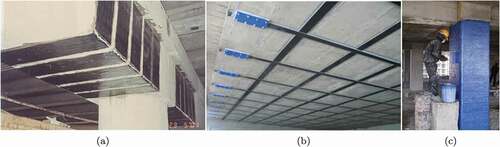
Figure 33. Different types of FRP deboning: (a) Interfacial debonding due to combined effects of shear and normal stress at the extremities of the FRP. (b) Debonding by concrete cover separation induced by a critical diagonal crack close to the FRP extremity. (c) Debonding at an intermediate flexural crack. (Figures adapted from[Citation339]).
![Figure 33. Different types of FRP deboning: (a) Interfacial debonding due to combined effects of shear and normal stress at the extremities of the FRP. (b) Debonding by concrete cover separation induced by a critical diagonal crack close to the FRP extremity. (c) Debonding at an intermediate flexural crack. (Figures adapted from[Citation339]).](/cms/asset/5db51778-a5f4-4507-a1bc-a61eb2999eab/gadh_a_1953479_f0033_b.gif)
Figure 34. Schematic representation test setups for characterizing the bond of FRP concrete systems: (a-b) EBR and (c-d) NSM.
Figure 35. Examples of single-shear test of bond of FRP: (a) EBR concrete, [Citation343] (b) EBR brick, [Citation345] (c) and (d) NSM timber.[Citation340,Citation346]
![Figure 35. Examples of single-shear test of bond of FRP: (a) EBR concrete, [Citation343] (b) EBR brick, [Citation345] (c) and (d) NSM timber.[Citation340,Citation346]](/cms/asset/e007cc8b-0639-4940-8a7f-e87cf3dc420a/gadh_a_1953479_f0035_oc.jpg)
Figure 36. Examples of double-shear test of bond of FRP: (a) EBR concrete, [Citation349] (b) EBR glass, [Citation350] (c) NSM concrete, [Citation351] (d) NSM concrete.[Citation352]
![Figure 36. Examples of double-shear test of bond of FRP: (a) EBR concrete, [Citation349] (b) EBR glass, [Citation350] (c) NSM concrete, [Citation351] (d) NSM concrete.[Citation352]](/cms/asset/a34a4948-64ca-46bf-a489-f8037c78a719/gadh_a_1953479_f0036_oc.jpg)
Figure 37. Examples of bending (flexural) beam set-up for: (a) EBR timber, [Citation353] (b) and (c) NSM timber.[Citation341,Citation353]
![Figure 37. Examples of bending (flexural) beam set-up for: (a) EBR timber, [Citation353] (b) and (c) NSM timber.[Citation341,Citation353]](/cms/asset/d022499b-00c1-4acf-a889-1121f27a0d76/gadh_a_1953479_f0037_oc.jpg)
Figure 38. Overview of influencing parameters related to adhesive bonding applications in automotive structures reproduced based on Quattro Daily.[Citation360]
![Figure 38. Overview of influencing parameters related to adhesive bonding applications in automotive structures reproduced based on Quattro Daily.[Citation360]](/cms/asset/62a5ab1f-0570-4dee-975a-d5047adcd2d3/gadh_a_1953479_f0038_oc.jpg)
Figure 39. Overview of adhesive bonds of panels/outer skin and impact resistance adhesive bonds of structural parts in modern body-in-white (© 3 M Company) reprinted from .[Citation376]
![Figure 39. Overview of adhesive bonds of panels/outer skin and impact resistance adhesive bonds of structural parts in modern body-in-white (© 3 M Company) reprinted from .[Citation376]](/cms/asset/3ac2ebc0-6a8b-4b1d-b9e1-0c450a7ba48d/gadh_a_1953479_f0039_oc.jpg)
Figure 40. Automotive related applications of T-shaped specimens for experimental testing with purely adhesive bonded flanges under crash loads.[Citation375,Citation377,Citation378]
![Figure 40. Automotive related applications of T-shaped specimens for experimental testing with purely adhesive bonded flanges under crash loads.[Citation375,Citation377,Citation378]](/cms/asset/19d718f0-7ebc-4646-a457-87fb5b1a28f5/gadh_a_1953479_f0040_oc.jpg)
Figure 41. White paint system (top left) and silver metallic paint system (top right) (1: base material, 2: zinc layer, 3: electro-coating, 4: filler, 5: basecoat, 6: topcoat) and performed test: (a) normal loading of butt-joints according to the DIN 15870, (b) Arcan tests for pure shearing, (c) tensile-shear of lap-joints and (d) T-peeling with higher load rate of 2 m/s according to Schiel et al. [Citation361].
![Figure 41. White paint system (top left) and silver metallic paint system (top right) (1: base material, 2: zinc layer, 3: electro-coating, 4: filler, 5: basecoat, 6: topcoat) and performed test: (a) normal loading of butt-joints according to the DIN 15870, (b) Arcan tests for pure shearing, (c) tensile-shear of lap-joints and (d) T-peeling with higher load rate of 2 m/s according to Schiel et al. [Citation361].](/cms/asset/ae73c03f-2e69-477e-accb-a3c1f9dd43d0/gadh_a_1953479_f0041_oc.jpg)
Figure 42. (a) Geometry of the CFRP single lap-joints and scheme of experimental setup (b) quasi-static and impact loads and (c) vibration according to Araújo et al.[Citation366]
![Figure 42. (a) Geometry of the CFRP single lap-joints and scheme of experimental setup (b) quasi-static and impact loads and (c) vibration according to Araújo et al.[Citation366]](/cms/asset/0c882677-2572-4b82-8365-8b7a50838e39/gadh_a_1953479_f0042_oc.jpg)
Figure 43. Proposed new design of CFRP node adhesively bonded to steel beams in bus structure according to Galvez et al.[Citation370]
![Figure 43. Proposed new design of CFRP node adhesively bonded to steel beams in bus structure according to Galvez et al.[Citation370]](/cms/asset/08b7eee0-a084-4cd6-8b64-00d9d5be8595/gadh_a_1953479_f0043_oc.jpg)
Figure 44. (a) Geometry of the CFRP/aluminium alloy mixed adhesively bonded butt joints and schematical experimental setup (b) under tensile and (c) under shearing according to Qin et al.[Citation364]
![Figure 44. (a) Geometry of the CFRP/aluminium alloy mixed adhesively bonded butt joints and schematical experimental setup (b) under tensile and (c) under shearing according to Qin et al.[Citation364]](/cms/asset/ebff3302-31c1-44d6-ad92-9d1642648b76/gadh_a_1953479_f0044_b.gif)
Acknowledgements
This publication is based on work from COST Action CA18120 (CERTBOND - “Reliable roadmap for certification of bonded primary structures” https://certbond.eu/), supported by COST (European Cooperation in Science and Technology - https://www.cost.eu/). The authors thank the EU-COST for facilitating the scientific networking between the involved Early Career Investigators and international experts.
Additional information
Funding
References
- Zuo, P.; Vassilopoulos, A. Review of Fatigue of Bulk Structural Adhesives and Thick Adhesive Joints. Int. Mater. Rev. 2020;66(5), 1–26.
- Fay, P.;. 1 - History of Adhesive Bonding; Adams, R., Ed; Adhesive Bonding, Woodhead Publishing Series in Welding and Other Joining Technologies, England: Woodhead Publishing, 2005; pp 3–22.
- Sheppard, S. E.; Sweet, S. S.; Scott, J. W. The Jelly Strength of Gelatins and Glues. J. Ind. Eng. Chem. 1920, 12(10), 1007–1011. DOI: 10.1021/ie50130a028.
- Skeist, I.;. Structural Adhesives: Chemistry and Technology. J. Polym. Sci. Part C. 1987, 25(3), 137. DOI: 10.1002/pol.1987.140250309.
- Duncan, B.;. Developments in Testing Adhesive Joints. In Advances in Structural Adhesive Bonding; UK: Elsevier, 2010; pp 389–436.
- Brockmann, W.; Geiß, P.; Klingen, J.; Schröder, B. Adhesive Bonding: Materials, Applications and Technology; WILEY - VCH verlag GmBH & co, KGaA, Weinheim, 2009.
- Ashcroft, I.; Hughes, D.; Shaw, S. Adhesive Bonding of Fibre Reinforced Polymer Composite Materials. Assembly Autom. 2000, 20(2), 150–161. DOI: 10.1108/01445150010321797.
- Sallam, H. Structural Joints in Polymeric Composite Materials, Prepared for Permanent Scientific Committee 56 for Structural and Construction Engineering 2004.
- Brunner, A.;. 8 - Fracture Mechanics Characterization of Polymer Composites for Aerospace Applications. In Polymer Composites in the Aerospace Industry; Irving, P., Soutis, C., Eds.; UK: Woodhead Publishing, 2015; pp 191–230.
- Banea, M. D.; da Silva, L. F. Adhesively Bonded Joints in Composite Materials: An Overview. Proc. Inst. Mech. Eng. Part L. 2009, 223(1), 1–18. DOI: 10.1243/14644207JMDA219.
- Hussey, R.; Wilson, J. Structural Adhesives: Directory and Databook; Chapman & Hall, London, UK: Springer Science & Business Media, 1996.
- Swayze, D. L. Adhesives-modern Tool of Fabrication, in: Pre-1964 SAE Technical Papers, SAE International, USA, 1946, pp. 412–417.
- Adams, R.; Wake, W. Structural Adhesive Joints in Engineering; England: Elsevier, 1986.
- Wahab, M. M. A.; Hilmy, I.; Ashcroft, I. A.; Crocombe, A. D. Evaluation of Fatigue Damage in Adhesive Bonding: Part 1: Bulk Adhesive. J. Adhes. Sci. Technol. 2010, 24(2), 305–324. DOI: 10.1163/016942409X12508517390798.
- Burst, N.; Adams, D. O.; Gascoigne, H. E. Investigating the Thin-film versus Bulk Material Properties of Structural Adhesives. J. Adhes. 2011, 87(1), 72–92. DOI: 10.1080/00218464.2011.538326.
- Hart-Smith, L.;. Adhesive Bonding of Aircraft Primary Structures. SAE Transactions. 1980, 89(4), 3718–3732.
- Nairn, J. A.;. Energy Release Rate Analysis for Adhesive and Laminate Double Cantilever Beam Specimens Emphasizing the Effect of Residual Stresses. Int. J. Adhes. Adhes. 2000, 20(1), 59–70. DOI: 10.1016/S0143-7496(99)00016-0.
- Kendall, K.;. Shrinkage and Peel Strength of Adhesive Joints. J. Phys. D: Appl. Phys. 1973, 6(15), 1782. DOI: 10.1088/0022-3727/6/15/304.
- Adams, R.; Coppendale, J.; Mallick, V.; Al-Hamdan, H. The Effect of Temperature on the Strength of Adhesive Joints. Int. J. Adhes. Adhes. 1992, 12(3), 185–190. DOI: 10.1016/0143-7496(92)90052-W.
- Allen, K.; Shanahan, M. The Creep Behaviour of Structural Adhesive Joints-i. J. Adhes. 1975, 7(3), 161–174. DOI: 10.1080/00218467508075048.
- Plausinis, D.; Spelt, J. Application of a New Constant G Load-jig to Creep Crack Growth in Adhesive Joints. Int. J. Adhes. Adhes. 1995, 15(4), 225–232. DOI: 10.1016/0143-7496(96)83703-1.
- Possart, W.; Jumel, J.; Budzik, M.; Guitard, J.; Shanahan, M. E. Experimental Study of Cohesive Strain Prior to Crack Initiation in Constant Force Single Cantilever Beam Test. J. Adhes. Sci. Technol. 2015, 29(9), 896–909. DOI: 10.1080/01694243.2015.1007554.
- Barra, G.; Vertuccio, L.; Vietri, U.; Naddeo, C.; Hadavinia, H.; Guadagno, L. Toughening of Epoxy Adhesives by Combined Interaction of Carbon Nanotubes and Silsesquioxanes. Materials. 2017, 10(10), 1131. DOI: 10.3390/ma10101131.
- Maheri, M.; Adams, R. Determination of Dynamic Shear Modulus of Structural Adhesives in Thick Adherend Shear Test Specimens. Int. J. Adhes. Adhes. 2002, 22(2), 119–127. DOI: 10.1016/S0143-7496(01)00043-4.
- Petković, G.; Vukoje, M.; Bota, J.; Pasanec Preprotić, S. Enhancement of Polyvinyl Acetate (Pvac) Adhesion Performance by Sio2 and Tio2 Nanoparticles. Coatings. 2019, 9(11), 707. DOI: 10.3390/coatings9110707.
- de Freitas, S. T.; Sinke, J. Test Method to Assess Interface Adhesion in Composite Bonding. Appl. Adhes. Sci. 2015, 3(9), 1–13. DOI: 10.1186/s40563-015-0033-5.
- Fernholz, K.;. Bonding of Polymer Matrix Composites. In Advances in Structural Adhesive Bonding; UK: Elsevier, 2010; pp 265–291.
- Winkler, E.;. The Theory of the Bending of Beams on an Elastic Foundation; Prague, 1867. pp 182.
- Volkersen, O.;. Die Nietkraftverteilung in Zugbeanspruchten Nietverbindungen Mit Konstanten Laschenquerschnitten. Luftfahrtfor Schung. 1938, 15, 41–47.
- Biot, M.;. Bending of an Infinite Beam on an Elastic Foundation. J. Appl. Math. Mech. 1922, 2(3), 165–184.
- Goland, M.;. The Stresses in Cemented Joints. J. Appl. Mech. 1944, 17, 66.
- Broughton, W.; Mera, R. Project PAJ3 Combined Cyclic Loading and Hostile Environments 1996-1999. Report No. 1, Review of Durability Test Methods and Standards for Assessing Long Term Performance of Adhesive Joints. 1997.
- Baldan, A.;. Adhesively-bonded Joints and Repairs in Metallic Alloys, Polymers and Composite Materials: Adhesives, Adhesion Theories and Surface Pretreatment. J. Mater. Sci. 2004, 39(1), 1–49. DOI: 10.1023/B:JMSC.0000007726.58758.e4.
- Habenicht, G.;. Applied Adhesive Bonding, A Practice Guide for Flawless Results. In ISBN, WILEY - VCH verlag GmBH & co, KGaA, Weinheim, 2009; pp 978.
- Banea, M.; Da Silva, L. F. Adhesively Bonded Joints in Composite Materials: An Overview. Proc. Inst. Mech. Eng. Part L. 2009, 223(1), 1–18. DOI: 10.1243/14644207JMDA219x.
- DIN EN 2243-1: Aerospace series-Non-metallic materials-Structural adhesives-Test Method Part 1: Single Lap Shear 2005.
- ASTM D1002-10 – Standard Test Method for Apparent Shear Strength of Single-lap-joint Adhesively Bonded Metal Specimens by Tension Loading (Metal-to-metal) 2010.
- ASTM D3163 – Standard Test Method for Determining Strength of Adhesively Bonded Rigid Plastic Lap-Shear Joints in Shear by Tension Loading 2019.
- ASTM D5868-01(2014) Standard Test Method for Lap Shear Adhesion for Fiber Reinforced Plastic (FRP) Bonding 2014.
- DVS 1618 (05/2017): Elastic Thick Layer Adhesives Used in Rail Vehicle Applications 2002.
- AITM 1-0019: Determination of Tensile Lap Shear Strength of Composite Joints 2017.
- Da Silva, L.; Campilho, R. Design of Adhesively-bonded Composite Joints. In Fatigue and Fracture of Adhesively-Bonded Composite Joints; UK: Woodhead Publishing Limited, 2015; pp 43–71.
- Budhe, S.; Banea, M.; De Barros, S.; Da Silva, L. An Updated Review of Adhesively Bonded Joints in Composite Materials. Int. J. Adhes. Adhes. 2017, 72, 30–42. DOI: 10.1016/j.ijadhadh.2016.10.010.
- Jeevi, G.; Nayak, S. K.; Abdul Kader, M. Review on Adhesive Joints and Their Application in Hybrid Composite Structures. J. Adhes. Sci. Technol. 2019, 33(14), 1497–1520. DOI: 10.1080/01694243.2018.1543528.
- Yang, C.; Huang, H.; Tomblin, J. S.; Oplinger, D. W. Evaluation and Adjustments for ASTM D 5656 Standard Test Method for Thick-adherend Metal Lap-shear Joints for Determination of the Stress-strain Behavior of Adhesives in Shear by Tension Loading. J. Test. Eval. 2001, 29(1), 36–43. DOI: 10.1520/JTE12389J.
- Kadioglu, F.; Vaughn, L.; Guild, F.; Adams, R. D. Use of the Thick Adherend Shear Test for Shear Stress-strain Measurements of Stiff and Flexible Adhesives. J. Adhes. 2002, 78(5), 355–381. DOI: 10.1080/00218460211818.
- Dilger, K.;. Selecting the Right Joint Design and Fabrication Techniques. In Advances in Structural Adhesive Bonding; UK: Woodhead Publishing Limited, 2010; pp 295–315.
- ISO 11003 – 2: Adhesives-determination of Shear Behaviour of Structural Adhesives-part 2: Tensile Test Method Using Thick Adherends 2011.
- ASTM D3983-98(2019): Standard Test Method for Measuring Strength and Shear Modulus of Nonrigid Adhesives by the Thick-Adherend Tensile-Lap Specimen 2019.
- Beber, V.; Schneider, B.; Brede, M. Influence of Temperature on the Fatigue Behaviour of a Toughened Epoxy Adhesive. J. Adhes. 2016, 92(7–9), 778–794. DOI: 10.1080/00218464.2015.1114927.
- De Barros, S.; Kenedi, P.; Ferreira, S.; Budhe, S.; Bernardino, A.; Souza, L. Influence of Mechanical Surface Treatment on Fatigue Life of Bonded Joints. J. Adhes. 2017, 93(8), 599–612. DOI: 10.1080/00218464.2015.1122531.
- Campilho, R. D.; De Moura, M.; Domingues, J. Modelling Single and Double-lap Repairs on Composite Materials. Compos. Sci. Technol. 2005, 65(13), 1948–1958. DOI: 10.1016/j.compscitech.2005.04.007.
- Da Silva, L. F.; Rodrigues, T.; Figueiredo, M.; De Moura, M.; Chousal, J. Effect of Adhesive Type and Thickness on the Lap Shear Strength. J. Adhes. 2006, 82(11), 1091–1115. DOI: 10.1080/00218460600948511.
- ASTM D3528–96 Standard Test Method for Strength Properties of Double Lap Shear Adhesive Joints by Tension Loading 2002.
- Kendall, K.;. Peel Adhesion of Solid Films-the Surface and Bulk Effects. J. Adhes. 1973, 5(3), 179–202. DOI: 10.1080/00218467308075019.
- Gent, A. N.; Hamed, G. R. Peel Mechanics. J. Adhes. 1975, 7(2), 91–95. DOI: 10.1080/00218467508075041.
- Adams, R. D.;. Adhesive Bonding: Science, Technology and Applications; UK: Woodhead Publishing Limited, 2005.
- ASTM D3167–10(2017) Standard Test Method for Strength Properties of Double Lap Shear Adhesive Joints by Tension Loading 2017.
- DIN EN 2243-2:2005: Aerospace Series - Non-metallic Materials - Structural Adhesives - Test Method - Part 2: Peel Metal-metal 2006.
- ASTM D1876: Standard Test Method for Peel Resistance of Adhesives (T-peel Test) 2015.
- ISO 11339:2010: Adhesives — T-peel Test for Flexible-to-flexible Bonded Assemblies 2010.
- Holtmannspötter, J.; Czarnecki, J.; Gudladt, H.-J. The Use of Power Ultrasound Energy to Support Interface Formation for Structural Adhesive Bonding. Int. J. Adhes. Adhes. 2010, 30(3), 130–138. DOI: 10.1016/j.ijadhadh.2009.10.002.
- de Freitas, S. T.; Sinke, J. Adhesion Properties of Bonded Composite-to-aluminium Joints Using Peel Tests. J. Adhes. 2014, 90(5–6), 511–525. DOI: 10.1080/00218464.2013.850424.
- de Freitas, S. T.; Sinke, J. Failure Analysis of Adhesively-bonded Skin-to-stiffener Joints: Metal–metal Vs. Composite–metal. Eng. Fail. Anal. 2015, 56, 2–13. DOI: 10.1016/j.engfailanal.2015.05.023.
- ASTM D1781–98 -test Method for Climbing Drum Peel for Adhesives 2012.
- EN 2243-3:2005: Aerospace Series - Non-metallic Materials - Structural Adhesives - Test Method - Part 3: Peeling Test Metal-honeycomb Core 2005.
- Griffith, A. The Phenomena of Rupture and Flow in Solids, Philosophical Transactions of the Royal Society of London. Series A, containing papers of a mathematical or physical character 221 1921. 582–593.
- Griffith, A.;. On the Griffith Energy Criterion for Brittle Fracture. Int. J. Solids Struct. 1967, 3(1), 1–22. DOI: 10.1016/0020-7683(67)90041-8.
- Goranson, U. Damage Tolerance-facts and Fiction, in: Proc. of the 17th Sympo. of the International Committee on Aeronautical Fatigue, Vol. 1, ICAF, 1993, Stockholm, Sweden, pp. 3–105.
- Nesterenko, G. Fatigue and Damage Tolerance of Aging Aircraft Structures, in: FAA-NASA Symposium on the Continued Airworthiness of Aircraft Structures, Atlanta, GA, Proceedings, Vol. 1, ICAF, 1996, Atlanta, USA, pp. 279.
- Tong, L.; Steven, G. P. Analysis and Design of Structural Bonded Joints; univ. of Sydney: New South Wales (AU), 1999.
- Alderliesten, R. C.;. Damage Tolerance of Bonded Aircraft Structures. Int. J. Fatigue. 2009, 31(6), 1024–1030. DOI: 10.1016/j.ijfatigue.2008.05.001.
- Nagy, K.; Körmendi, K. Use of Renewable Energy Sources in Light of the “New Energy Strategy for Europe 2011–2020”. Appl. Energy. 2012, 96, 393–399. DOI: 10.1016/j.apenergy.2012.02.066.
- van Kuik, G.; Peinke, J. Long-term Research Challenges in Wind Energy–a Research Agenda by the European Academy of Wind Energy; Cham, Switzerland: Springer, 2009.
- Leong, M.; Overgaard, L. C.; Thomsen, O. T.; Lund, E.; Daniel, I. M. Investigation of Failure Mechanisms in Gfrp Sandwich Structures with Face Sheet Wrinkle Defects Used for Wind Turbine Blades. Compos. Struct. 2012, 94(2), 768–778. DOI: 10.1016/j.compstruct.2011.09.012.
- Chen, X.; Zhao, W.; Zhao, X. L.; Xu, J. Z. Preliminary Failure Investigation of a 52.3m Glass/epoxy Composite Wind Turbine Blade. Eng. Fail. Anal. 2014, 44, 345–350. DOI: 10.1016/j.engfailanal.2014.05.024.
- McGugan, M.; Pereira, G.; Sørensen, B. F.; Toftegaard, H.; Branner, K. Damage Tolerance and Structural Monitoring for Wind Turbine Blades. Philos. Trans. Royal Soc. A. 2015, 373(2035), 20140077. DOI: 10.1098/rsta.2014.0077.
- Liu, Z.; Zhang, L. A Review of Failure Modes, Condition Monitoring and Fault Diagnosis Methods for Large-scale Wind Turbine Bearings. Measurement. 2020, 149, 107002. DOI: 10.1016/j.measurement.2019.107002.
- Groth, H.;. A Method to Predict Fracture in an Adhesively Bonded Joint. Int. J. Adhes. Adhes. 1985, 5(1), 19–22. DOI: 10.1016/0143-7496(85)90041-7.
- Abdel-Wahab, M. M.;. On the Use of Fracture Mechanics in Designing a Single Lap Adhesive Joint. J. Adhes. Sci. Technol. 2000, 14(6), 851–865. DOI: 10.1163/15685610051066758.
- Kafkalidis, M.; Thouless, M. The Effects of Geometry and Material Properties on the Fracture of Single Lap-shear Joints. Int. J. Solids Struct. 2002, 39(17), 4367–4383. DOI: 10.1016/S0020-7683(02)00344-X.
- Irwin, G.;. Linear Fracture Mechanics, Fracture Transition, and Fracture Control. Eng. Fract. Mech. 1968, 1(2), 241–257. DOI: 10.1016/0013-7944(68)90001-5.
- Williams, M.;. Stress Singularities Resulting from Various Boundary Conditions in Angular Corners of Plates in Extension. J. Appl. Mech. 1952, 19(4), 526–528. DOI: 10.1115/1.4010553.
- Zak, A. R.; Williams, M. L. Crack Point Stress Singularities at a Bi-material Interface; california Institute of Technology, USA, 1962.
- Hild, F.; Roux, S. Digital Image Correlation: From Displacement Measurement to Identification of Elastic Properties – A Review. Strain. 2006, 42(2), 69–80. DOI: 10.1111/j.1475-1305.2006.00258.x.
- Mokhtarishirazabad, M.; Lopez-Crespo, P.; Moreno, B.; Lopez-Moreno, A.; Zanganeh, M. Evaluation of Crack-tip Fields from DIC Data: A Parametric Study. Int. J. Fatigue. 2016, 89, 11–19. DOI: 10.1016/j.ijfatigue.2016.03.006.
- Rice, J.;. A Path Independent Integral and the Approximate Analysis of Strain Concentration by Notches and Cracks. J. Appl. Mech. 1968, 35(2), 379–386. DOI: 10.1115/1.3601206.
- Dugdale, D.;. Yielding of Steel Sheets Containing Slits. J. Mech. Phys. Solids. 1960, 8(2), 100–104. DOI: 10.1016/0022-5096(60)90013-2.
- Barenblatt, G. I.;. The Mathematical Theory of Equilibrium Cracks in Brittle Fracture. Adv. Appl. Mech. 1962, 7(1), 55–129.
- Zhu, X.-K.; Joyce, J. A. Review of Fracture Toughness (G, K, J, CTOD, CTOA) Testing and Standardization. Eng. Fract. Mech. 2012, 85, 1–46.
- Ernst, H. A.; Paris, P. C.; Landes, J. D. Estimations on J-integral and Tearing Modulus T from a Single Specimen Test Record. Fracture Mechanics. 1981, 476-502.
- Anthony, J.; Paris, P. C. Instantaneous Evaluation of J and C. Int. J. Fract. 1988, 38(1), R19–R20. DOI: 10.1007/BF00034281.
- Jumel, J.; Chauffaille, S.; Budzik, M. K.; Shanahan, M. E.; Guitard, J. Viscoelastic Foundation Analysis of Single Cantilevered Beam (Scb) Test under Stationary Loading. Eur. J. Mech.- A/Solids. 2013, 39, 170–179. DOI: 10.1016/j.euromechsol.2012.10.005.
- Bueckner, H. F.;. Novel Principle for the Computation of Stress Intensity Factors. Zeitschrift fuer Angewandte Mathematik and Mechanik. 1970, 50(9).
- Sih, G.;. 2012. Mechanics of Fracture Initiation and Propagation: Surface and Volume Energy Density Applied as Failure Criterion. Zeitschrift fuer Angewandte Mathematik and Mechanik 11.
- Cotterell, B.; Rice, J. Slightly Curved or Kinked Cracks. Int. J. Fract. 1980, 16(2), 155–169. DOI: 10.1007/BF00012619.
- Palaniswamy, K.; Knauss, W. G. Propagation of a Crack under General, In-plane Tension. Int. J. Fract.Mech. 1972, 8(1), 114–117. DOI: 10.1007/BF00185207.
- Davidson, B.; Krüger, R.; König, M. Three-dimensional Analysis of Center-delaminated Unidirectional and Multidirectional Single-leg Bending Specimens. Compos. Sci. Technol. 1995, 54(4), 385–394. DOI: 10.1016/0266-3538(95)00069-0.
- Møberg, A.; Budzik, M. K.; Jensen, H. M. Crack Front Morphology near the Free Edges in Double and Single Cantilever Beam Fracture Experiments. Eng. Fract. Mech. 2017, 175, 219–234. DOI: 10.1016/j.engfracmech.2017.01.030.
- Suo, Z.; Hutchinson, J. W. Interface Crack between Two Elastic Layers. Int. J. Fract. 1990, 43(1), 1–18. DOI: 10.1007/BF00018123.
- Jensen, H. M.; Hutchinson, J. W.; Kyung-Suk, K. Decohesion of a Cut Prestressed Film on a Substrate. Int. J. Solids Struct. 1990, 26(9), 1099–1114. DOI: 10.1016/0020-7683(90)90018-Q.
- Jensen, H.;. Three-dimensional Numerical Investigation of Brittle Bond Fracture. Int. J. Fract. 2002, 114(2), 153–165. DOI: 10.1023/A:1015066711279.
- Teixeira, J.; Campilho, R.; Da Silva, F. Numerical Assessment of the Double-cantilever Beam and Tapered Double-cantilever Beam Tests for the G Ic Determination of Adhesive Layers. J. Adhes. 2018, 94(11), 951–973. DOI: 10.1080/00218464.2017.1383905.
- ASTM D5528 –standard Test Method for Mode I Interlaminar Fracture Toughness of Unidirectional Fiber-Reinforced Polymer Matrix Composites 2007.
- Budhe, S.; Banea, M.; De Barros, S.; Da Silva, L. An Updated Review of Adhesively Bonded Joints in Composite Materials. Int. J. Adhes. Adhes. 2017, 72, 30–42. DOI: 10.1016/j.ijadhadh.2016.10.010x.
- Saseendran, V.; Berggreen, C.; Carlsson, L. A., Fracture Testing of Honeycomb Core Sandwich Composites Using the DCB-UBM Test, in: 20th International Conference on Composite Materials (ICCM20), ICCM20 Secretariat, 2015.
- Plausinis, D.; Spelt, J. Application of a New Constant G Load-jig to Creep Crack Growth in Adhesive Joints. Int. J. Adhes. Adhes. 1995, 15(4), 225–232. DOI: 10.1016/0143-7496(96)83703-1x.
- Sørensen, B. F.; Jørgensen, K.; Jacobsen, T. K.; Østergaard, R. C. Dcb-specimen Loaded with Uneven Bending Moments. Int. J. Fract. 2006, 141(1–2), 163–176. DOI: 10.1007/s10704-006-0071-x.
- Lundsgaard-Larsen, C.; Sørensen, B. F.; Berggreen, C.; Østergaard, R. C. A Modified Dcb Sandwich Specimen for Measuring Mixed-mode Cohesive Laws. Eng. Fract. Mech. 2008, 75(8), 2514–2530. DOI: 10.1016/j.engfracmech.2007.07.020.
- Lindgaard, E.; Bak, B. L. V. Experimental Characterization of Delamination in Off-axis GFRP Laminates during Mode I Loading. Compos. Struct. 2019, 220, 953–960. DOI: 10.1016/j.compstruct.2019.04.022.
- Bucci, R. J.; Paris, P. C.; Landes, J. D.; Rice, J. R. „J Integral Estimation Procedures,„ In Fracture Toughness: Part II, ed. H. Corten (West Conshohocken, PA: ASTM International, 1972), 40-69. 10.1520/STP38818S
- Rice, J.; Paris, P.; Merkle, J. Some Further Results of J-integral Analysis and Estimates. Progress in Flaw Growth and Fracture Toughness Testing; ASTM International, West Conshohocken, PA, 1973.
- Sørensen, B. F.; Jacobsen, T. K. Determination of Cohesive Laws by the J Integral Approach cohesive Models. Eng. Fract. Mech. 2003, 70(14), 1841–1858. DOI: 10.1016/S0013-7944(03)00127-9.
- Icardi, U.;. Higher-order Zig-zag Model for Analysis of Thick Composite Beams with Inclusion of Transverse Normal Stress and Sublaminates Approximations. Compos. B Eng. 2001, 32(4), 343–354. DOI: 10.1016/S1359-8368(01)00016-6.
- Kiss, B.; Szekrényes, A. Fracture and Mode Mixity Analysis of Shear Deformable Composite Beams. Arch. Appl. Mech. 2019, 89(12), 2485–2506. DOI: 10.1007/s00419-019-01591-4.
- Berry, J.;. Determination of Fracture Surface Energies by the Cleavage Technique. J. Appl. Phys. 1963, 34(1), 62–68. DOI: 10.1063/1.1729091.
- Blackman, B.; Kinloch, A.; Paraschi, M. The Determination of the Mode Ii Adhesive Fracture Resistance, Giic, of Structural Adhesive Joints: An Effective Crack Length Approach. Eng. Fract. Mech. 2005, 72(6), 877–897. DOI: 10.1016/j.engfracmech.2004.08.007.
- Bennati, S.; Fisicaro, P.; Valvo, P. S. An Enhanced Beam-theory Model of the Mixed-mode Bending (Mmb) Test—part Ii: Applications and Results. Meccanica. 2013, 48(2), 465–484. DOI: 10.1007/s11012-012-9682-7.
- Blackman, B.; Kinloch, A.; Paraschi, M. The Determination of the Mode Ii Adhesive Fracture Resistance, Giic, of Structural Adhesive Joints: An Effective Crack Length Approach Prospects in Fracture Papers from a Conference Held to Celebrate the 65th Birthday of Professor J.G. Williams, FRS, FREng Imperial College London, July 2003. Eng. Fract. Mech. 2005, 72(6), 877–897. DOI: 10.1016/j.engfracmech.2004.08.007x.
- de Morais, A. B.;. Analysis of the Fracture Process Zone and Effective Crack Length in the Adhesively Bonded End-notched Flexure Specimen. J. Adhes. 2019, 95(8), 770–795. DOI: 10.1080/00218464.2018.1440214.
- Sarrado, C.; Turon, A.; Costa, J.; Renart, J. An Experimental Analysis of the Fracture Behavior of Composite Bonded Joints in Terms of Cohesive Laws. Compos. Part A Appl. Sci. Manuf. 2016, 90, 234–242. DOI: 10.1016/j.compositesa.2016.07.004.
- Brunner, A.; Blackman, B.; Davies, P. A Status Report on Delamination Resistance Testing of Polymer–matrix Composites. Eng. Fract. Mech. 2008, 75(9), 2779–2794. DOI: 10.1016/j.engfracmech.2007.03.012.
- Brunner, A.;. Investigating the Performance of Adhesively-bonded Composite Joints: Standards, Test Protocols, and Experimental Design. In Fatigue and Fracture of Adhesively-Bonded Composite Joints; Cambridge, UK: Elsevier, 2015; pp 3–42.
- Crosley, P.; Ripling, E. A Thick Adherend, Instrumented Double-cantilever-beam Specimen for Measuring Debonding of Adhesive Joints. J. Test. Eval. 1991, 19(1), 24–28. DOI: 10.1520/JTE12525J.
- Budzik, M.; Jumel, J.; Shanahan, M. Process Zone in the Single Cantilever Beam under Transverse Loading – Part Ii: Experimental. Theor. Appl. Fract. Mech. 2011, 56(1), 13–21. DOI: 10.1016/j.tafmec.2011.09.005.
- Majumder, M.; Gangopadhyay, T. K.; Chakraborty, A. K.; Dasgupta, K.; Bhattacharya, D. Fibre Bragg Gratings in Structural Health Monitoring—present Status and Applications. Sens. Actuators A Phys. 2008, 147(1), 150–164. DOI: 10.1016/j.sna.2008.04.008.
- Canal, L. P.; Sarfaraz, R.; Violakis, G.; Botsis, J.; Michaud, V.; Limberger, H. G. Monitoring Strain Gradients in Adhesive Composite Joints by Embedded Fiber Bragg Grating Sensors. Compos. Struct. 2014, 112, 241–247. DOI: 10.1016/j.compstruct.2014.02.014.
- Manterola, J.; Aguirre, M.; Zurbitu, J.; Renart, J.; Turon, A.; Urresti, I. Using Acoustic Emissions (Ae) to Monitor Mode I Crack Growth in Bonded Joints. Eng. Fract. Mech. 2020, 224, 106778. DOI: 10.1016/j.engfracmech.2019.106778.
- Comer, A.; Katnam, K.; Stanley, W.; Young, T. Characterising the Behaviour of Composite Single Lap Bonded Joints Using Digital Image Correlation. Int. J. Adhes. Adhes. 2013, 40, 215–223. DOI: 10.1016/j.ijadhadh.2012.08.010.
- Kumar, R. V.; Bhat, M.; Murthy, C. Evaluation of Kissing Bond in Composite Adhesive Lap Joints Using Digital Image Correlation: Preliminary Studies. Int. J. Adhes. Adhes. 2013, 42, 60–68. DOI: 10.1016/j.ijadhadh.2013.01.004.
- Khudiakova, A.; Grasser, V.; Blumenthal, C.; Wolfahrt, M.; Pinter, G. Automated Monitoring of the Crack Propagation in Mode I Testing of Thermoplastic Composites by Means of Digital Image Correlation. Polym. Test. 2020, 82, 106304. DOI: 10.1016/j.polymertesting.2019.106304.
- Blackman, B.; Williams, J. Impact and High Rate Testing of Composites. In Mechanics of Composite Materials and Structures; Berlin, Heidelberg: Springer, 1999; pp 215–224.
- Blackman, B.; Kinloch, A.; Rodriguez Sanchez, F.; Teo, W.; Williams, J. The Fracture Behaviour of Structural Adhesives under High Rates of Testing Fracture of Polymers, Composites and Adhesives. Eng. Fract. Mech. 2009, 76(18), 2868–2889. DOI: 10.1016/j.engfracmech.2009.07.013.
- Blackman, B.; Kinloch, A.; Rodriguez-Sanchez, F.; Teo, W. The Fracture Behaviour of Adhesively-bonded Composite Joints: Effects of Rate of Test and Mode of Loading. Int. J. Solids Struct. 2012, 49(13), 1434–1452. DOI: 10.1016/j.ijsolstr.2012.02.022.
- Machado, J.; Marques, E.; Da Silva, L. F. Adhesives and Adhesive Joints under Impact Loadings: An Overview. J. Adhes. 2018, 94(6), 421–452. DOI: 10.1080/00218464.2017.1282349.
- Ravindran, S.; Sockalingam, S.; Kodagali, K.; Kidane, A.; Sutton, M. A.; Justusson, B.; Pang, J. Mode-i Behavior of Adhesively Bonded Composite Joints at High Loading Rates. Compos. Sci. Technol. 2020, 198, 108310. DOI: 10.1016/j.compscitech.2020.108310.
- Pirondi, A.; Nicoletto, G. Fatigue Crack Growth in Bonded Dcb Specimens Fracture and Damage Mechanics. Eng. Fract. Mech. 2004, 71(4–6), 859–871. DOI: 10.1016/S0013-7944(03)00046-8.
- Shahverdi, M.; Vassilopoulos, A. P.; Keller, T. Experimental Investigation of R-ratio Effects on Fatigue Crack Growth of Adhesively-bonded Pultruded GFRP DCB Joints under CA Loading. Compos. Part A Appl. Sci. Manuf. 2012, 43(10), 1689–1697. DOI: 10.1016/j.compositesa.2011.10.018.
- Budzik, M. K.; Jumel, J.; Salem, N. B.; Shanahan, M. E. R. Comparison of Cyclic and Monotonic Loading of a Double Cantilever Beam Adhesion Test. J. Adhes. 2014, 90(3), 252–267. DOI: 10.1080/00218464.2013.791620.
- Harris, J.; Fay, P. Fatigue Life Evaluation of Structural Adhesives for Automotive Applications. Int. J. Adhes. Adhes. 1992, 12(1), 9–18. DOI: 10.1016/0143-7496(92)90003-E.
- Khoramishad, H.; Crocombe, A.; Katnam, K.; Ashcroft, I. A Generalised Damage Model for Constant Amplitude Fatigue Loading of Adhesively Bonded Joints. Int. J. Adhes. Adhes. 2010, 30(6), 513–521. DOI: 10.1016/j.ijadhadh.2010.05.003.
- Vassilopoulos, A. P.;. Fatigue and Fracture of Adhesively-bonded Composite Joints; Cambridge, UK: Woodhead Publishing, 2014.
- Mai, Y.;. Cracking Stability in Tapered Dcb Test Pieces. Int. J. Fract. 1974, 10(2), 292–295. Cambridge, UK. DOI: 10.1007/BF00113939.
- Blackman, B.; Hadavinia, H.; Kinloch, A.; Paraschi, M.; Williams, J. The Calculation of Adhesive Fracture Energies in Mode I: Revisiting the Tapered Double Cantilever Beam (Tdcb) Test. Eng. Fract. Mech. 2003, 70(2), 233–248. DOI: 10.1016/S0013-7944(02)00031-0.
- Jethwa, J. K.; Kinloch, A. J. The Fatigue and Durability Behaviour of Automotive Adhesives. Part I: Fracture Mechanics Tests. J. Adhes. 1997, 61(1–4), 71–95. DOI: 10.1080/00218469708010517.
- Blackman, B.; Kinloch, A.; Paraschi, M.; Teo, W. Measuring the Mode I Adhesive Fracture Energy, Gic, of Structural Adhesive Joints: The Results of an International Round-robin. Int. J. Adhes. Adhes. 2003, 23(4), 293–305. DOI: 10.1016/S0143-7496(03)00047-2.
- BS7991: Determination of the Mode I Adhesive Fracture Energy GIC of Structure Adhesives Using the Double Cantilever Beam (DCB) and Tapered Double Cantilever Beam (TDCB) Specimens 2001.
- ISO 25217: 2009: Adhesives–Determination of the Mode 1 Adhesive Fracture Energy of Structural Adhesive Joints Using Double Cantilever Beam and Tapered Double Cantilever Beam Specimens 2009.
- Adams, R.; Cowap, J.; Farquharson, G.; Margary, G.; Vaughn, D. The Relative Merits of the Boeing Wedge Test and the Double Cantilever Beam Test for Assessing the Durability of Adhesively Bonded Joints, with Particular Reference to the Use of Fracture Mechanics Special Issue on Durability of Adhesive Joints. Int. J. Adhes. Adhes. 2009, 29(6), 609–620. DOI: 10.1016/j.ijadhadh.2009.02.010.
- Sargent, J.;. Durability Studies for Aerospace Applications Using Peel and Wedge Tests. Int. J. Adhes. Adhes. 2005, 25(3), 247–256. DOI: 10.1016/j.ijadhadh.2004.07.005.
- Cognard, J.;. Use of the Wedge Test to Estimate the Lifetime of an Adhesive Joint in an Aggressive Environment. Int. J. Adhes. Adhes. 1986, 6(4), 215–220. DOI: 10.1016/0143-7496(86)90008-4.
- ASTM D3762-03. Standard Test Method for Adhesive-Bonded Surface Durability of Aluminum (Wedge Test) 2010.
- Adams, D. O.; DeVries, K. L.; Child, C., Durability of Adhesively Bonded Joints for Aircraft Structures, FAA Jt Adv Mater Struct Cent Excell Tech Rev Meet 22 2012, USA.
- Budzik, M.; Jumel, J.; Shanahan, M. An in Situ Technique for the Assessment of Adhesive Properties of a Joint under Load. Int. J. Fract. 2011, 171(2), 111–124. DOI: 10.1007/s10704-011-9630-x.
- Manterola, J.; Zurbitu, J.; Renart, J.; Turon, A.; Urresti, I. Durability Study of Flexible Bonded Joints: The Effect of Sustained Loads in Mode I Fracture Tests. Polym. Test. 2020, 88, 106570. DOI: 10.1016/j.polymertesting.2020.106570.
- ISO 11343:2019: Adhesives — Determination of Dynamic Resistance to Cleavage of High-strength Adhesive Bonds under Impact Wedge Conditions — Wedge Impact Method 2019.
- Taylor, A. The Impact and Durability Performance of Adhesively-bonded Metal Joints, Ph.D. thesis, Imperial College of Science. 1997.
- Taylor, A.; Blackman, B.; Kinloch, A.; Wang, Y., Impact Testing of Adhesive Joints, MTS Adhesive Project 2 1996.
- Blackman, B.; Kinloch, A.; Taylor, A.; Wang., Y. The Impact Wedge-peel Performance of Structural Adhesives. J. Mater. Sci. 2000, 35(8), 1867–1884. DOI: 10.1023/A:1004793730352.
- Davies, P.; Sims, G.; Blackman, B.; Brunner, A.; Kageyama, K.; Hojo, M.; Tanaka, K.; Murri, G.; Rousseau, C.; Gieseke, B.; et al. Comparison of Test Configurations for Determination of Mode Ii Interlaminar Fracture Toughness Results from International Collaborative Test Programme. Plast., Rubber Compos. 1999, 28(9), 432–437. DOI: 10.1179/146580199101540600.
- Blackman, B.; Brunner, A.; Williams, J. Mode Ii Fracture Testing of Composites: A New Look at an Old Problem Fracture of Polymers, Composites and Adhesives. Eng. Fract. Mech. 2006, 73(16), 2443–2455. DOI: 10.1016/j.engfracmech.2006.05.022.
- Chaves, F. J. P.; Da Silva, L. F. M.; de Moura, M. F. S. F.; Dillard, D. A.; Esteves, V. H. C. Fracture Mechanics Tests in Adhesively Bonded Joints: A Literature Review. J. Adhes. 2014, 90(12), 955–992. DOI: 10.1080/00218464.2013.859075.
- de Moura, M.; Campilho, R.; Gonçalves, J. Pure Mode Ii Fracture Characterization of Composite Bonded Joints. Int. J. Solids Struct. 2009, 46(6), 1589–1595. DOI: 10.1016/j.ijsolstr.2008.12.001.
- Wang, H.; Vu-Khanh, T. Use of End-loaded-split (Els) Test to Study Stable Fracture Behaviour of Composites under Mode Ii Loading. Compos. Struct. 1996, 36(1–2), 71–79. DOI: 10.1016/S0263-8223(96)00066-9.
- Da Silva, L. F. M.; de Magalhães, F. A. C. R. G.; Chaves, F. J. P.; de Moura, M. F. S. F. Mode Ii Fracture Toughness of a Brittle and a Ductile Adhesive as a Function of the Adhesive Thickness. J. Adhes. 2010, 86(9), 891–905. DOI: 10.1080/00218464.2010.506155.
- Toolabi, M.; Blackman, B. Guidelines for Selecting the Dimensions of Adhesively Bonded End-loaded Split Joints: An Approach Based on Numerical Cohesive Zone Length. Eng. Fract. Mech. 2018, 203, 250–265. 8th ESIS TC4 International Conference- Fracture of Polymers, Composites and Adhesives DOI: 10.1016/j.engfracmech.2018.05.019.
- Jumel, J.; Budzik, M. Inverse End-loaded-split Test Analysis Effect of Small Scale Yielding. Theor. Appl. Fract. Mech. 2018, 96, 775–789. DOI: 10.1016/j.tafmec.2017.11.005.
- de Oliveira, B.; Campilho, R.; Silva, F.; Rocha, R. Comparison between the Enf and 4enf Fracture Characterization Tests to Evaluate Giic of Bonded Aluminium Joints. J. Adhes. 2018, 94(11), 910–931. DOI: 10.1080/00218464.2017.1387056.
- Alfredsson, K.;. On the Instantaneous Energy Release Rate of the End-notch Flexure Adhesive Joint Specimen. Int. J. Solids Struct. 2004, 41(16–17), 4787–4807. DOI: 10.1016/j.ijsolstr.2004.03.008.
- Alfredsson, K.; Stigh, U. Stability of Beam-like Fracture Mechanics Specimens. Eng. Fract. Mech. 2012, 89, 98–113. DOI: 10.1016/j.engfracmech.2012.04.027.
- Bing, Q.; Sun, C. Effect of Compressive Transverse Normal Stress on Mode Ii Fracture Toughness in Polymeric Composites. Int. J. Fract. 2007, 145(2), 89–97. DOI: 10.1007/s10704-007-9103-4.
- Budzik, M.; Jumel, J.; Ben Salem, N.; Shanahan, M. Instrumented End Notched Flexure – Crack Propagation and Process Zone Monitoring Part Ii: Data Reduction and Experimental. Int. J. Solids Struct. 2013, 50(2), 310–319. DOI: 10.1016/j.ijsolstr.2012.08.030.
- Davies, P.;. Influence of Enf Specimen Geometry and Friction on the Mode Ii Delamination Resistance of Carbon/peek. J. Thermoplast. Compos. Mater. 1997, 10(4), 353–361. DOI: 10.1177/089270579701000404.
- Qiao, P.; Wang, J.; Davalos, J. F. Analysis of Tapered Enf Specimen and Characterization of Bonded Interface Fracture under Mode-ii Loading. Int. J. Solids Struct. 2003, 40(8), 1865–1884. DOI: 10.1016/S0020-7683(03)00031-3.
- Pérez-Galmés, M.; Renart, J.; Sarrado, C.; Rodríguez-Bellido, A.; Costa, J. A Data Reduction Method Based on the J-integral to Obtain the Interlaminar Fracture Toughness in A Mode Ii End-loaded Split (Els) Test. Compos. Part A Appl. Sci. Manuf. 2016, 90, 670–677. DOI: 10.1016/j.compositesa.2016.08.020.
- Agarwall, B.; Giare, G. Fracture Toughness of Short Fibre Composites in Modes Ii and Iii. Eng. Fract. Mech. 1981, 15(1–2), 219–230. DOI: 10.1016/0013-7944(81)90119-3.
- Lee, S.;. An Edge Crack Torsion Method for Mode Iii Delamination Fracture Testing. Technol. Res. 1993, 15(3), 193–201.
- Pennas, D.; Cantwell, W. J.; Compston, P. The Influence of Loading Rate on the Mode Iii Fracture Properties of Adhesively Bonded Composites. J. Reinf. Plast. Compos. 2009, 28(16), 1999–2012. DOI: 10.1177/0731684408090716.
- Ripling, E. J.; Santner, J. S.; Crosley, P. B. Fracture Toughness of Composite Adherend Adhesive Joints under Mixed Mode I and Iii Loading. J. Mater. Sci. 1983, 18(8), 2274–2282. DOI: 10.1007/BF00541830.
- Donaldson, S.;. Mode Iii Interlaminar Fracture Characterization of Composite Materials. Compos. Sci. Technol. 1988, 32(3), 225–249. DOI: 10.1016/0266-3538(88)90022-X.
- Szekrenyes, A.;. Improved Analysis of the Modified Split-cantilever Beam for Mode-iii Fracture. Int. J. Mech. Sci. 2009, 51(9–10), 682–693. DOI: 10.1016/j.ijmecsci.2009.07.005.
- Cricri, G.; Perrella, M.; Sessa, S.; Valoroso, N. A Novel Fixture for Measuring Mode III Toughness of Bonded Assemblies. Eng. Fract. Mech. 2015, 138, 1–18. DOI: 10.1016/j.engfracmech.2015.03.019.
- Cricri, G.; Perrella, M. Investigation of Mode III Fracture Behaviour in Bonded Pultruded GFRP Composite Joints. Compos. B Eng. 2017, 112, 176–184. DOI: 10.1016/j.compositesb.2016.12.052.
- Pereira, A.; de Morais, A.; de Moura, M. Design and Analysis of a New Six-point Edge Crack Torsion (6ECT) Specimen for Mode III Interlaminar Fracture Characterisation. Compos. Part A Appl. Sci. Manuf. 2011, 42(2), 131–139. DOI: 10.1016/j.compositesa.2010.10.013.
- Jiang, Z.; Wan, S.; Zhong, Z.; Li, S.; Shen, K. Effect of Curved Delamination Front on mode-I Fracture Toughness of Adhesively Bonded Joints. Eng. Fract. Mech. 2015, 138, 73–91. DOI: 10.1016/j.engfracmech.2015.03.020.
- Liu, Y.; Lemanski, S.; Zhang, X. Parametric Study of Size, Curvature and Free Edge Effects on the Predicted Strength of Bonded Composite Joints. Compos. Struct. 2018, 202, 364–373. special issue dedicated to Ian Marshall DOI: 10.1016/j.compstruct.2018.02.017.
- Hutchinson, J.; Suo, Z. Mixed Mode Cracking in Layered Materials. In Advances in Applied Mechanics, Hutchinson, J. W., Wu, T. Y., Eds.; Cambridge, UK: Elsevier: 1991; Vol. 29, pp 63–191.
- Thouless, M. D.; Jensen, H. M. Elastic Fracture Mechanics of the Peel-test Geometry. J. Adhes. 1992, 38(3–4), 185–197. DOI: 10.1080/00218469208030454.
- Dillard, D. A.; Singh, H. K.; Pohlit, D. J.; Starbuck, J. M. Observations of Decreased Fracture Toughness for Mixed Mode Fracture Testing of Adhesively Bonded Joints. J. Adhes. Sci. Technol. 2009, 23(10–11), 1515–1530. DOI: 10.1163/156856109X452701.
- Ducept, F.; Gamby, D.; Davies, P. A Mixed-mode Failure Criterion Derived from Tests on Symmetric and Asymmetric Specimens. Compos. Sci. Technol. 1999, 59(4), 609–619. DOI: 10.1016/S0266-3538(98)00105-5.
- Datla, N.; Ulicny, J.; Carlson, B.; Papini, M.; Spelt, J. Mixed-mode Fatigue Behavior of Degraded Toughened Epoxy Adhesive Joints. Int. J. Adhes. Adhes. 2011, 31(2), 88–96. DOI: 10.1016/j.ijadhadh.2010.11.007.
- Radcliff, J.; Reeder, J. Sizing a Single Cantilever Beam Specimen for Characterizing Facesheet–core Debonding in Sandwich Structure. J. Compos. Mater. 2011, 45(25), 2669–2684. DOI: 10.1177/0021998311401116.
- Leseman, Z. C.; Carlson, S. P.; Mackin, T. J. Experimental Measurements of the Strain Energy Release Rate for Stiction-failed Microcantilevers Using a Single-cantilever Beam Peel Test. J. Microelectromech. Syst. 2007, 16(1), 38–43. DOI: 10.1109/JMEMS.2006.883570.
- Shin, D.; Lee, J.; Yoon, C.; Lee, G.; Hong, J.; Kim, N. Development of Single Cantilever Beam Method to Measure the Adhesion of Thin Film Adhesive on Silicon Chip. Eng. Fract. Mech. 2015, 133, 179–190. DOI: 10.1016/j.engfracmech.2014.10.004.
- Vanderkley, P. Mode I-mode Ii Delamination Fracture Toughness of a Unidirectional Graphite/epoxy Composite. Msc Dissertation, Ph.D. thesis, Texas AM University. 1981.
- Bennati, S.; Fisicaro, P.; Valvo, P. An Enhanced Beam-theory Model of the Mixed-mode Bending (Mmb) Test—part I: Literature Review and Mechanical Model. Meccanica. 2013, 48(2), 443–462. DOI: 10.1007/s11012-012-9686-3.
- Shahverdi, M.; Vassilopoulos, A. P.; Keller, T. Mixed-Mode I and II Fracture Behavior of Asymmetric Adhesively-bonded Pultruded Composite Joints. Eng. Fract. Mech. 2014, 115, 43–59. DOI: 10.1016/j.engfracmech.2013.11.014.
- Panettieri, E.; Leclerc, G.; Jumel, J.; Guitard, J. Mixed-mode Crack Propagation Tests of Composite Bonded Joints Using a Dual-actuator Load Frame – Constant and Variable Gii/gi Conditions. Eng. Fract. Mech. 2018, 202, 471–486. DOI: 10.1016/j.engfracmech.2018.09.015.
- Akhavan-Safar, A.; Ayatollahi, M.; Safaei, S.; Da Silva, L. Mixed Mode I/iii Fracture Behavior of Adhesive Joints. Int. J. Solids Struct. 2020, 199, 109–119. DOI: 10.1016/j.ijsolstr.2020.05.007.
- Loh, L.; Marzi, S. An Out-of-plane Loaded Double Cantilever Beam (ODCB) Test to Measure the Critical Energy Release Rate in Mode III of Adhesive Joints. Int. J. Adhes. Adhes. 2018, 83, 24–30. DOI: 10.1016/j.ijadhadh.2018.02.021.
- Loh, L.; Marzi, S. A Novel Experimental Methodology to Identify Fracture Envelopes and Cohesive Laws in Mixed-mode I and III. Eng. Fract. Mech. 2019, 214, 304–319. DOI: 10.1016/j.engfracmech.2019.03.011.
- Dhondt, G.; Chergui, A.; Buchholz, F.-G. Computational Fracture Analysis of Different Specimens regarding 3d and Mode Coupling Effects. Eng. Fract. Mech. 2001, 68(4), 383–401. DOI: 10.1016/S0013-7944(00)00104-1.
- Buchholz, F.-G.; Chergui, A.; Richard, H. Fracture Analyses and Experimental Results of Crack Growth under General Mixed Mode Loading Conditions Fracture and Damage Mechanics. Eng. Fract. Mech. 2004, 71(4–6), 455–468. DOI: 10.1016/S0013-7944(03)00015-8.
- Szekrényes, A.;. Delamination Fracture Analysis in the Gii–giii Plane Using Prestressed Transparent Composite Beams. Int. J. Solids Struct. 2007, 44(10), 3359–3378. DOI: 10.1016/j.ijsolstr.2006.09.029.
- de Morais, A.; Pereira, A. Mixed Mode II+III Interlaminar Fracture of Carbon/epoxy Laminates. Compos. Sci. Technol. 2008, 68(9), 2022–2027. DOI: 10.1016/j.compscitech.2008.02.023.
- Davidson, B. D.; Sediles, F. O. Mixed-mode I–II–III Delamination Toughness Determination via a Shear–torsion-bending Test. Compos. Part A Appl. Sci. Manuf. 2011, 42(6), 589–603. DOI: 10.1016/j.compositesa.2011.01.018.
- Floros, I.; Tserpes, K.; Löbel, T. Mode-I, mode-II and Mixed-mode I+II Fracture Behavior of Composite Bonded Joints: Experimental Characterization and Numerical Simulation. Compos. B Eng. 2015, 78, 459–468.
- Fernandes, R. L.; de Freitas, S. T.; Budzik, M. K.; Poulis, J. A.; Benedictus, R. From Thin to Extra-thick Adhesive Layer Thicknesses: Fracture of Bonded Joints under Mode I Loading Conditions. Eng. Fract. Mech. 2019, 218, 106607. DOI: 10.1016/j.engfracmech.2019.106607.
- Mishnaevsky, L.; Branner, K.; Petersen, H. N.; Beauson, J.; McGugan, M.; Sørensen, B. F. Materials for Wind Turbine Blades: An Overview. Materials. 2017, 10(11), 1285. DOI: 10.3390/ma10111285.
- Tada, H.; Paris, P. C.; Irwin, G. R. The Stress Analysis of Cracks. In Handbook, Del Research Corporation; 1973; Vol. 34, ASME, NY, USA.
- Orowan, E.;. Fracture and Strength of Solids. Rep. Prog. Phys. 1949, 12(1), 185. DOI: 10.1088/0034-4885/12/1/309.
- Lawn, B.;. Fracture of Brittle Solids; UK: Cambridge university press, 1993.
- Williams, J.;. Root Rotation and Plastic Work Effects in the Peel Test. J. Adhes. 1993, 41(1–4), 225–239. DOI: 10.1080/00218469308026564.
- Cotterell, B.; Hbaieb, K.; Williams, J.; Hadavinia, H.; Tropsa, V. The Root Rotation in Double Cantilever Beam and Peel Tests. Mech. Mater. 2006, 38(7), 571–584. DOI: 10.1016/j.mechmat.2005.11.001.
- Škec, L.; Alfano, G.; Jelenić, G. Enhanced Simple Beam Theory for Characterising Mode-i Fracture Resistance via a Double Cantilever Beam Test. Compos. B Eng. 2019, 167, 250–262. DOI: 10.1016/j.compositesb.2018.11.099.
- Kanninen, M.;. An Augmented Double Cantilever Beam Model for Studying Crack Propagation and Arrest. Int. J. Fract. 1973, 9(1), 83–92.
- Budzik, M.; Jumel, J.; Imielińska, K.; Shanahan, M. Effect of Adhesive Compliance in the Assessment of Soft Adhesives with the Wedge Test. J. Adhes. Sci. Technol. 2011, 25(1–3), 131–149. DOI: 10.1163/016942410X501133.
- Penado, F.;. A Closed Form Solution for the Energy Release Rate of the Double Cantilever Beam Specimen with an Adhesive Layer. J. Compos. Mater. 1993, 27(4), 383–407. DOI: 10.1177/002199839302700403.
- Kondo, K.;. Analysis of Double Cantilever Beam Specimen. Adv. Compos. Mater. 1995, 4(4), 355–366. DOI: 10.1163/156855195X00203.
- Mostovoy, S.; Ripling, E. Fracture Toughness of an Epoxy System. J. Appl. Polym. Sci. 1966, 10(9), 1351–1371. DOI: 10.1002/app.1966.070100913.
- Mostovoy, S.; Ripling, E. The Fracture Toughness and Stress Corrosion Cracking Characteristics of an Anhydride-hardened Epoxy Adhesive. J. Appl. Polym. Sci. 1971, 15(3), 641–659. DOI: 10.1002/app.1971.070150311.
- Kinloch, A.; Shaw, S. A Fracture Mechanics Approach to the Failure of Structural Joints, Developments in Adhesives- 2; Applied Science Publishers: (A 82-28576 13-39) London, 1981; Vol. 1981. pp 83–124
- Mall, S.; Ramamurthy, G. Effect of Bond Thickness on Fracture and Fatigue Strength of Adhesively Bonded Composite Joints. Int. J. Adhes. Adhes. 1989, 9(1), 33–37. DOI: 10.1016/0143-7496(89)90144-9.
- Kawashita, L.; Kinloch, A.; Moore, D.; Williams, J. The Influence of Bond Line Thickness and Peel Arm Thickness on Adhesive Fracture Toughness of Rubber Toughened Epoxy–aluminium Alloy Laminates. Int. J. Adhes. Adhes. 2008, 28(4–5), 199–210. DOI: 10.1016/j.ijadhadh.2007.05.005.
- Davies, P.; Sohier, L.; Cognard, J.-Y.; Bourmaud, A.; Choqueuse, D.; Rinnert, E.; Créac’hcadec, R. Influence of Adhesive Bond Line Thickness on Joint Strength. Int. J. Adhes. Adhes. 2009, 29(7), 724–736. DOI: 10.1016/j.ijadhadh.2009.03.002.
- Arenas, J. M.; Narbón, J. J.; Ala, C. Optimum Adhesive Thickness in Structural Adhesives Joints Using Statistical Techniques Based on Weibull Distribution. Int. J. Adhes. Adhes. 2010, 30(3), 160–165. DOI: 10.1016/j.ijadhadh.2009.12.003.
- Budzik, M.; Jumel, J.; Salem, N. B.; Shanahan, M. Instrumented End Notched Flexure–crack Propagation and Process Zone Monitoring Part Ii: Data Reduction and Experimental. Int. J. Solids Struct. 2013, 50(2), 310–319. DOI: 10.1016/j.ijsolstr.2012.08.030x.
- Ranade, S. R.; Guan, Y.; Ohanehi, D. C.; Dillard, J. G.; Batra, R. C.; Dillard, D. A. A Tapered Bondline Thickness Double Cantilever Beam (Dcb) Specimen Geometry for Combinatorial Fracture Studies of Adhesive Bonds. Int. J. Adhes. Adhes. 2014, 55, 155–160. DOI: 10.1016/j.ijadhadh.2014.08.006.
- Lee, M.; Wang, C. H.; Yeo, E. Effects of Adherend Thickness and Taper on Adhesive Bond Strength Measured by Portable Pull-off Tests. Int. J. Adhes. Adhes. 2013, 44, 259–268.
- Ji, G.; Ouyang, Z.; Li, G. On the Interfacial Constitutive Laws of Mixed Mode Fracture with Various Adhesive Thicknesses. Mech. Mater. 2012, 47, 24–32. DOI: 10.1016/j.mechmat.2012.01.002.
- Chen, B.; Dillard, D. A. Numerical Analysis of Directionally Unstable Crack Propagation in Adhesively Bonded Joints. Int. J. Solids Struct. 2001, 38(38–39), 6907–6924. DOI: 10.1016/S0020-7683(01)00006-3.
- Akisanya, A. R.; Meng, C. Initiation of Fracture at the Interface Corner of Bi-material Joints. J. Mech. Phys. Solids. 2003, 51(1), 27–46. DOI: 10.1016/S0022-5096(02)00076-5.
- Kotousov, A.; Lew, Y. T. Stress Singularities Resulting from Various Boundary Conditions in Angular Corners of Plates of Arbitrary Thickness in Extension. Int. J. Solids Struct. 2006, 43(17), 5100–5109.
- Reedy Jr., E.; Guess, T. Interface Corner Failure Analysis of Joint Strength: Effect of Adherend Stiffness. Int. J. Fract. 1997, 88(4), 305–314. DOI: 10.1023/A:1007436110715.
- Pardoen, T.; Ferracin, T.; Landis, C.; Delannay, F. Constraint Effects in Adhesive Joint Fracture. J. Mech. Phys. Solids. 2005, 53(9), 1951–1983. DOI: 10.1016/j.jmps.2005.04.009.
- Van Loock, F.; Thouless, M.; Fleck, N. Tensile Fracture of an Adhesive Joint: The Role of Crack Length and of Material Mismatch. J. Mech. Phys. Solids. 2019, 130, 330–348. DOI: 10.1016/j.jmps.2019.06.004.
- Fernandes, R. L.; de Freitas, S. T.; Budzik, M. K.; Poulis, J. A.; Benedictus, R. Role of Adherend Material on the Fracture of Bi-material Composite Bonded Joints. Compos. Struct. 2020, 252, 112643. DOI: 10.1016/j.compstruct.2020.112643.
- Lopes Fernandes, R.; Budzik, M. K.; Benedictus, R.; de Freitas, S. T. Multi-material Adhesive Joints with Thick Bond-lines: Crack Onset and Crack Deflection. Compos. Struct. 2021, 266, 113687. DOI: 10.1016/j.compstruct.2021.113687.
- Ala, C.; Arenas, J. M.; Suárez, J. C.; Ocana, R.; Narbón, J. J. Mode Ii Fracture Energy in the Adhesive Bonding of Dissimilar Substrates: Carbon Fibre Composite to Aluminium Joints. J. Adhes. Sci. Technol. 2013, 27(22), 2480–2494. DOI: 10.1080/01694243.2013.787516.
- Wang, W.; Lopes Fernandes, R.; De Freitas, S. T.; Zarouchas, D.; Benedictus, R. How Pure Mode I Can Be Obtained in Bi-material Bonded DCB Joints: A Longitudinal Strain-based Criterion. Compos. B Eng. 2018, 153, 137–148. DOI: 10.1016/j.compositesb.2018.07.033.
- Dempsey, J.; Sinclair, G. On the Singular Behavior at the Vertex of a Bi-material Wedge. J. Elast. 1981, 11(3), 317–327. DOI: 10.1007/BF00041942.
- Akisanya, A. R.; Fleck, N. A. Brittle Fracture of Adhesive Joints. Int. J. Fract. 1992, 58(2), 93–114. DOI: 10.1007/BF00019971.
- Arouche, M. M.; Wang, W.; de Freitas, S. T.; De Barros, S. Strain-based Methodology for Mixed-mode I+ii Fracture: A New Partitioning Method for Bi-material Adhesively Bonded Joints. J. Adhes. 2019, 95(5–7), 385–404. DOI: 10.1080/00218464.2019.1565756.
- Guo, R.; Morishima, S. Numerical Analysis and Experiment of Composite Sandwich T-joints Subjected to Pulling Load. Compos. Struct. 2011, 94(1), 229–238. DOI: 10.1016/j.compstruct.2011.06.022.
- de Freitas, S. T.; Sinke, J. Failure Analysis of Adhesively-bonded Skin-to-stiffener Joints: Metal–metal Vs. Composite–metal. 2015, 56, 2–13. the Sixth International Conference on Engineering Failure Analysis DOI: 10.1016/j.engfailanal.2015.05.023x.
- Carneiro, M. A. S.; Campilho, R. D. S. G. Analysis of Adhesively-bonded T-joints by Experimentation and Cohesive Zone Models. J. Adhes. Sci. Technol. 2017, 31(18), 1998–2014. DOI: 10.1080/01694243.2017.1291320.
- Domingues, N.; Campilho, R.; Carbas, R.; Da Silva, L. Experimental and Numerical Failure Analysis of Aluminium/composite Single-l Joints. Int. J. Adhes. Adhes. 2016, 64, 86–96. DOI: 10.1016/j.ijadhadh.2015.10.011.
- Greenhalgh, E.; Garcia, M. H. Fracture Mechanisms and Failure Processes at Stiffener Run-outs in Polymer Matrix Composite Stiffened Elements. Compos. Part A Appl. Sci. Manuf. 2004, 35(12), 1447–1458. DOI: 10.1016/j.compositesa.2004.05.006.
- Reinoso, J.; Blázquez, A.; Estefani, A.; París, F.; Cañas, J. A Composite Runout Specimen Subjected to Tension–compression Loading Conditions: Experimental and Global–local Finite Element Analysis. Compos. Struct. 2013, 101, 274–289. DOI: 10.1016/j.compstruct.2012.12.056.
- Reinoso, J.; Blázquez, A.; Távara, L.; París, F.; Arellano, C. Damage Tolerance of Composite Runout Panels under Tensile Loading. Compos. B Eng. 2016, 96, 79–93. DOI: 10.1016/j.compositesb.2016.03.083.
- Cardoso, J. V.; Gamboa, P. V.; Silva, A. P. Effect of Surface Pre-treatment on the Behaviour of Adhesively-bonded CFRP T-joints. Eng. Fail. Anal. 2019, 104, 1188–1202. DOI: 10.1016/j.engfailanal.2019.05.043.
- Greenhalgh, E.; Meeks, C.; Clarke, A.; Thatcher, J. The Effect of Defects on the Performance of Post-buckled Cfrp Stringer-stiffened Panels. Compos. Part A Appl. Sci. Manuf. 2003, 34(7), 623–633. DOI: 10.1016/S1359-835X(03)00098-8.
- Meeks, C.; Greenhalgh, E.; Falzon, B. G. Stiffener Debonding Mechanisms in Post-buckled Cfrp Aerospace Panels. Compos. Part A Appl. Sci. Manuf. 2005, 36(7), 934–946. DOI: 10.1016/j.compositesa.2004.12.003.
- Matthews, F.; Kilty, P.; Godwin, E. A Review of the Strength of Joints in Fibre-reinforced Plastics. Part 2. Adhesively Bonded Joints. Composites. 1982, 13(1), 29–37. DOI: 10.1016/0010-4361(82)90168-9.
- Wingfield, J.;. Treatment of Composite Surfaces for Adhesive Bonding. Int. J. Adhes. Adhes. 1993, 13(3), 151–156. DOI: 10.1016/0143-7496(93)90036-9.
- Reis, P.; Ferreira, J.; Richardson, M. Effect of the Surface Preparation on PP Reinforced Glass Fiber Adhesive Lap Joints Strength. J. Thermoplast. Compos. Mater. 2012, 25(1), 3–13. DOI: 10.1177/0892705711408161.
- Tornow, C.; Schlag, M.; Lima, L. C. M.; Stübing, D.; Hoffmann, M.; Noeske, P.-L. M.; Brune, K.; Dieckhoff, S. Quality Assurance Concepts for Adhesive Bonding of Composite Aircraft Structures–characterisation of Adherent Surfaces by Extended Ndt. J. Adhes. Sci. Technol. 2015, 29(21), 2281–2294. DOI: 10.1080/01694243.2015.1055062.
- Molitor, P.; Barron, V.; Young, T. Surface Treatment of Titanium for Adhesive Bonding to Polymer Composites: A Review. Int. J. Adhes. Adhes. 2001, 21(2), 129–136. DOI: 10.1016/S0143-7496(00)00044-0.
- Marques, A. C.; Mocanu, A.; Tomić, N. Z.; Balos, S.; Stammen, E.; Lundevall, A.; Abrahami, S. T.; Günther, R.; de Kok, J. M.; de Freitas, S. T. Review on Adhesives and Surface Treatments for Structural Applications: Recent Developments on Sustainability and Implementation for Metal and Composite Substrates. Materials. 2020, 13(24), 5590. DOI: 10.3390/ma13245590.
- Critchlow, G.; Brewis, D. Review of Surface Pretreatments for Aluminium Alloys. Int. J. Adhes. Adhes. 1996, 16(4), 255–275. DOI: 10.1016/S0143-7496(96)00014-0.
- Dieckhoff, S.; Standfuß, J.; Pap, J.-S.; Klotzbach, A.; Zimmermann, F.; Burchardt, M.; Regula, C.; Wilken, R.; Apmann, H.; Fortkamp, K.; et al. New Concepts for Cutting, Surface Treatment and Forming of Aluminium Sheets Used for Fibre-metal Laminate Manufacturing. CEAS Aeronaut. J. 2019, 10(2), 419–429.
- Falzon, B.; Stevens, K.; Davies, G. Postbuckling Behaviour of a Blade-stiffened Composite Panel Loaded in Uniaxial Compression. Compos. Part A Appl. Sci. Manuf. 2000, 31(5), 459–468. DOI: 10.1016/S1359-835X(99)00085-8.
- Zhan, X.; Gu, C.; Wu, H.; Liu, H.; Chen, J.; Chen, J.; Wei, Y. Experimental and Numerical Analysis on the Strength of 2060 Al–li Alloy Adhesively Bonded T Joints. Int. J. Adhes. Adhes. 2016, 65, 79–87. DOI: 10.1016/j.ijadhadh.2015.11.010.
- Krueger, R.; Minguet, P. J. Analysis of Composite Skin–stiffener Debond Specimens Using a Shell/3d Modeling Technique. Compos. Struct. 2007, 81(1), 41–59. DOI: 10.1016/j.compstruct.2006.05.006.
- Reinoso, J.; Blázquez, A.; Estefani, A.; París, F.; Cañas, J.; Arévalo, E.; Cruz, F. Experimental and Three-dimensional Global-local Finite Element Analysis of a Composite Component Including Degradation Process at the Interfaces. Compos. B Eng. 2012, 43(4), 1929–1942. DOI: 10.1016/j.compositesb.2012.02.010.
- Akpinar, S.; Aydin, M. D.; Özel, A. A Study on 3-d Stress Distributions in the Bi-adhesively Bonded T-joints. Appl. Math. Modell. 2013, 37(24), 10220–10230. DOI: 10.1016/j.apm.2013.06.008.
- de Freitas, S. T.; Sinke, J. Failure Analysis of Adhesively-bonded Metal-skin-to-composite-stiffener: Effect of Temperature and Cyclic Loading. Compos. Struct. 2017, 166, 27–37. DOI: 10.1016/j.compstruct.2017.01.027.
- Kolanu, N. R.; Raju, G.; Ramji, M. Experimental and Numerical Studies on the Buckling and Post-buckling Behavior of Single Blade-stiffened Cfrp Panels. Compos. Struct. 2018, 196, 135–154. DOI: 10.1016/j.compstruct.2018.05.015.
- Xará, J.; Campilho, R. Strength Estimation of Hybrid Single-l Bonded Joints by the Extended Finite Element Method. Compos. Struct. 2018, 183, 397–406. in honor of Prof. Y. Narita DOI: 10.1016/j.compstruct.2017.04.009.
- Vijayaraju, K.; Mangalgiri, P.; Dattaguru, B. Experimental Study of Failure and Failure Progression in T-stiffened Skins. Compos. Struct. 2004, 64(2), 227–234. DOI: 10.1016/j.compstruct.2003.08.007.
- Li, J. Pull-off Tests and Analysis of Composite Skin and Frame T-joint, in: 17th Annu. Tech. Conf. Am. Soc. Compos., 2002, USA.
- Sargent, J.; Wilson, Q. Prediction of “Zed” Section Stringer Pull-off Loads. Int. J. Adhes. Adhes. 2003, 23(3), 189–198. DOI: 10.1016/S0143-7496(03)00011-3.
- Zhang, K.; Li, L.; Duan, Y.; Li, Y. Experimental and Theoretical Stress Analysis for an Interface Stress Model of Single-l Adhesive Joints between Cfrp and Aluminum Components. Int. J. Adhes. Adhes. 2014, 50, 37–44. DOI: 10.1016/j.ijadhadh.2013.12.021.
- Justo, J.; Reinoso, J.; Blázquez, A. Experimental Failure Investigation of Pull-off Tests of Single T-stiffened Composite Specimens. Compos. Struct. 2017, 177, 13–27. DOI: 10.1016/j.compstruct.2017.04.070.
- Feih, S.; Shercliff, H. Composite Failure Prediction of Single-l Joint Structures under Bending. Compos. Part A Appl. Sci. Manuf. 2005, 36(3), 381–395. DOI: 10.1016/j.compositesa.2004.06.021.
- Feih, S.; Shercliff, H. Adhesive and Composite Failure Prediction of Single-l Joint Structures under Tensile Loading. Int. J. Adhes. Adhes. 2005, 25(1), 47–59. DOI: 10.1016/j.ijadhadh.2004.02.005.
- Zimmermann, R.; Klein, H.; Kling, A. Buckling and Postbuckling of Stringer Stiffened Fibre Composite Curved Panels – Tests and Computations. international Conference on Buckling and Postbuckling Behavior of Composite Laminated Shell Structures. 2006, 73, 150–161.
- Reinoso, J.; Blázquez, A.; París, F.; Cañas, J.; Meléndez, J. Postbuckling Behaviour of a Pressurized Stiffened Composite Panel – Part I: Experimental Study. Compos. Struct. 2012, 94(5), 1533–1543. DOI: 10.1016/j.compstruct.2011.12.014.
- Psarras, S.; Pinho, S.; Falzon, B. Design of Composite Stiffener Run-outs for Damage Tolerance Computational Mechanics and Design. Finite Ele. Anal. Des. 2011, 47(8), 949–954. DOI: 10.1016/j.finel.2011.03.011.
- Demir Aydin, M.; Akpinar, S. The Strength of the Adhesively Bonded T-joints with Embedded Supports. Int. J. Adhes. Adhes. 2014, 50, 142–150. DOI: 10.1016/j.ijadhadh.2013.12.028.
- Da Silva, L. F.; Adams, R. The Strength of Adhesively Bonded T-joints. Int. J. Adhes. Adhes. 2002, 22(4), 311–315. DOI: 10.1016/S0143-7496(02)00009-X.
- Zarouchas, D.; Nijssen, R. Mechanical Behaviour of Thick Structural Adhesives in Wind Turbine Blades under Multi-axial Loading. J. Adhes. Sci. Technol. 2016, 30(13), 1413–1429. DOI: 10.1080/01694243.2016.1146392.
- Antoniou, A.; Vespermann, M.; Sayer, F.; Krimmer, A., Life Prediction Analysis of Thick Adhesive Bond Lines under Variable Amplitude Fatigue Loading, in: Proc. 18th European Conference on Composite Materials, ECCM18, 2018, Athens, Greece.
- Sayer, F.; Antoniou, A.; Van Wingerde, A. Investigation of Structural Bond Lines in Wind Turbine Blades by Sub-component Tests. Int. J. Adhes. Adhes. 2012, 37, 129–135. special Issue on Joint Design 3 DOI: 10.1016/j.ijadhadh.2012.01.021.
- Jorgensen, J. B.;. Adhesive Joints in Wind Blades; Denmark: Denmark Technical University, 2017.
- Veers, P. S.; Ashwill, T. D.; Sutherland, H. J.; Laird, D. L.; Lobitz, D. W.; Griffin, D. A.; Mandell, J. F.; Musial, W. D.; Jackson, K.; Zuteck, M. et al. Trends in the Design, Manufacture and Evaluation of Wind Turbine Blades. Wind Energy. 2003, 6(3), 245–259. DOI: 10.1002/we.90
- Bidaud, P. Analysis of the Cyclic Behavior of an Adhesive in an Assembly for Offshore Windmills Applications, Université Bretagne Occidentale 2014.
- Crawford, C. A. The Path from Functional to Detailed Design of a Coning Rotor Wind Turbine Concept, Proceedings of the Canadian Engineering Education Association (CEEA), Canada, 2007.
- Branner, K.; Berring, P. 2014. Methods for Testing of Geometrical Down-scaled Rotor Blades. DTU Wind Energy E 0069.
- Philippidis, T.; Vassilopoulos, A.; Katopis, K.; Voutsinas, S. Thin/probeam: A Software for Fatigue Design and Analysis of Composite Rotor Blades. Wind Eng. 1996, 20(5), 349–362.
- Swolfs, Y.;. Perspective for Fibre-hybrid Composites in Wind Energy Applications. Materials. 2017, 10(11), 1281. DOI: 10.3390/ma10111281.
- Ribeiro, F.; Sena-Cruz, J.; Vassilopoulos, A. P. Tension-tension Fatigue Behavior of Hybrid Glass/carbon and Carbon/carbon Composites. Int. J. Fatigue 2021, 146, 106143. in press. DOI: 10.1016/j.ijfatigue.2021.106143.
- Movahedi-Rad, A.-V.; Keller, T.; Vassilopoulos, A. P. Fatigue Damage in Angle-ply Gfrp Laminates under Tension-tension Fatigue. Int. J. Fatigue. 2018, 109, 60–69. DOI: 10.1016/j.ijfatigue.2017.12.015.
- Movahedi-Rad, A.-V.; Keller, T.; Vassilopoulos, A. P. Interrupted Tension-tension Fatigue Behavior of Angle-ply Gfrp Composite Laminates. Int. J. Fatigue. 2018, 113, 377–388. DOI: 10.1016/j.ijfatigue.2018.05.001.
- Philippidis, T. P.; Vassilopoulos, A. P. Life Prediction Methodology for GFRP Laminates under Spectrum Loading. Compos. Part A Appl. Sci. Manuf. 2004, 35(6), 657–666. DOI: 10.1016/j.compositesa.2004.02.009.
- Mandell, J.; Samborsky, D., Snl/msu/doe Composite Material Fatigue Database, version 29.0, 2009.
- Savvilotidou, M.; Keller, T.; Vassilopoulos, A. P. Fatigue Performance of a Cold-curing Structural Epoxy Adhesive Subjected to Moist Environments. Int. J. Fatigue. 2017, 103, 405–414. DOI: 10.1016/j.ijfatigue.2017.06.022.
- Zhang, Y.; Vassilopoulos, A. P.; Keller, T. Fracture of Adhesively-bonded Pultruded GFRP Joints under Constant Amplitude Fatigue Loading. Int. J. Fatigue. 2010, 32(7), 979–987. DOI: 10.1016/j.ijfatigue.2009.11.004.
- Sarfaraz, R.; Vassilopoulos, A. P.; Keller, T. Experimental Investigation of the Fatigue Behavior of Adhesively-bonded Pultruded GFRP Joints under Different Load Ratios. Int. J. Fatigue. 2011, 33(11), 1451–1460. DOI: 10.1016/j.ijfatigue.2011.05.012.
- Shahverdi, M.; Vassilopoulos, A. P.; Keller, T. A Phenomenological Analysis of Mode I Fracture of Adhesively-bonded Pultruded GFRP Joints. Eng. Fract. Mech. 2011, 78(10), 2161–2173. DOI: 10.1016/j.engfracmech.2011.04.007.
- Sarfaraz, R.; Vassilopoulos, A. P.; Keller, T. Experimental Investigation and Modeling of Mean Load Effect on Fatigue Behavior of Adhesively-bonded Pultruded GFRP Joints. Int. J. Fatigue. 2012, 44(8), 245–252. DOI: 10.1016/j.ijfatigue.2012.04.021.
- Shahverdi, M.; Vassilopoulos, A. P.; Keller, T. A Total Fatigue Life Model for the Prediction of the R-ratio Effects on Fatigue Crack Growth of Adhesively-bonded Pultruded GFRP DCB Joints. Compos. Part A Appl. Sci. Manuf. 2012, 43(10), 1783–1790. DOI: 10.1016/j.compositesa.2012.05.004.
- Sarfaraz, R.; Vassilopoulos, A. P.; Keller, T. Variable Amplitude Fatigue of Adhesively-bonded Pultruded GFRP Joints. Int. J. Fatigue. 2013, 55, 22–32. DOI: 10.1016/j.ijfatigue.2013.04.024.
- Zhang, Y.; Vassilopoulos, A. P.; Keller, T. Environmental Effects on Fatigue Behavior of Adhesively-bonded Pultruded Structural Joints. Compos. Sci. Technol. 2009, 69(7–8), 1022–1028. DOI: 10.1016/j.compscitech.2009.01.024.
- DNVGL-ST-0376, Rotor Blades for Wind Turbines 2015.
- Kim, S.-W.; Kang, W.-R.; Jeong, M.-S.; Leel, I.; Kwon, I.-B. Deflection Estimation of a Wind Turbine Blade Using Fbg Sensors Embedded in the Blade Bonding Line. Smart Mater. Struct. 2013, 22(12), 125004. DOI: 10.1088/0964-1726/22/12/125004.
- Fernandez, G.; Vandepitte, D.; Usabiaga, H.; Debruyne, S. Static and Cyclic Strength Properties of Brittle Adhesives with Porosity. 2017, 7, 291–298. 3rd International Symposium on Fatigue Design and Material Defects, FDMD 2017.
- Griffin, D. A.; Malkin, M. C., Lessons Learned from Recent Blade Failures: Primary Causes and Risk-reducing Technologies, in: 49th AIAA Aerospace Sciences Meeting including the New Horizons Forum and Aerospace Exposition, Orlando, Florida, USA, 2017, p. 259.
- Wetzel, K. K. Defect-tolerant Structural Design of Wind Turbine Blades, In: 50th AIAA/ASME/ASCE/AHS/ASC Structures, Structural Dynamics, and Materials Conference, Palm Springs, California, USA, 2009, p. 2409.
- Zarouchas, D.; Nijssen, R. Mechanical Behaviour of Thick Structural Adhesives in Wind Turbine Blades under Multi-axial Loading. J. Adhes. Sci. Technol. 2016, 30(13), 1413–1429. DOI: 10.1080/01694243.2016.1146392x.
- Burst, N.; Adams, D. O.; Gascoigne, H. E. Investigating the Thin-film versus Bulk Material Properties of Structural Adhesives. J. Adhes. 2011, 87(1), 72–92. DOI: 10.1080/00218464.2011.538326x.
- Lees, D.; Hutchinson, A. Mechanical Characteristics of Some Cold-cured Structural Adhesives. Int. J. Adhes. Adhes. 1992, 12(3), 197–205. DOI: 10.1016/0143-7496(92)90054-Y.
- McGugan, M.; Pereira, G.; Sørensen, B.; Toftegaard, H.; Branner, K. Damage Tolerance and Structural Monitoring for Wind Turbine Blades. Philos Trans A Math Phys Eng Sci. 2014, 373(2035).
- Adams, R.; Peppiatt, N. Stress Analysis of Adhesive-bonded Lap Joints. J. Strain Anal. Eng. Des. 1974, 9(3), 185-196.
- Park, J.-H.; Choi, J.-H.; Kweon, J.-H. Evaluating the Strengths of Thick Aluminum-to-aluminum Joints with Different Adhesive Lengths and Thicknesses fifteenth International Conference on Composite Structures. 2010, 92, 2226–2235.
- Grant, L.; Adams, R.; Da Silva, L. F. Experimental and Numerical Analysis of Single-lap Joints for the Automotive Industry. Int. J. Adhes. Adhes. 2009, 29(4), 405–413. DOI: 10.1016/j.ijadhadh.2008.09.001.
- Rosemeier, M.; Antoniou, A.; Lester, C. Sub-components of Wind Turbine Blades: Proof of a Novel Trailing Edge Testing Concept. In Mechanics of Composite, Hybrid and Multifunctional Materials, Berlin, Heidelberg: Springer: 2019; Vol. 5, pp 267–274.
- Sharp, K.; Bogdanovich, A.; Boyle, R.; Brown, J.; Mungalov, D. Wind Blade Joints Based on Non-crimp 3d Orthogonal Woven Pi Shaped Preforms. Compos. Part A Appl. Sci. Manuf. 2013, 49, 9–17. DOI: 10.1016/j.compositesa.2013.01.012.
- Zarouchas, D.; Makris, A.; Sayer, F.; Van Hemelrijck, D.; Van Wingerde, A. Investigations on the Mechanical Behavior of a Wind Rotor Blade Subcomponent. Compos. B Eng. 2012, 43(2), 647–654. DOI: 10.1016/j.compositesb.2011.10.009.
- Broughton, W. Review of Durability Test Methods and Standards for Assessing Long Term Performance of Adhesive Joints: Report No. 1, Nat. Phys. Lab, 1997.
- Sears, A. T.; Samborsky, D. D.; Agastra, J. P.; Mandell., F., Fatigue Results and Analysis for Thick Adhesive Notched Lap Shear Test, in: 51st AIAA/ASME/ASCE/AHS/ASC Structures, Structural Dynamics, and Materials Conference, Orlando, Florida, USA, 2010, pp. 12–15.
- Samborsky, D. D.; Mandell, J.; Sears, A.; Kils., O., Static and Fatigue Testing of Thick Adhesive Joints for Wind Turbine Blades, in: Proc. 47th AIAA Aerospace Sciences Meeting including The New Horizons Forum and Aerospace Exposition, Orlando, Florida, USA, 2009, p. 1550.
- Fernandez, G.; Vandepitte, D.; Usabiaga, H.; Van Hooreweder, B.; Debruyne, S. Experimental Identification of Static and Dynamic Strength of Epoxy Based Adhesives in High Thickness Joints. Int. J. Solids Struct. 2017, 120, 292–303. DOI: 10.1016/j.ijsolstr.2017.05.012.
- Bakis, C. E.; Bank, L. C.; Brown, V. L.; Cosenza, E.; Davalos, J. F.; Lesko, J. J.; Machida, A.; Rizkalla, S. H.; Triantafillou, T. C. Fiber-Reinforced Polymer Composites for Construction – State-of-the-Art Review. J. Compos. Constr. 2002, 6(2), 73–87. DOI: 10.1061/(ASCE)1090-0268(2002)6:2(73).
- Zaman, A.; Gutub, S.; Wafa, M. A Review on FRP Composites Applications and Durability Concerns in the Construction Sector. J. Reinf. Plast. Compos. 2013, 632(24), 1966–1988.
- Zoghi, M.;. The International Handbook of FRP Composites in Civil Engineering, Florida USA, 2014.
- Stewart, R.;. Composites in Construction Advance in New Directions. Reinforced Plastics. 2011, 55(5), 49–54. DOI: 10.1016/S0034-3617(11)70146-1.
- Azam, R.; Soudki, K.; West, J. S.; Noël, M. Strengthening of Shear-critical RC Beams: Alternatives to Externally Bonded CFRP Sheets. Constr. Build. Mater. 2017, 151, 494–503. DOI: 10.1016/j.conbuildmat.2017.06.106.
- Li, J.; Xie, J.; Liu, F.; Lu, Z. A Critical Review and Assessment for Frp-concrete Bond Systems with Epoxy Resin Exposed to Chloride Environments. Compos. Struct. 2019, 229, 111372. DOI: 10.1016/j.compstruct.2019.111372.
- Gu, X.; Peng, B.; Chen, G.; Li, X.; Ouyang, Y. Rapid Strengthening of Masonry Structures Cracked in Earthquakes Using Fiber Composite Materials. J. Compos. Constr. 2012, 16(5), 590–603. DOI: 10.1061/(ASCE)CC.1943-5614.0000285.
- De Jesus, A. M.; Pinto, J. M.; Morais, J. J. Analysis of Solid Wood Beams Strengthened with CFRP Laminates of Distinct Lengths. Constr. Build. Mater. 2012, 35, 817–828. DOI: 10.1016/j.conbuildmat.2012.04.124.
- Cadei, J. M. C.; Stratford, T. J.; Hollaway, L. C.; WG, D., Strengthening Metallic Structures Using Externally Bonded Fibre-reinforced Polymers (C595), CIRIA Design Guide, 2004.
- Kamruzzaman, M.; Jumaat, M. Z.; Sulong, N. H. R.; Islam, A. B. M. S. A Review on Strengthening Steel Beams Using FRP under Fatigue. Sci. World J. 2014, 702537.
- Kałuża, M.; Hulimka, J.; Kubica, J.; Tekieli, M. The Methacrylate Adhesive to Double-lap Shear Joints Made of High-strength Steel—experimental Study. Materials. 2019, 12(1), 120. DOI: 10.3390/ma12010120.
- Speranzini, E.; Agnetti, S. Flexural Performance of Hybrid Beams Made of Glass and Pultruded Gfrp. Constr. Build. Mater. 2015, 94, 249–262. DOI: 10.1016/j.conbuildmat.2015.06.008.
- Bedon, C.; Louter, C. Numerical Analysis of Glass-frp Post-tensioned Beams – Review and Assessment. Compos. Struct. 2017, 177, 129–140. DOI: 10.1016/j.compstruct.2017.06.060.
- Corradi, M.; Speranzini, E. Post-cracking Capacity of Glass Beams Reinforced with Steel Fibers. Materials. 2019, 12(231), 231.
- Ascione, L.; Caron, J.; Godonou, P.; Van, K.; Jselmuijden, I.; Knippers, J.; Mottram, T.; Oppe, M.; Sorensen, M. G.; Taby, J.; et al., Prospect for New Guidance in the Design of Frp, Ispra: EC Joint Research Centre 2016.
- Matthys, S.; Triantafillou, T.; Balázs, G.; Barros, J.; Bilotta, A.; Bournas, D.; Ceroni, F.; Czaderski, C.; D’Antino, T.; Kolyvas, C.; et al. Technical Report TG 5.1, Fédération Internationale Du Béton (Fib). Bulletin. 2019, (90), FIB.
- Sena-Cruz, J.; Branco, J.; Jorge, M.; Barros, J. A.; Silva, C.; Cunha, V. M. Bond Behavior between Glulam and GFRP’s by Pullout Tests. Compos. B Eng. 2012, 43(3), 1045–1055. DOI: 10.1016/j.compositesb.2011.10.022.
- Sena-Cruz, J.; Jorge, M.; Branco, J. M.; Cunha, V. M. Bond between Glulam and Nsm Cfrp Laminates. Constr. Build. Mater. 2013, 40, 260–269. special Section on Recycling Wastes for Use as Construction Materials DOI: 10.1016/j.conbuildmat.2012.09.089.
- Pellegrino, C.; Sena-Cruz, J., Procedures for the Use of Composites in Strengthening of Reinforced Concrete Structures, State-of-the-Art Report of the RILEM, Technical Committee 234, DUC, Springer, New York, 2016.
- Sui, L.; Luo, M.; Yu, K.; Xing, F.; Li, P.; Zhou, Y.; Chen, C. Effect of Engineered Cementitious Composite on the Bond Behavior between Fiber-reinforced Polymer and Concrete. Compos. Struct. 2018, 184, 775–788. DOI: 10.1016/j.compstruct.2017.10.050.
- Soares, S.; Sena-Cruz, J.; Cruz, J. Influence of Surface Preparation Method on the Bond Behavior of Externally Bonded Cfrp Reinforcements in Concrete. Materials. 2019, 12(3), 1–20. DOI: 10.3390/ma12030414.
- Ghiassi, B.; Xavier, J.; Oliveira, D. V.; Lourenço, P. B. Application of Digital Image Correlation in Investigating the Bond between FRP and Masonry. Compos. Struct. 2013, 106, 340–349. DOI: 10.1016/j.compstruct.2013.06.024.
- Johnsson, H.; Blanksvard, T.; Carolin, A. Glulam Members Strengthened by Carbon Fibre Reinforcement. Mater. Struct. 2006, 40, 47–56. DOI: 10.1617/s11527-006-9119-7.
- Zhang, Y.; Vassilopoulos, A. P.; Keller, T. Environmental Effects on Fatigue Behavior of Adhesively-bonded Pultruded Structural Joints. Compos. Sci. Technol. 2009, 69(7–8), 1022–1028. DOI: 10.1016/j.compscitech.2009.01.024x.
- Sena-Cruz, J.; Barros, J.; Bianco, V.; Bilotta, A.; Bournas, D.; Ceroni, F.; Dalfré, G.; Kotynia, R.; Monti, G.; Nigro, E.; Triantagillou, T. “Nsm Systems” Design Procedures for the Use of Composites in Strengthening of Reinforced Concrete Structures; State-of-the-Art Report of the RILEM Technical Committee 234-DUC, RILEM State-of-the-Art Reports. Carlo Pellegrino, José Sena-Cruz, Ed, Vol 19, 2016.
- Mukhtar, F. M.;. Customized Shear Test for Bond-slip Characterization of EBR FRP-concrete System: Influence of Substrate Aggregate Type. Compos. B Eng. 2019, 163, 606–621. DOI: 10.1016/j.compositesb.2018.12.150.
- Valarinho, L.; Sena-Cruz, J.; Correia, J. R.; Branco, F. A. Numerical Simulation of the Flexural Behaviour of Composite glass-GFRP Beams Using Smeared Crack Models. Compos. B Eng. 2017, 110, 336–350. DOI: 10.1016/j.compositesb.2016.10.035.
- Bilotta, A.; Ceroni, F.; Barros, J. A. O.; Costa, I.; Palmieri, A.; Szabó, Z. K.; Nigro, E.; Matthys, S.; Balazs, G. L.; Pecce, M. Bond of NSM FRP-Strengthened Concrete: Round Robin Test Initiative. J. Compos. Constr. 2016, 20(1), 04015026. DOI: 10.1061/(ASCE)CC.1943-5614.0000579.
- Costa, I.; Barros, J. Critical Analysis of Fibre-reinforced Polymer Near-surface Mounted Double-shear Pull-out Tests. Strain. 2013, 49(4), 299–312. DOI: 10.1111/str.12038.
- Juvandes, L. F. P.; Barbosa, R. M. T. Bond Analysis of Timber Structures Strengthened with Frp Systems. Strain. 2012, 48(2), 124–135. DOI: 10.1111/j.1475-1305.2011.00804.x.
- de Sena Cruz, J. M.; Oliveira de Barros, J. A. Bond between Near-surface Mounted Carbon-fiber-reinforced Polymer Laminate Strips and Concrete. J. Compos. Constr. 2004, 8(6), 519–527. DOI: 10.1061/(ASCE)1090-0268(2004)8:6(519).
- Barnes, T.; Pashby, I. Joining Techniques for Aluminium Spaceframes Used in Automobiles: Part Ii — Adhesive Bonding and Mechanical Fasteners. J. Mater. Process. Technol. 2000, 99(1–3), 72–79. DOI: 10.1016/S0924-0136(99)00361-1.
- Silva, M. R. G.; Marques, E. A. S.; D. Silva, L. F. M. Behaviour under Impact of Mixed Adhesive Joints for the Automotive Industry. Latin Am. J. Solids Struct. 2016, 13, 835–853. DOI: 10.1590/1679-78252762.
- Srajbr, C.; Thiemann, C.; Zäh, M.; Dilger, K. Induction-excited Thermography — A Method to Visualize Defects in Semi-structural Adhesive Bonds of Car Body Structures. Welding World. 2012, 56(3–4), 126–132. DOI: 10.1007/BF03321343.
- Dillard, D.;. Advances in Structural Adhesive Bonding; Woodhead Publishing: Cambridge, 2010.
- Papadakis, L.; Vassiliou, V.; Menicou, M.; Schiel, M.; Dilger, K. Adhesive Bonding of Attachments in Automotive Final Assembly. In IAENG Transactions on Engineering Technologies; Berlin, Heidelberg: Springer, 2013; pp 739–752.
- Quattro Daily, Audi E-Tron Sportback S Line. 2020. https://www.quattrodaily.com/audi-e-tron-sportback-s-line-extended-video
- Schiel, M.; Kreling, S.; Unger, C.; Fischer, F.; Dilger, K. Behavior of Adhesively Bonded Coated Steel for Automotive Applications under Impact Loads. Int. J. Adhes. Adhes. 2015, 56, 32–40. DOI: 10.1016/j.ijadhadh.2014.07.009.
- Kadioglu, F.; Adams, R. D. Flexible Adhesives for Automotive Application under Impact Loading. Int. J. Adhes. Adhes. 2015, 56, 73–78. DOI: 10.1016/j.ijadhadh.2014.08.001.
- Berntsen, J. F.; Morin, D.; Clausen, A. H.; Langseth, M. Experimental Investigation and Numerical Modelling of the Mechanical Response of a Semi-structural Polyurethane Adhesive. Int. J. Adhes. Adhes. 2019, 95, 102395. DOI: 10.1016/j.ijadhadh.2019.102395.
- Qin, G.; Na, J.; Mu, W.; Tan, W. Effect of Thermal Cycling on the Degradation of Adhesively Bonded CFRP/aluminum Alloy Joints for Automobiles. Int. J. Adhes. Adhes. 2019, 95, 102439. DOI: 10.1016/j.ijadhadh.2019.102439.
- Zhang, F.; Yang, X.; Wang, H.-P.; Zhang, X.; Xia, Y.; Zhou, Q. Durability of Adhesively-bonded Single Lap–shear Joints in Accelerated Hygrothermal Exposure for Automotive Applications. Int. J. Adhes. Adhes. 2013, 44, 130–137. DOI: 10.1016/j.ijadhadh.2013.02.009.
- Araújo, H.; Machado, J.; Marques, E.; Da Silva, L. Dynamic Behaviour of Composite Adhesive Joints for the Automotive Industry. Compos. Struct. 2017, 171, 549–561. DOI: 10.1016/j.compstruct.2017.03.071.
- Warren, C. D.; Paulauskas, F. L.; Boeman, R. G. Laser Ablation Assisted Adhesive Bonding of Automotive Structural Composites; Oak Ridge National Laboratory, Oak Ridge, Tennessee, 1999.
- Wu, Y.; Lin, J.; Carlson, B. E.; Lu, P.; Balogh, M. P.; Irish, N. P.; Mei, Y. Effect of Laser Ablation Surface Treatment on Performance of Adhesive-bonded Aluminum Alloys. Surf. Coat. Technol. 2016, 304, 340–347. DOI: 10.1016/j.surfcoat.2016.04.051.
- Watson, B.; Nandwani, Y.; Worswick, M. J.; Cronin, D. S. Metallic Multi-material Adhesive Joint Testing and Modeling for Vehicle Lightweighting. Int. J. Adhes. Adhes. 2019, 95, 102421. DOI: 10.1016/j.ijadhadh.2019.102421.
- Galvez, P.; Quesada, A.; Martinez, M. A.; Abenojar, J.; Boada, M. J. L.; Diaz, V. Study of the Behaviour of Adhesive Joints of Steel with Cfrp for Its Application in Bus Structures. Compos. B Eng. 2017, 129, 41–46. DOI: 10.1016/j.compositesb.2017.07.018.
- Hirulkar, N.; Jaiswal, P.; Alessandro, P.; Reis, P. Influence of Mechanical Surface Treatment on the Strength of Mixed Adhesive Joint. Mater. Today Proc. 2018, 5(9), 18776–18788.
- Jaiswal, P.; Hirulkar, N.; Papadakis, L.; Jaiswal, R. R.; Joshi, N. B. Parametric Study of Non Flat Interface Adhesively Bonded Joint. Mater. Today Proc. 2018, 5(9), 17654–17663.
- Friedrich, K.; Almajid, A. A. Manufacturing Aspects of Advanced Polymer Composites for Automotive Applications. Appl. Compos. Mater. 2013, 20(2), 107–128. DOI: 10.1007/s10443-012-9258-7.
- Moroni, F.; Alfano, M.; Romoli, L. Fatigue Analysis of Adhesive Joints with Laser Treated Substrates. Procedia Struct. Integr. 2016, 2, 120–127. DOI: 10.1016/j.prostr.2016.06.016.
- Clarke, M.; Buckley, M.; Broughton, J.; Hutchinson, A., Characterisation and Simulation of Structural Adhesives, in: 7th European LS DYNA Conference, Salzburg, Austria, 2009.
- Applications for 3M Panel Bonding and Impact Resistant Structural Adhesives. 2019. https://www.3m.com/3M/enUS/collision-repair-us/featured-products/structural-adhesives
- Brede, M.; Heise, F.-J. Eds., Methodenentwicklung zur berechnung von hoeherfesten stahlklebverbindungen des fahrzeugbaus unter crashbelastung; Forschung fuer die Praxis, Germany, 2008. pp 676.
- May, M.; Hesebeck, O. Failure of Adhesively Bonded Metallic T-joints Subjected to Quasi-static and Crash Loading. Eng. Fail. Anal. 2015, 56, 454–463. DOI: 10.1016/j.engfailanal.2014.12.007.
- Meschut, G.; Janzen, V.; Olfermann, T. Innovative and Highly Productive Joining Technologies for Multi-material Lightweight Car Body Structures. J. Mater. Eng. Perform. 2014, 23(5), 1515–1523. DOI: 10.1007/s11665-014-0962-3.
- Da Silva, L.; Pirondi, A.; Öchsner, A. E. Hybrid Adhesive Joints; Berlin Heidelberg: Springer-Verlag, 2011.
- Fricke, H.; Vallée, T. Numerical Modeling of Hybrid-bonded Joints. J. Adhes. 2016, 92(7–9), 652–664. DOI: 10.1080/00218464.2015.1100995.
- Fricke, H.; Vallée, T. 10 - Hybrid Joining Techniques. In Advanced Joining Processes; Cambridge, UK: Elsevier, 2021; pp 353–381.
- Neugebauer, R.; Israel, M.; Mayer, B.; Fricke, H. Numerical and Experimental Studies on the Clinch-bonding and Riv-bonding Process. Key Eng. Mater. 2012, 504-506, 771–776. DOI: 10.4028/scientific.net/KEM.504-506.771.
- Ufferman, B.; Abke, T.; Barker, M.; Vivek, A.; Daehn., G. S. Mechanical Properties of Joints in 5052 Aluminum Made with Adhesive Bonding and Mechanical Fasteners. Int. J. Adhes. Adhes. 2018, 83, 96–102. DOI: 10.1016/j.ijadhadh.2018.02.030.
- Han, L.; Thornton, M.; Shergold, M. A Comparison of the Mechanical Behaviour of Self-piercing Riveted and Resistance Spot Welded Aluminium Sheets for the Automotive Industry. Mater. Des. 2010, 31(3), 1457–1467. DOI: 10.1016/j.matdes.2009.08.031.
- Bartczak, B.; Mucha, J.; Trzepieciński, T. Stress Distribution in Adhesively-bonded Joints and the Loading Capacity of Hybrid Joints of Car Body Steels for the Automotive Industry. Int. J. Adhes. Adhes. 2013, 45, 42–52. DOI: 10.1016/j.ijadhadh.2013.03.012.
- Yao, L.; Feng, Q.; Wan, D.; Wu, L.; Yang, K.; Hou, J.; Liu, B.; Wan, Q. Experiment and Finite Element Simulation of High Strength Steel Adhesive Joint Reinforced by Rivet for Automotive Applications. J. Adhes. Sci. Technol. 2017, 31(14), 1617–1625. DOI: 10.1080/01694243.2016.1266845.
- Fu, M.; Mallick., P. K. Fatigue of Hybrid (Adhesive/bolted) Joints in Srim Composites. Int. J. Adhes. Adhes. 2001, 21(2), 145–159. DOI: 10.1016/S0143-7496(00)00047-6.
- Lamanna, G.; Sepe, A.; Pozzi, R. Tensile Testing of Hybrid Composite Joints. Appl. Mech. Mater. 2014, 575, 452–456. www.scientific.net/AMM.575.452
- Di Franco, G.; Fratini, L.; Pasta, A. Analysis of the Mechanical Performance of Hybrid (Spr/bonded) Single-lap Joints between Cfrp Panels and Aluminum Blanks. Int. J. Adhes. Adhes. 2013, 41, 24–32. DOI: 10.1016/j.ijadhadh.2012.10.008.
- Vorderbrüggen, G.; Meschut, J. Investigations on a Material-specific Joining Technology for CFRP Hybrid Joints along the Automotive Process Chain. Compos. Struct. 2019, 230, 111533. DOI: 10.1016/j.compstruct.2019.111533.
- Chen, Y.; Yang, X.; Li, M.; Mei, M. Influence of Working Temperatures on Mechanical Behavior of Hybrid Joints with Carbon Fiber Reinforced Plastic/aluminum Lightweight Materials for Automotive Structure. J. Manuf. Processes. 2019, 45, 392–407. DOI: 10.1016/j.jmapro.2019.07.022.
- ASTM D3166-99(2020): Standard Test Method for Fatigue Properties of Adhesives in Shear by Tension Loading (Metal/metal) 2020.
- BS EN 15190:2007: Structural Adhesives. Test Methods for Assessing Long Term Durability of Bonded Metallic Structures 2007.
- Memorandum of Understanding for the implementation of the COST Action. “Reliable Roadmap for Certification of Bonded Primary Structures” (CERTBOND) CA18120. 2018. https://certbond.eu/wp-content/uploads/CA18120-e.pdf