
 ?Mathematical formulae have been encoded as MathML and are displayed in this HTML version using MathJax in order to improve their display. Uncheck the box to turn MathJax off. This feature requires Javascript. Click on a formula to zoom.
ABSTRACT
The goal of this paper is to evaluate the strain-based partitioning method (SBM), an analytical method based on beam analysis, for the mixed-mode fracture characterization of asymmetric cracks. The fracture energy is calculated at the crack tip of mixed-mode bending (MMB) test with asymmetric geometry and asymmetric material parameters. The fracture energy obtained using SBM is benchmarked against the widely applied Williams’ partitioning method (WM) and numerical results from finite element models using the virtual crack closure technique (VCCT). Results show that WM produces inaccurate fracture modes in asymmetric conditions. However, if using SBM, the fracture mode ratio of bi-material cracks was obtained with accuracy. SBM describes a coupling function between mode I and mode II fracture that allows the mode partitioning as long the specimen complies with a simple design criterion based on the longitudinal strain equivalence between arms. Experimental results of composite-to-metal bonded joints validate the results of the parametric study. SBM proves to be an easy and reliable solution for the mixed-mode fracture characterization of bi-material cracks.
1. Introduction
Adhesive bonding technology is the most efficient method in terms of strength-to-weight ratio and design flexibility for joining composites to other materials, such as metals.[Citation1] This leads to the application of bonded structures between dissimilar materials with asymmetric interfaces, the bi-material bonded joints. First applications of bi-material structures are found in aerospace industry[Citation2–4] and nowadays have become essential in many other fields, such as automotive industry,[Citation5] maritime[Citation6,Citation7] and civil construction.[Citation8] In addition, laminated composite structures usually have multidirectional sections due to different fiber orientations, which also result in asymmetric interfaces. The emergence of new structures and applications requires the development of new methodologies for optimizing design and assuring structural integrity.
The fracture mechanics approach is widely applied to improve the design and evaluate the performance of structures. In the cases of delamination and debonding, the crack usually propagates along an interface. In real-life application, interfacial fracture often propagates in a combination of opening (mode I) and shear (mode II) loadings. Chaves et al.[Citation9] indicated that there is a need for development of new methodologies for the characterization of mixed-mode (I+ II) interfacial fracture. In mixed-mode fracture, not only the total fracture toughness must be determined but also the proportion of mode I and mode II fracture. Hence, it is essential to develop reliable methods for evaluation of asymmetric crack propagation under mixed-mode I+ II loadings.
A variety of experimental procedures is available for mixed-mode fracture testing. The asymmetric double cantilever beam (ADCB) test[Citation10] is a simple solution but allows only testing a limited range of low mode II. The asymmetric tapered double cantilever beam (ATDCB) test[Citation11] also presents a limited partitioning range and has higher manufacturing complexity. The mixed-mode flexure (MMF) test,[Citation12,Citation13] also called single leg bending (SLB) test,[Citation14] is another simple solution to characterize mixed-mode fracture. However, the main limitation of these tests is that a specimen geometry allows obtaining only a single fracture mode ratio. The over-leg bending (OLB) test[Citation15] allows obtaining a greater crack length but has the same limitation of the SLB test. The mixed-mode bending (MMB) test[Citation16,Citation17] stands out for its easy implementation and capability of testing a wide range of partitioning ratios with only one specimen geometry. The MMB test method was originally developed for fracture propagation of unidirectional symmetric composites and was later extended to multidirectional laminates.[Citation18–20] Other applications include metal bonded joints,[Citation21–23] wood bonded joints[Citation24–26] and bone fracture.[Citation27]
A reliable method to determine the fracture toughness of a cracked structure relies on the finite elements method (FEM) in combination with the virtual crack closure technique (VCCT). The VCCT is based on the assumption that the energy released when the crack is extended a crack tip element size is identical to the energy required to close the crack in the same length.[Citation28] This method has been successfully applied for calculation of the fracture toughness at the crack located between different materials.[Citation28,Citation29] The solution is obtained from the crack tip and does not consider the effect of a non-negligible fracture process zone (FPZ). The VCCT is commonly applied for fracture characterization in research and development projects. However, numerical solutions have limited industrial application due to high implementation costs.
Analytical methods based on beam theory analysis have arisen as a simple approach for the fracture characterization. Williams[Citation30] proposed a solution for the calculation of the total fracture energy and mode ratio of a given specimen geometry and testing condition. Williams[Citation31] and Wang and William[Citation32] proposed corrections factors to the mode I and mode II fracture modes for accounting the effects of shear deformation and deflection at the crack tip. Shahverdi et al.[Citation33] applied the same assumptions of Williams` partitioning method (WM)[Citation30] to the delamination of a multidirectional composite. These analytical solutions are reliable in the cases of symmetric specimens, where both sides of the crack have the same material and geometry. However, they showed to give inaccurate results for the fracture mode ratio when the crack propagates in an interface between different materials.[Citation34,Citation35] Innovative solutions are required for the analysis of multilateral structures.
The mixed-mode fracture characterization of asymmetric cracks has been object of recent studies.[Citation36,Citation37] Valvo[Citation38] developed a solution based on simple kinematic assumption for obtaining the fracture mode ratio of delaminated beams under general loading conditions. His work evidenced the influence of curvatures, strains and thicknesses of the arms on the determination of pure modes. Conroy et al.[Citation39] combined Williams’ beam analysis with cohesive zone models (CZMs) and proposed a semi-analytical cohesive analysis (SACA) to obtain the fracture mode ratio of asymmetric geometries. It predicts a variation of the fracture mode ratio from the local to the global partitioning as the FPZ increases. The SACA has proven superior to the traditional Williams’ method for the mixed mode fracture characterization of adhesively bonded joints.[Citation40] However, it requires an iterative process for the estimation of the cohesive zone length to determine the fracture mode ratio from a numerically obtained dependency curve.
Alternatively, Wang et al.[Citation41] proposed a longitudinal strain equivalent geometry between arms for the pure mode I fracture characterization of bi-material bonded joints. Then, Arouche et at.[Citation42,Citation43] extended this criterion for the mixed-mode fracture characterization of asymmetric cracks and introduced a new method: the strain-based partitioning method (SBM). The SBM is directly derived from beam analysis but uses different partitioning assumptions from the traditional WM.[Citation30] It showed to be an easy and consistent method to obtain the fracture mode ratio of bi-material cracks. However, more studies are required on the performance of the SBM considering parameters of materials and geometry.
The present study aims to evaluate the SBM for the mixed-mode fracture characterization of asymmetric cracks. The widely applied WM is also verified for comparison between the analytical methods. The performance of both methods is studied on a wide range of geometrical and material asymmetry between crack sides. The fracture toughness obtained from the analytical methods are benchmarked against numerical results of finite elements models of MMB tests using the VCCT. Finally, the application and limitations of the SBM are verified in a study case with composite-to-metal bonded joints.
2. Analytical models
The strain energy release rate (SERR) is the most important property to consider in the calculation of fracture toughness of cracked structures. For linear elastic behavior, the total SERR can be obtained by the balance of fracture energy through the following equation:
where B is the width of the specimen, Ue is the external work performed, Us is the strain energy and a is the crack length. The analysis considers a region ABCD mechanically affected by the presence of a crack under pure bending moments, as shown in .
Figure 1. Beam analysis under pure bending moments.
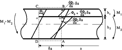
The upper and lower arm thickness are h1 and h2, and the bending moments applied on the upper and lower arms are M1 and M2, respectively. The angles Φ0, Φ1 and Φ2 represent the slopes of the beam, upper arm and lower arm, respectively. When the crack grows a length δa from O on section AB to O’ on section CD, the external work is:
For pure bending, the change in angle is given by:
where M is the moment, Ef is the flexural modulus and I is the second moment of area. Similarly, the strain energy is:
where Ef1, I1, Ef2, I2, Efeq and Ieq are the flexural moduli and second moments of the area in the section of the crack tip of the upper arm, lower arm and total specimen, respectively. Substituting (2) and (4) in (1), it can be reduced to the equation of the total fracture energy:
EquationEquation (5)(5)
(5) allows determining the total fracture energy of a crack between two arms. However, it is essential to the characterization of the mechanical behavior to define the contribution of mode I and mode II fracture.
2.1. Williams’ partitioning method
Williams[Citation30] proposed a partitioning method (WM) based on the assumptions that: (i) pure mode I exists when opposite moments act on the joint arms; and (ii) pure mode II is obtained when the curvature in the two arms are the same. This means:
where the bending stiffness ratio between upper and lower arms is:
Substituting (6) and (7) in (5), the equation of the total fracture energy can be reduced to:
Notice that no cross-product term is observed. Therefore, the partitioning can be obtained by rewriting EquationEquation (9)(9)
(9) as function of MI and MII:
Finally, the equations of mode I and mode II fracture can be written as:
WM is widely applied in the fracture characterization of symmetric cracks. However, literature has shown that it does not predict with accuracy the fracture mode ratio of cracks between asymmetric arms .[Citation18,Citation33,Citation34] The assumptions do not describe with precision the interaction between mode I and mode II fracture. Therefore, it is not recommended for the characterization of asymmetric cracks.
2.2. Strain-based partitioning method
The strain-based partitioning method (SBM), proposed by Arouche et al.,[Citation42] introduced a new criterion for the fracture mode partitioning. The main difference in comparison with the WM lies on the condition for pure mode I: it incorporates the condition of strain equivalence for mode pure mode I, identified by Ouyang[Citation44] and confirmed by Wang et al. [Citation41] In the case of pure mode II, similarly to WM, the SBM assumes that it is produced when both arms have the same curvature, as observed by Mollón et al. [Citation45] Therefore, the partitioning assumptions become: (i) the longitudinal strain distribution at the faying surfaces of both arms must be identical in order to produce pure mode I; and (ii) pure mode II is obtained when the curvature in the two arms are the same. This gives:
where β is the ratio between the longitudinal strain at the faying surfaces of the upper and lower arms, as follows:
Substituting (14) and (15) in (5), the equation of the total fracture energy is obtained:
EquationEquation (17)(17)
(17) shows that the mode I fracture energy affects the mode II fracture energy and vice-versa. Consequently, the equation can only be written in the form of:
EquationEquation (18)(18)
(18) displays a coupling function fc (MI, MII) beyond the functions of pure mode I and pure mode II – fI (MI) and fII (MII), respectively. This implies that the fracture mode partitioning is obtained when the coupling function fc (MI, MII) is zero. This is achieved in the condition of β = 1. Therefore, the specimen design condition of longitudinal strain equivalence has to be satisfied. It means:
In this case, the mode I and mode II equations of fracture energy are the same as in WM – EquationEquations (11)(11)
(11) and (Equation12
(12)
(12) ). However, the SBM has a different assumption from the partitioning method proposed by Williams, leading to a different equation for the total fracture energy (G) which considers a coupling function between pure modes. The SBM shows that the partitioning can only be obtained when the condition of beta equals 1 is respected, while WM ignores the coupling function that contributes to the total fracture energy and does not reinforce any specific specimen design. This is believed to be the reason why WM leads to inaccurate results for the partitioning of asymmetric specimens where the longitudinal strain-based design criterion is not applied (β ≠ 1). This assumption will be verified in this paper.
3. Numerical models
A virtual mixed-mode bending (MMB) test was chosen to evaluate the analytical fracture characterization method. In this test, a loading is applied through a roller attached to a lever and loaded just above the mid-plane of the test specimen, as shown in . The test loading (P) is decomposed in opening (PI) and shear (PII) loadings in a constant ratio determined by the lever length (c). A longer lever length c produces a fracture with higher portion of mode I.
Figure 2. MMB test model.
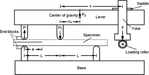
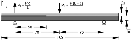
A 2D finite elements model was created in Abaqus (version 2019.HF2). shows the geometric features of the model: 70 mm half-span (L) and 50 mm crack length (a). The upper and lower arm thicknesses (h1 and h2, respectively) and materials (E1 and E2, respectively) are the parameters varied in the analysis. Loads and boundary conditions were applied to the model in order to simulate the MMB testing conditions. Mode I and mode II loads (PI and PII, respectively) were derived from a test load (P) of 100 N, according with the applied lever length (c). The specimen supports were modelled as a constraint from all displacements and rotations around x and y-axis, on the left side, and a constraint from displacements in y direction, on the right side, as shown in . Plane strain 4-nodes bilinear quadrilateral elements (CPE4) were applied in the whole geometry. Non-linear effects of large deformations and displacements are included in the analysis.
Figure 3. MMB test model.
The virtual crack closure technique (VCCT) was applied for calculation of the mode I and mode II fracture energy. The VCCT is a ‘local’ approach based on linear elastic fracture mechanics (LEFM). The method gives accurate results as long as the singular field is large compared to the damage zone.[Citation46] High values of critical fracture energy were inserted to ensure that the crack did not propagate. This allows obtaining the fracture energy at defined crack propagation points. The mesh sensitivity analysis was performed in two models with different conditions of asymmetry. The first model is an asymmetric crack between arms of the same material, and the second model is a bi-material crack. Both studies will be discussed hereafter.
3.1. Asymmetric crack within the same material
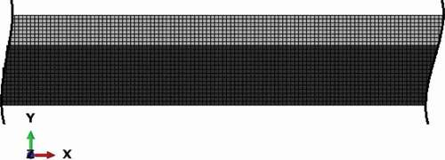
A mesh sensitivity analysis was performed on an asymmetric crack between arms of the same material. The model consists of an MMB test specimen with an upper arm thickness of 1.50 mm and a lower arm thickness of 3.00 mm. An elastic isotropic material was applied to both arms with Young’s modulus of 70 GPa and Poisson`s ratio of 0.33. The test loadings refer to lever length (c) of 61 mm. shows the fracture mode (GII/G) obtained from the node at the crack tip, using different square element sizes. The light grey color represents the upper adherend and the dark grew color describes the lower adherend. As can be seen, the model achieved good convergency. The mesh with elements of 0.20 mm presented a variation of 0.72% in the mode I fracture energy and 1.02% in the mode II fracture energy to the model with 0.10 mm elements. Therefore, the model with 20700 elements of 0.20 mm was selected for the numerical calculation of the fracture parameters, as shown in .
Figure 4. Fracture mode of an asymmetric crack within arms of the same material, in terms of the element size.
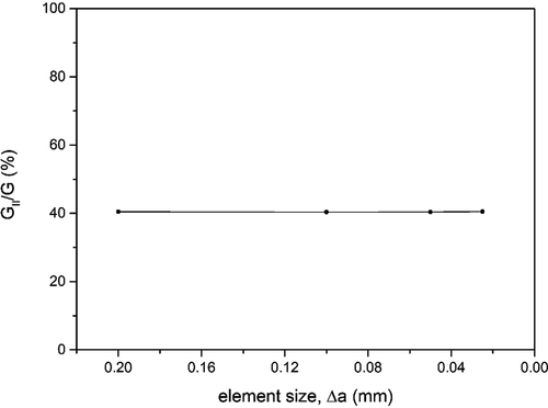
Figure 5. Mesh of model with arms of the same material.
3.2. Bi-material crack
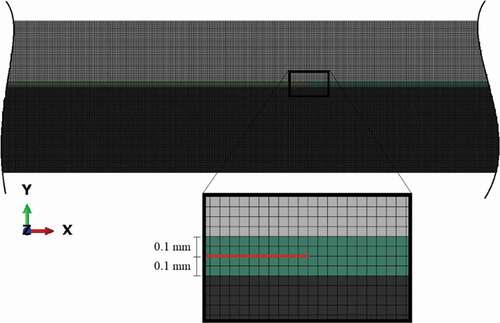
A second mesh sensitivity analysis was performed on a crack between arms made of different materials. The model consists of an MMB test specimen with an upper arm thickness of 2.12 mm and a lower arm thickness of 3.00 mm. Elastic isotropic materials were applied to both arms, with Young’s modulus of 140 GPa in the upper arm, 70 GPa in the lower arm, and Poisson`s ratio of 0.33 in both arms. In order to avoid mesh size dependent results in cracks between different materials, literature recommends modeling a thin interlayer and make the crack propagate within it.[Citation28,Citation34] Therefore, a 0.10 mm adhesive layer was inserted on both sides of the crack. The adhesive has Young’s modulus of 2.25 GPa and Poisson`s ratio of 0.38, and the inserted layer is thin enough to have a negligible effect (<1%) on the stiffness of the arms. shows the fracture mode (GII/G) obtained from the node at the crack tip, using different square element sizes. A good convergence is observed in the model with adhesive layer. The mesh with elements of 0.05 mm presented a variation of 0.29% in the mode I fracture energy and 0.44% in the mode II fracture energy to the model with 0.25 mm elements. Therefore, the model with 381600 elements of 0.05 mm was selected for the numerical calculation of the fracture parameters, as shown in . The light grey color represents the upper adherend, the dark grew color describes the lower adherend, and the green color is the interlayer.
Figure 6. Fracture mode of a bi-material crack, in terms of the element size.
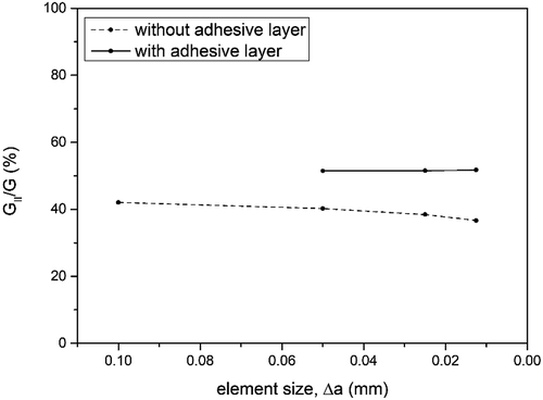
Figure 7. Mesh of model with bi-material crack.
4. Results and discussion
In this section, the results from the analytical methods are benchmarked against the numerical results. The total fracture energy and the fracture mode ratio are presented for the WM, the SBM (which coincides with the WM for β = 1, EquationEquation 16(16)
(16) ), and the finite elements model (FEM/VCCT). The arms thicknesses and materials vary, and therefore β. The accuracy of the analytical methods is verified for general specimen design. The aim is to verify the assumption proposed in the SBM that the accurate fracture mode ratio is only obtained if the longitudinal strain-based design criterion is applied (β = 1). This proposition is evaluated, firstly, for asymmetric cracks within the same material and, secondly, for bi-material cracks.
4.1. Asymmetric crack within the same material
The first parametric study was performed on an asymmetric crack within the same material. Both arms have Young’s modulus (E1 = E2) of 70 GPa and Poisson`s ratio (ν1 = ν2) of 0.33. In order to verify the influence of the fracture mode ratio in the accuracy of the analytical methods, three different conditions were considered: low (c = 117 mm), intermediate (c = 61 mm) and high (c = 42 mm) mode II ratio. shows the three cases of geometrical asymmetry. The upper arm thickness (h1) is varied in a wide range of geometries applied to the MMB test specimen while the lower arm thickness (h2) remains 3.0 mm. The crack length is kept at 50 mm and the test load (P) is 100 N.
Table 1. Study cases of geometrical asymmetry.
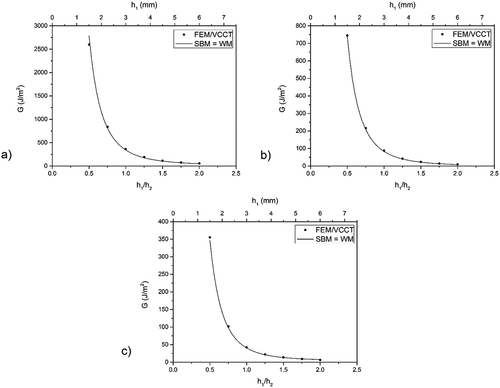
Analytical and numerical results of the total fracture energy (G) are presented in . Notice that the SBM – EquationEquation (17)(17)
(17) – gives the same total fracture energy as WM – EquationEquation (9)
(9)
(9) – for any geometry. This occurs because both methods are derived from the same equation of the total fracture energy – EquationEquation (5)
(5)
(5) . shows the three cases of low (case 1), intermediate (case 2) and high (case 3) mode II fracture, respectively. Overall, the total fracture energy obtained from analytical solutions based on beam analysis are in very good agreement with the numerical results.
Figure 8. Total fracture energy with the variation of the specimen thickness: cases (a) 1 – low, (b) 2 – intermediate and (c) 3 – high mode II.
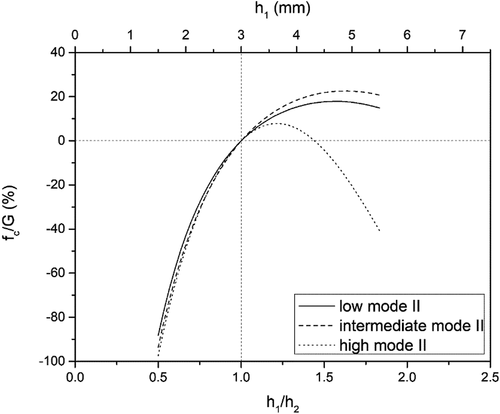
shows the analytical and numerical fracture mode ratio (GII/G). Notice that the SBM is applied only when the specimen design condition is satisfied (β = 1) and, for this condition, gives the same result of WM. ) shows the results for low mode II (case 1). When β = 1, the crack is symmetric (h1/h2 = 1) and both analytical methods show good agreement with numerical results. As β differs from 1, WM gives significant discrepancies from the FEM/VCCT results. This shows that WM is only valid for the condition β = 1. Similar results are observed as the mode II fracture ratio increases, in (cases 2 and 3, respectively). Moreover, it is noticeable that WM gives inaccurate fracture partitioning ratios on asymmetric cracks within the same material .[Citation33,Citation34] This can be explained by the influence of the mode I and mode II coupling on the fracture energy, shown in , which plots the coupling function (see EquationEquation 18)(18)
(18) over the total fracture energy (fc/G). It can be seen that the influence of the mode I and mode II coupling in the total fracture energy is zero in the case of a symmetric crack (β = 1). The coupling effect increases largely with the asymmetry of the specimen. This explains the fact that WM is not well suited for the mixed-mode fracture characterization of cracks between asymmetric geometries.
Figure 9. Fracture mode ratio with the variation of specimen thickness: cases (a) 1 – low, (b) 2 – intermediate and (c) 3 – high mode II.
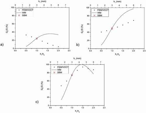
Figure 10. Influence of the coupling function on the fracture energy of cases 1 – low, 2 – intermediate and 3 – high mode II.
shows the results and errors of the analytical model in comparison with the numerical model for the condition of symmetric crack. Slight errors between −4.2% and −6.0% are observed in the calculation of the total fracture energy and between 2.6% and 7.6% in the fracture mode ratio. In the particular condition of a symmetric crack, literature suggests crack tip corrections in order to account for the effect of crack tip rotation under mode I[Citation31] and mode II[Citation32] fracture. The analytical method with the application of these correction factors presented insignificant errors for the calculation of the total fracture energy and errors lower than 4.0% for the fracture mode ratio – see . In both cases, the use of correction factors resulted in more accurate results. This shows that the effect of crack tip rotation during the experiments may have a non-negligible effect on the fracture behavior although the simple analytical model proved to be reliable.
Table 2. Results and errors of the analytical model in the condition of symmetric crack.
4.2. Bi-material crack
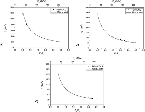
A second parametric study was carried out on a bi-material crack with asymmetric geometry. The upper arm has thickness (h1) of 2.12 mm and the lower arm has thickness (h2) of 3.0 mm. In order to verify the influence of the fracture mode ratio in the accuracy of the analytical methods, three different conditions were considered: low (c = 95 mm), intermediate (c = 49 mm) and high (c = 34 mm) mode II ratio. shows the three cases of bi-material crack. The upper arm Young’s modulus (E1) is varied in a wide range of reasonable specimen materials applied to the MMB test. The lower arm has Young’s modulus (E2) of 70 GPa and both arms have Poisson`s ratio (ν1 = ν2) of 0.33. The crack length is kept at 50 mm and the test load (P) is 100 N, likewise the previous cases.
Table 3. Study cases of bi-material crack.
Analytical and numerical results of the total fracture energy (G) are presented in . Both analytical methods give the same results for any material. shows the three cases of low, intermediate and high mode II fracture, respectively. Both analytical methods are in very good agreement with the FEM/VCCT results, hence, the analytical methods based on beam analysis provide reliable results of the total fracture energy on bi-material cracks.
Figure 11. Total fracture energy with the variation of the specimen material: cases (a) 4 – low, (b) 5 – intermediate and (c) 6 – high mode II.
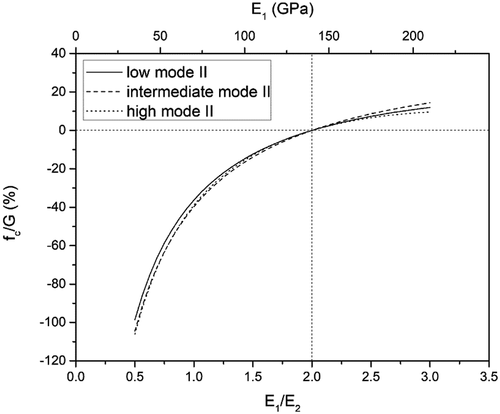
shows the analytical and numerical fracture mode ratio (GII/G). For the applied parameters, the strain-equivalent geometry (β = 1) is achieved when E1/E2 equals 2.0. In the case of low mode II (case 4), shown in ), the SBM shows good agreement with the FEM/VCCT despite the remarkable asymmetry of the materials and geometry. However, as β differs from 1, WM gives significant discrepancies from the FEM/VCCT results. This shows that the analytical method based on beam analysis is only valid for when the strain-equivalence condition is respected. Similar results are observed as the mode II fracture ratio increases, presented in (cases 5 and 6, respectively). Moreover, it is shown once more that WM is only valid when the condition of strain equivalence is satisfied (β = 1). For any other geometry, it gives incorrect fracture mode ratios because it ignores the coupling effect between fracture modes. shows that the coupling function fc is zero in the case of a strain-equivalent geometry (β = 1). In any other geometry, the influence of the mode I and mode II coupling may have a large effect on the fracture mode of bi-material cracks. This explains the requirement of the strain-based equivalent design criterion for obtaining the correct partitioning ratio.
Figure 12. Fracture mode ratio with the variation of specimen material: cases (a) 4 – low, (b) 5 – intermediate and (c) 6 – high mode II.
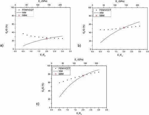
Figure 13. Influence of the coupling function on the fracture energy of cases 4 – low, 5 – intermediate and 6 – high mode II.
shows the results and errors of the analytical model in comparison with the numerical model for the particular condition of strain equivalence proposed in the SBM (see EquationEquation 19)(19)
(19) . Errors between 1.0% and −8.1% are observed in the calculation of the total fracture energy and between 1.1% and −8.6% in the fracture mode ratio. These errors are in a similar degree as cases 1, 2 and 3 of symmetric condition, presented in . Therefore, it can be implied that the effect of crack tip rotation is also a major cause of the errors produced in cases 4, 5 and 6 of bi-material cracks using the SBM.
Table 4. Results and errors of the analytical model in the condition of strain equivalence.
5. Case study
In this section, the mixed-mode fracture behavior of a bi-material bonded joint is determined from experiments using the SBM and the FEM. Composite-to-metal bonded specimens were manufactured in thin and thick geometries and tested using the MMB apparatus. The aim is to verify the accuracy of the SBM against significant shear effects and its limitations for the characterization of a crack propagation between different materials and geometry.
5.1. Materials and methods
Composite-to-metal bonded specimens were manufactured using similar materials and methods of composite repair application to metal structures in offshore industry.[Citation47] Specimens with two different geometries were produced, as shown in . Carbon steel plates (ASTM A36) with 6.35 mm and 3.18 mm thickness were selected for the metal adherend. The steel surface was blasted with steel grit (G-40) and degreased with acetone. An epoxy adhesive (NVT201E, Novatec, Brazil) with a glass transition temperature (Tg) of 80°C was applied. One layer of glass fiber chopped strand mat with a density of 300 g/m2 was inserted between the adherends on half of the plate. Bidirectional carbon fiber fabrics (LTC450-C10-C, DEVOLD AMT, Norway) with density of 430 g/m2 and epoxy lamination resin (PIPEFIX, Polinova S.A., Brazil) with a Tg of 116°C and working life of 30 minutes were selected for the composite adherend. The composite adherend was manufactured by hand lay up on the treated metal surface. The first unidirectional carbon ply in contact with the glass fiber mat was placed at the length direction (0º). Ten layers of 0/90º carbon fibers were laminated on the thin-metal plate and 20 layers were applied on the thick-metal plate. The adhesive and resin curing process occurred simultaneously in approximately 2 h at room temperature. The mechanical properties of the materials were obtained from a previous work[Citation48] and are shown in .
Table 5. Mechanical properties of the materials.
Figure 14. Specimen geometry (dimensions in mm).
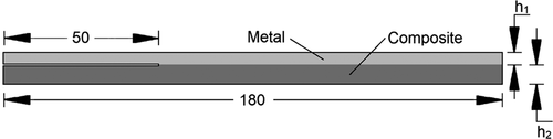
Specimens were cut from the plates using a bandsaw with a high-speed steel blade and cutting oil. Measurements of width and thickness were obtained with a digital caliper at 30 mm from both ends and at center of the specimens. The thick specimens have an average width of 24.9 ± 0.3 mm and an average thickness of 20.1 ± 0.4 mm. The thin specimens have an average width of 25.3 ± 0.2 mm and an average thickness of 9.5 ± 0.2 mm. The average length of both specimens is 180 ± 1 mm and was measured with a ruler. The specimen geometry was designed in accordance with the criterion of strain equivalence between arms (see EquationEquation 19)(19)
(19) although a high precision thickness of the composite materials is impracticable. An anti-friction material was applied between the metal plate and the adhesive in order to produce a pre-cracked region of 50 mm length.
MMB tests (see ) were performed using a servo-hydraulic testing machine (MTS 831, MTS Systems Corporation, United States of America) coupled with a 10 kN load cell. Specimens were positioned with the metal arm on top and the lever length (c) of 78 mm and 110 mm were set for the thick and thin samples, respectively. shows the test matrix. The half-span (L) of the test is 70 mm and the initial crack length (a0) of 30 mm was obtained after bonding the end-blocks. The testing load was applied at the quasi-static rate of 0.5 mm/min. with displacement control. Load-displacement points were obtained during the test and a high-resolution camera is positioned for crack length monitoring. The numerical results were obtained from the model of a bi-material crack, as described in section 3.2, with the actual properties presented in . Two tests were performed in each configuration, as shown in . The analytical results were calculated using the SBM using the same parameters as the numerical model. The input composite thickness was slightly adapted in order to have the required strain equivalence condition (see EquationEquation 19)(19)
(19) .
Table 6. Test matrix.
5.2. Results and discussion
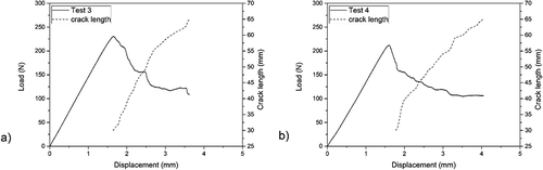
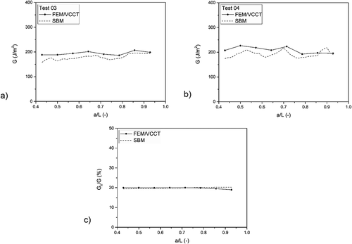
Results of the MMB tests in thick and thin composite-to-metal specimens are shown in , respectively. Crack propagation points were obtained for every 1 mm of crack step. Tests 1 and 2 in thick specimens (), respectively) reached maximum loads between 800 N and 1000 N at crack initiation and decreased to values between 600 N and 700 N at the final crack length of 65 mm with displacements near 1.5 mm. In the case of thin specimens, tests 3 and 4 (), respectively) presented maximum loads between 200 N and 250 N at crack initiation and values between 100 N and 150 N at the final crack length of 65 mm with displacements near 4.0 mm.
Figure 15. MMB test results of thick specimens.
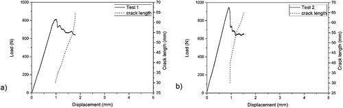
Figure 16. MMB test results of thin specimens.
The tested specimens have relatively thin adhesive layer with a brittle epoxy adhesive, which contributes for a negligible FPZ ahead of the crack tip. The finite element model was experimentally validated in a previous work[Citation42] using the same materials and methods. So, it can be assumed that the plastic zone is small, and the energy dissipated can be neglected in comparison to the elastic response. Therefore, the total fracture energy and mode ratio can be compared using the SBM and the VCCT.
) show the total fracture energy of Tests 1 and 2 in thick specimens. The SBM produced an error of 27.8% in the first measurement of crack propagation and reduced as the crack length increases, down to 11.4% in the last propagation point. The fracture mode ratio (GII/G) presented nearly constant values of 23.5% in the SBM and 21.5% in the FEM, as observed in ). A constant fracture mode ratio is expected from the MMB test. The total fracture energy of Tests 3 and 4, in thin specimens, are presented in ), respectively. Thick specimens produced an increase of fracture toughness due to a more unstable crack propagation while thin specimens presented stable crack growth and a clear plateau. In this geometry, the SBM produced an error of 13.2% in the first measurement of crack propagation and reduced as the crack length increases, down to 2.6% in the last propagation point. The analytical method produced more accurate results in the thin specimens compared to the thick ones. Moreover, the analytical solution showed more accuracy as the crack length increases, similarly to reference.[Citation42] These results are attributed to shear effects that are not considered in the analytical model but can be significant in specimens with relatively large thickness. Finally, thin specimens presented a nearly constant fracture mode ratio (GII/G) of 19.8% from both the SBM and the FEM ()). This shows the accuracy of the analytical solution and agrees with the results obtained from the parametric study in the previous section. Overall, the SBM gives reliable results for the calculation of the total fracture energy and mode ratio of bi-material crack as long as the shear effects are negligible.
Figure 17. Total fracture energy and mode ratio of thick specimens.
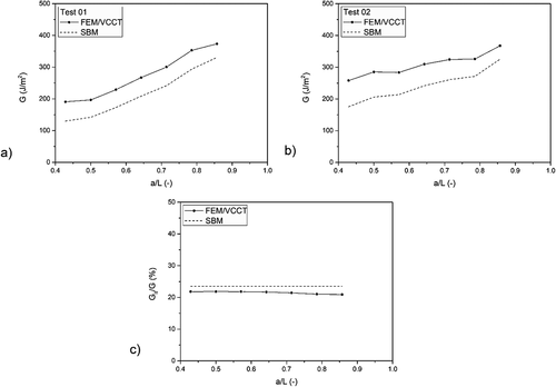
Figure 18. Total fracture energy and mode ratio of thin specimens.
6. Conclusions
In this work, the strain-based method (SBM) is evaluated for the mixed-mode fracture characterization of asymmetric cracks. The fracture energy at the crack tip of mixed-mode bending (MMB) is determined using SBM, the widely applied Williams’ partitioning method (WM) and finite element models using the virtual crack closure technique (VCCT). The total fracture energy and mode ratio is obtained for a wide range of specimen thicknesses and materials.
The analytical methods based on beam analysis give good predictions of the total fracture energy of crack propagation with geometrical and/or material asymmetry. However, WM does not consider the coupling effect of mode I and mode II fracture energy and for that reason produces incorrect results of the fracture mode ratio in asymmetric cracks.
The SBM predicts a coupling relationship between the pure modes that allows obtaining the fracture mode ratio of bi-material cracks through a simple design criterion based on the longitudinal strain equivalence between specimen’s arms. SBM shows to be a reliable method that allows characterizing the mixed-mode fracture of asymmetric cracks through a simple formulation. The main limitations of the SBM are the fact that transverse shear effects and crack tip rotation are not considered in the analysis. Using SBM in specimens with large thickness-to-length ratio may produce significant errors and, therefore, geometrical limitations should be considered in the specimen design. The incorporation of an effective crack length in the model to account for these effects is an interesting possibility to improve the application of the analytical method for bi-material specimens.
Disclosure statement
No potential conflict of interest was reported by the author(s).
Correction Statement
This article has been republished with minor changes. These changes do not impact the academic content of the article.
Additional information
Funding
References
- Budhe, S.; Banea, M. D.; de Barros, S. An Updated Review of Adhesively Bonded Joints in Composite Materials. Int. J. Adhes. Adhes. 2017, 72, 30–42. DOI: 10.1016/j.ijadhadh.2016.10.010.
- Mangalgiri, P. D. Composite Materials for Aerospace Applications. Bull. Mater. Sci. 1999, 22(3), 657–664. DOI: 10.1007/BF02749982.
- de Teixeira, F.; Sinke, S.; Failure, J. Analysis of Adhesively-bonded Skin-to-stiffener Joints: Metal–metal Vs. Composite–metal. Eng. Failure Anal. 2015, 56, 2–13. DOI: 10.1016/j.engfailanal.2015.05.023.
- de Teixeira, F.; Sinke J, S. Failure Analysis of Adhesively-bonded Metal-skin-to-composite-stiffener: Effect of Temperature and Cyclic Loading. Compos. Struct. 2017, 166, 27–37. DOI: 10.1016/j.compstruct.2017.01.027.
- Taub, A. I.; Krajewski, P. E.; Luo, A. A.; Owens, J. N. The Evolution of Technology for Materials Processing over the Last 50 Years: The Automotive Example. JOM. 2007, 59, 48–57. DOI: 10.1007/S11837-007-0022-7.
- McGeorge, D.; Echtermeyer, A. T.; Leong, K. H.; Melve, B.; Robinson, M.; Fischer, K. P. Repair of Floating Offshore Units Using Bonded Fibre Composite Materials. Compos. A. 2009, 40(9), 1364–1380. DOI: 10.1016/j.compositesa.2009.01.015.
- Saleh, M. N.; Saeedifar, M.; Zarouchas, D.; Teixeira de Freitas, S. Stress Analysis of Double-lap Bi-material Joints Bonded with Thick Adhesive. Int. J. Adhes. Adhes. 2020, 97, 102480. DOI: 10.1016/j.ijadhadh.2019.102480.
- Van Den Einde, L.; Zhao, L.; Seible, F. Use of FRP Composites in Civil Structural Applications. Constr. Build. Mater. 2003, 17(6–7), 389–403. DOI: 10.1016/S0950-0618(03)00040-0.
- Chaves, F. J. P.; da Silva, L. F. M.; de Moura, M. F. S. F.; Dillard, D. A.; Esteves, V. H. C. Fracture Mechanics Tests in Adhesively Bonded Joints. A Literature Review. J. Adhes. 2014, 90 12, 955–992. DOI:10.1080/00218464.2013.859075.
- Xiao, F.; Hui, C.-Y.; Kramer, E. J. Analysis of a Mixed Mode Fracture Specimen: The Asymmetric Double Cantilever Beam. J. Mater. Sci. 1993, 28(20), 5620–5629. DOI: 10.1007/BF00367838.
- Park, S.; Dillard, D. A. Development of a Simple Mixed-mode Fracture Test and the Resulting Fracture Energy Envelope for an Adhesive Bond. Int. J. Fract. 2007, 148(3), 261–271. DOI: 10.1007/s10704-008-9200-z.
- Russell, A. J.; Street, K. N. Moisture and Temperature Effects on the Mixed-Mode Delamination Fracture of Unidirectional Graphite/Epoxy Delamination and Debonding of Materials; ASTM International: West Conshohocken, PA, 1985, pp 349–370. DOI: 10.1520/STP36314S.
- Yoon, S. H.; Hong, C. S. Modified End Notched Flexure Specimen for Mixed Mode Interlaminar Fracture in Laminated Composites. Int. J. Fract. 1990, 43(1), R3–R9. DOI: 10.1007/BF00018129.
- Davidson, B. D.; Sundararaman, V. A Single Leg Bending Test for Interfacial Fracture Toughness Determination. International Journal of Fracture. 1996, 78(2), 193–210. DOI: 10.1007/BF00034525.
- Szekrényes, A. József, U. J. Over-leg Bending Test for Mixed-mode I/II Interlaminar Fracture in Composite Laminates. Int. J. Damage Mech. 2007, 161, 5–33. DOI:10.1177/1056789507060774.
- Reeder, J. R.; Crews Jr, J. H. Mixed-Mode Bending Method for Delamination Testing. AIAA J. 1990, 28(7), 1270–1276. DOI: 10.2514/3.25204.
- Reeder, J. R.; Crews Jr, J. H. Redesign of the Mixed-mode Bending Delamination Test to Reduce Non-linear Effects. J. Compos. Technol. Res. 1992, 14(1), 12–19. DOI: 10.1520/CTR10078J.
- Ducept, F. A Mixed-mode Failure Criterion Derived from Tests on Symmetric and Asymmetric Specimens. Composites Science and Technology. 1999, 59(4), 609–619. DOI: 10.1007/s11837-007-0022-7.
- Pereira, A. B.; de Morais, A. B. Mixed Mode I + II Interlaminar Fracture of Glass-epoxy Multidirectional Laminates – Part 2 Experiments. Compos. Sci. Technol. 2006, 66(13), 1896–1902. DOI: 10.1016/j.compscitech.2006.04.008.
- Kim, B. W.; Mayer, A. H. Influence of Fiber Direction and Mixed-mode Ratio on Delamination Fracture Toughness of Carbon/epoxy Laminates. Compos. Sci. Technol. 2003, 63(5), 695–713. DOI: 10.1016/S0266-3538(02)00258-0.
- Liu, Z.; Gibson, R. F.; Newaz, G. M. The Use of a Modified Mixed Mode Bending Test for Characterization of Mixed-Mode Fracture Behavior of Adhesively Bonded Metal Joints. The Journal of Adhesion. 2002, 78(3), 223–244. DOI: 10.1080/00218460210408.
- Stamoulis, G.; Carrere, N.; Cognard, J. Y.; Davies, P.; Badulescu, C. On the Experimental Mixed-mode Failure of Adhesively Bonded Metallic Joints. Int. J. Adhes. 2014, 51, 148–158. DOI: 10.1016/j.ijadhadh.2014.03.002.
- Droubi, M. G.; Mcafee, J.; Horne, R. C.; Walker, S.; Klaassen, C.; Crawford, A.; Prathuru, A. K.; Faisal, N. H. Mixed-mode Fracture Characteristics of Metal-to-metal Adhesively Bonded Joints - Experimental and Simulation Methods. Procedia Struct. Integr. 2017, 5, 40–47. DOI: 10.1016/j.prostr.2017.07.059.
- Oliveira, J. M. Q.; de Moura, M. F. S. F.; Silva, M. A. L.; Morais, J. J. L. Numerical Analysis of the MMB Test for Mixed-mode I/II Wood Fracture. Composites Science and Technology. 2007, 67(9), 1764–1771. DOI: 10.1016/j.compscitech.2006.11.007.
- de Moura, M. F. S. F Oliveira, J. M. Q.; Morais, J. J. L.; Dourado, N. Mixed-mode (I+II) Fracture Characterization of Wood Bonded Joints. Construction and Building Materials. 2011, 25(4), 1956–1962. DOI: 10.1016/j.conbuildmat.2010.11.060.
- Yoshihara, H. Initiation and Propagation Fracture Toughness of Solid Wood under the Mixed Mode I/II Condition Examined by Mixed-mode Bending Test. Engineering Fracture Mechanics. 2013, 104, 1–15. DOI: 10.1016/j.engfracmech.2013.03.023.
- Pereira, F. A. M.; de Moura, M. F. S. F.; Dourado, N.; Morais, J. J. L.; Silva, F. G. A.; Dias, M. I. R. Bone Fracture Characterization under Mixed-mode I + II Loading Using the MMB Test. Engineering Fracture Mechanics. 2016, 166, 151–163. DOI: 10.1007/BF00367838.
- Krueger, R. Virtual Crack Closure Technique: History, Approach, and Applications. Applied Mechanics Reviews. 2004, 57(2), 109–143. DOI: 10.1115/1.1595677.
- Pereira, A. B.; de Morais, A. B. Mixed Mode I + II Interlaminar Fracture of Carbon/epoxy Laminates. Compos. A. 2008, 39(2), 322–333. DOI: 10.1016/j.compositesa.2007.10.013.
- Williams, J. G. On the Calculation of Energy Release Rates for Cracked Laminates. Int. J. Fract. 1988, 36(2), 101–119. DOI: 10.1007/BF00017790.
- Williams, J. G. End Corrections for Orthotropic DCB Specimens. Comput. Sci. Technol. 1989, 35(4), 367–376. DOI: 10.1016/0266-3538(89)90058-4.
- Wang, Y.; Williams, J. G. Corrections for Mode II Fracture Toughness Specimens of Composites Materials. Composites Science and Technology. 1992, 43(3), 251–256. DOI: 10.1016/0266-3538(92)90096-L.
- Shahverdi, M.; Vassilopoulos, A. P.; Keller, T. Mixed-Mode I/II Fracture Behavior of Asymmetric Adhesively-bonded Pultruded Composite Joints. Eng. Fract. Mech. 2014, 115, 43–59. DOI: 10.1016/j.engfracmech.2013.11.014.
- de Morais, A. B.; Pereira, A. B. Mixed-mode I + II Interlaminar Fracture of Glass/epoxy Multidirectional Laminates – Part 1: Analysis. Compos. Sci. Tech. 2006, 66(13), 1889–1895. DOI: 10.1016/j.compscitech.2006.04.006.
- Harvey, C. M.; Wang, S. Experimental Assessment of Mixed-mode Partition Theories. Composite Structures. 2012, 94(6), 2057–2067. DOI: 10.1016/j.compstruct.2012.02.007.
- Wang, W.; de Teixeira, F.; Poulis, S.; Zarouchas D, J. A. A Review of Experimental and Theoretical Fracture Characterization of Bi-material Bonded Joints. Compos. Part B. 2021, 206, 108537. DOI: 10.1016/j.compositesb.2020.108537.
- Arouche, M. M.; Teixeira de Freitas, S.; de Barros, S. On the Influence of Glass Fiber Mat on the Mixed-mode Fracture of Composite-to-metal Bonded Joints. Composite Structures. 2021, 256, 113109. DOI: 10.1016/j.compstruct.2020.113109.
- Valvo, P. S. On the Calculation of Energy Release Rate and Mode Mixity in Delaminated Laminated Beams. Eng. Fract. Mech. 2016, 165, 114–139. DOI: 10.1016/j.engfracmech.2016.08.010.
- Conroy, M.; Kinloch, A. J.; Williams, J. G.; Ivankovic, A. Mixed Mode Partitioning of Beam-like Geometries: A Damage Dependent Solution. Eng. Fract. Mech. 2015, 149, 351–367. DOI: 10.1016/j.engfracmech.2015.06.061.
- Álvarez, D.; Guild, F. J.; Kinloch, A. J.; Blackman, B. R. K. Partitioning of Mixed-mode Fracture in Adhesively-bonded Joints: Experimental Studies. Eng. Fract. Mech. 2018, 203, 224–239. DOI: 10.1016/j.engfracmech.2018.04.032.
- Wang, W.; Fernandes, R. L.; Teixeira de Freitas, S.; Zarouchas, D.; Benedictus, R. How Pure Mode I Can Be Obtained in Bi-Material Bonded DCB Joints: A Longitudinal Strain-Based Criterion. Composites Part B: Engineering. 2018, 153, 137–148. DOI: 10.1016/j.compositesb.2018.07.033.
- Arouche, M. M.; Wang, W.; Teixeira de Freitas, S.; de Barros, S. Strain-based Methodology for Mixed-mode I+II Fracture: A New Partitioning Method for Bi-material Adhesively Bonded Joints. The Journal of Adhesion. 2019, 95(5–7), 385–404. DOI: 10.1080/00218464.2019.1565756.
- Arouche, M. M.; Saleh, M. N.; Teixeira de Freitas, S.; de Barros, S. Effect of Salt Spray Ageing on the Fracture of Composite-to-metal Bonded Joints. International Journal of Adhesion and Adhesives. 2021, 108, 102885. DOI: 10.1016/j.prostr.2017.07.059.
- Ouyang, Z.; Ji, G.; Li, G. On Approximately Realizing and Characterizing Pure Mode-I Interface Fracture between Bonded Dissimilar Materials. Journal of Applied Mechanics. 2011, 78(3), 031020. DOI: 10.1016/j.compositesa.2007.10.013.
- Mollón, V.; Bonhomme, J.; Argüelles, A.; Viña, J. Influence of the Crack Plane Asymmetry over GII Results in Carbon Epoxy ENF Specimens. Compos. Struct. 2012, 94(3), 1187–1191. DOI: 10.1016/j.compstruct.2011.10.025.
- Davidson, B. D.; Gharibian, S. J.; Yu, L. Evaluation of Energy Release Rate-based Approaches for Predicting Delamination Growth in Laminated Composites. International Journal of Fracture. 2000, 105(4), 343–365. DOI: 10.1023/A:1007647226760.
- Arouche, M. M.; Budhe, S.; Alves, L. A.; Teixeira de Freitas, S.; Banea, M. D.; de Barros, S. Effect of Moisture on the Adhesion of CFRP-to-steel Bonded Joints Using Peel Tests. J. Braz. Soc. Mech. Sci. Eng 2018, 40(1), 10. DOI: 10.1007/s40430-017-0959-6.
- Teixeira de Freitas, S.; Banea, M. D.; Budhe, S.; de Barros, S. Interface Adhesion Assessment of Composite-to-metal Bonded Joints under Salt Spray Conditions Using Peel Tests. Compos. Struct. 2017, 164, 68–75. DOI: 10.1016/j.compstruct.2016.12.058.