
ABSTRACT
Timber as construction material has a long tradition and is increasingly coming into focus as a renewable material in the planning and construction of buildings. Nevertheless, there are mechanical limitations, especially for multi-storey buildings or large spans. In order to enable large spans with small cross-sections, steel and timber can be combined in a hybrid cross-section for bending beams. In this case, the performance of the hybrid component decisively depends on the bond of the individual cross-sections. The aim of this publication is to compare and investigate different joining techniques for an efficient bond between timber and steel. Small-scale specimens were used to investigate different bonding methods: dowel-type fasteners, punched metal plate fasteners (PMPF) and adhesive bonds between timber and steel. Adhesive bonded specimens exhibited stiff but brittle behaviour. The adhesive bond remained intact in all tests, while shear failure could be detected in the timber. Adhesive bonds exhibited 93 times the stiffness of dowel fasteners and 5.5 times the stiffness of PMPF. The load carrying capacity increased by approximately 80% compared to dowel-type fasteners and 30% compared to PMPF, demonstrating the superior suitability of adhesive bonds for high performance timber-steel hybrid sections.
1. Introduction
1.1. Motivation
The reduction of CO2-emissions is considered the most significant leverage in fighting climate change. In Germany, the construction industry is the largest emitter of CO2.[Citation1] Therefore, it is important to maximize the use of materials that store CO2, such as timber or engineered wood products (EWPs). To achieve this goal, policy promotes and requires the use of wood as a building material in its Charter for Wood 2.0[Citation2] at the federal, and local levels.[Citation3] Due to this program, the state is compelled to favour public buildings and modernisations as timber or hybrid constructions, combining timber with other materials, whenever possible.[Citation3] However, timber structures are subject to several limitations, such as the requirement for large cross-sections when utilised in multi-storey or large-span constructions, where significant loads are imposed, and deformation criteria are critical.
1.2. Hybrid timber sections
There are several strategies to increase the mechanical performance of structural elements, i.e., to enable large spans or reduce cross-sections. When dealing with steel or aluminium, metallurgy may be used to significantly increase strength at the level of the material, leading to ultra-high strength steels unthinkable of decades ago.[Citation4] This is not an option for timber-based structural elements, as there is very little room to tweak wood’s natural properties other than favouring specific wood species. Additionally, wood, if considered as a raw material, has strong limitations about dimensions, both in terms of cross-section and lengths, not to talk about naturally induced defects (as knots).
Early on, timber engineering has addressed this issue by exploring possibilities of composite structures. Already in the Middle Ages carpenters used to combine several smaller wooden elements to larger ones, relying of mechanical interlocking supported by metallic connections.[Citation5,Citation6] A step further was taken with the introduction of glued-laminated timber (GLT, colloquially called glulam), which allowed for much more architectural and engineering freedom.[Citation7] As revolutionary as GLT is, it largely remained a linear – yet allowing for curvature in one plane – structural element. The next step was then taken by the introduction of cross-laminated timber.[Citation8] CLT, which broadly speaking, extended GLT’s concept of adhesively bonding smaller boards to form larger structural elements to planar elements. Both GLT and CLT heavily rely on adhesives to form what timber engineering refers to as engineered wood products (EWP).[Citation9] The list of EWP is not limited to GLT and CLT, as others, such as laminated veneer lumber (LVL), following similar principles exist, with variations thereof still being developed. Blaß and Frese[Citation10] combined hardwood, due to its superior strength, as top and bottom layers with softwood in the centre; Frese[Citation11] investigated hybrid beams with beech LVL in the tensile zone and spruce laminations in the rest of the cross-section. Such refinements in hybridisation result in significant increases in carrying capacity of between 20% and 60% compared to spruce glulam. Yet, such approaches, while having proved very valuable, can neither fundamentally tweak wood’s inherent low stiffness (expressed in terms of Young’s or shear modulus) nor strength (whatever tensile, compression or particularly shear) is of interest.
Engineers have resorted to combining wood with other materials, favouring those that provide for the stiffness and strength timber alone lacks. A particularly prominent and successful example of this is the combination of timber with concrete[Citation12–15] for example. Now largely used for flooring, the complimentary properties of timber and concrete enhance the performance of the so-called timber-concrete-composite (or TCC) floors, including bending stiffness, load-bearing capacity, dynamic response, airborne sound transmission, structural fire rating, and thermal mass.
Such combinations are also possible with a plethora of other materials,[Citation16] e.g., reinforced timber with steel, aluminium, fiberglass etc. The combination of timber and steel, which is in the focus of the research presented herein, has also been investigated, herein illustrated on three examples. Riola Parada[Citation17] summarized previous research on hybrid timber-steel beams, categorizing the methods into three types: (i) horizontal steel elements to strengthen the tensile and/or compressive zones, (ii) vertical steel elements to improve timber shear capacity, and (iii) a combination of both. Steel can be positioned inside or outside the timber cross-section in all categories. Nabati[Citation18] tested timber and steel combinations under 4-point bending on small-scale specimens (HxW = 46 × 46 mm), covering all three categories (i, ii and iii) defined above. The combination of inner vertical and outer horizontal steel elements showed the best results, with stiffness values 7 times higher, if compared to the reference situation without hybridization. Kia et al.[Citation19] found that hybrid timber-steel columns significantly increase stiffness and ultimate bearing load. Testing three column types – timber-only, hybrid without adhesive, and hybrid with adhesive – they observed a 24% and 102% increase in ultimate load for the hybrid columns without and with adhesive, respectively, compared to timber-only columns. The tested cross-sections are shown in . The tests simplified load introduction with a 25 mm thick metal plate to ensure a flat cross-section and facilitate analytical calculations while ensuring material interaction.
Figure 1. Excerpt of the tested column types in[Citation19].
![Figure 1. Excerpt of the tested column types in[Citation19].](/cms/asset/80adff98-93a4-461f-9a1d-eb446a101b21/gadh_a_2360498_f0001_oc.jpg)
1.3. Joining techniques within timber and hybrid timber structural elements
For timber-based hybrid sections or structures to achieve efficacy, it is essential that they are interconnected in a suitable manner, as otherwise the benefit of involving a material with superior mechanical performance alongside wood is wasted. Because of its inherent characteristics such as natural fibrous orthotropy and, depending on the type of loading and brittleness, timber permits only a restricted number of connections type. To not extend this introduction, the following will focus on connections permitting the transmission of shear, which is the one relevant for hybrid structures acting in flexion.
The first method to connect timber elements so to ensure the transmission of shear is mechanical interlocking. It is probably the oldest one, known in carpentry for centuries, if not millennia.[Citation5] Kerf connections, as used for TCC[Citation20,Citation21] are modern interpretations of mechanical connections for timber-based hybrid structures. Mechanical interlocking can also take the form of studs, nails, (self-tapping) screws, (glued-in) rods etc.[Citation22] Yet another variant is the consideration of light gauge steel nail-plate[Citation23] punched metal plate fasteners[Citation24] and therelike.
Dowel-type connections are widely utilised in timber engineering across various structural uses. Despite the century long experience, existing design rules primarily rely on empirical data and testing rather than a robust mechanical basis.[Citation25] This limitation still hinders the optimization of these connections, crucial for economically efficient structural designs. In most cases, doweled connections require some relative displacement to activate load-transmission, which results in relatively low stiffness. Despite first appearing as a particular case of mechanical interlocking, experiments and simulations on doweled connections have highlighted the impact of friction on the mechanical performance thereof.[Citation26] In the United States of America, flitch beams are a standard construction method in house construction, with design guides dating back to 1997.[Citation27] Flitch beams combine one or two vertical steel elements with outer timber components. The stiffness of the connection between the steel and the timber element of flitch beams is crucial for those systems, hence research projects investigated alternative methods like shot fired dowels.[Citation28]
Another, very performant, connection method for hybrid structures involving wood is offered using adhesives. Archaeology[Citation29] has shown that Neanderthals have already manufactured “hybrid” tools made of timber and stone, and there is recorded use of natural (casein-, gluten-based) adhesives, e.g., in carpentry, during antiquity and the medieval period. Since then, and particularly with the advent of adhesives based upon petrochemistry, e.g., phenolics, urethanes (including polyurethanes), and epoxies in the 20th century, adhesive has become an important joining method in timber engineering. On one hand it is the basis of manufacturing the aforesaid EWP (GLT, CLT, LVL), but also the most crucial element in high-performance joining techniques as glued-in rods.[Citation30–32] The following, only hybrid structures involving adhesives will be further discussed, for more global aspects related to timber and adhesives, refer to.[Citation33]
Adhesively bonded hybrid structures involving timber are manifold. To keep this introduction short, only two applications shall be discussed. Firstly, adhesively bonded TCC, that is the combination of timber with concrete, in which the connection is achieved by means of an adhesive layer. Tannert et al.[Citation34] is a good reference for a review of the state of the art, and the principles behind the concept. In their study, they investigated the structural response of small-scale shear specimen comparing the performance of self-tapping screws, an adhesive layer (2K-epoxy), and the combination thereof. Specimen with self-tapping screws showed ductile behaviour, adhesively bonded specimens failed brittlely, and hybrid systems exhibited distinct failure phases with increased slip post-adhesive failure. The hybrid approach provides a balance between ductility and stiffness, eliminating trade-offs in design. The second examples, by Vallée et al.[Citation35] considered the hybridization of adhesively bonded and (steel) dowel joints via steel plates. The investigations were carried out at the level of small-scale joints, complemented on large-scale trusses. Bonded connections outperformed doweled ones significantly in both strength (by around 40%) and stiffness (by over 300%). This advantage is attributed to immediate force transmission and node restraint in bonded connections, reducing deformation.
Yet, despite the mechanical superiority adhesive bonding allows for in the setting of timber-based hybrid structures, including in combination with steel, it is necessary to formulate some caveats related to the manufacturing process. The process requires much more care, involves long(er) waiting times due to curing, depends on qualified personnel, involves aspects as surface preparation, and requires controlled environmental conditions.[Citation33] All these aspects make adhesive bonding potentially prone to a series of imperfections and defects mechanical fastening is not subjected to.[Citation36] This, besides the lack of clear standardisation and codes, leads to the reluctance of practitioners, which is exacerbated when it comes to bonding operations on site. One possibility to mitigate such concerns consists in relocating as much as possible of adhesive bonding operations in workshops under controlled conditions. One of the many possibilities this translates into has recently be presented by Boretzki et al.[Citation37] and Myslicki et al.[Citation38] in a setting completely unrelated to timber engineering. The authors deliberately ignore at this point further potential issues related to bonding in general, including that involving timber, most notably the known significant dependency of strength (and to a lesser extent stiffness) on size, commonly referred to as size-effects, all of which they are well aware.[Citation36,Citation39–42]
1.4. Friction between timber and steel
Tests to determine the coefficient of friction between wood and steel have been performed as early as 1940[Citation43–45] and more recently with laminated veneer lumber (LVL) and steel.[Citation46] Mean friction coefficients between wood and steel of μs = 0.32 and μk = 0.27 were evaluated. Measures to increase the friction between wood and wood were also investigated, but discarded due to major uncertainties of success[Citation43,Citation47] However, as the results in[Citation25] and[Citation48] have shown, an increase in friction between wood and steel is feasible with a surface modification of the steel part. Based on these tests, different surface modifications were recently investigated by Aurand & Blaß[Citation49,Citation50] with the aim to increase the coefficient of friction in the shear plane of timber connections. For steel applications, the most promising modifications are either a milling or coating of the surface (section 2.4.1 of this manuscript describes the corresponding surface treatment in detail). This leads to an increase by a factor of more than two compared to the values found in the literature. However, the increase in friction depends on an appropriate contact pressure to ensure an even impression of the coated surface.
1.5. Scope of this paper
There are many ways to ensure the connection between timber and steel so to form hybrid structures. As the short review of the state of the art has shown, the use of dowels or bolts, and that of adhesives, to some extent represent two extreme situations. Dowel, while widely accepted and easy to implement, usually results in low mechanical performance, in particular regarding stiffness. Adhesively bonded connections, on the other hand, while extremely performant in both strength and stiffness, are still reluctantly considered by practitioners, in particular because of the more complicated manufacturing process involved. This paper investigates methods that mitigate between these two extremes, by combining adhesive bonding with mechanical fastening or with methods for increasing the roughness of the overlapping joining parts, and compares their performance to the aforesaid extremes.
2. Materials and methods
2.1. Materials
2.1.1. Timber and GLT
All test series were performed with spruce glued laminated timber GL24h according to DIN EN 14080. This type of timber was chosen as it is standard in European timber construction. In addition, analytical calculations on hybrid cross-sections with a full bond have shown that the material properties of GL24h complement each other very good with steel grade S355. The density of the timber (moisture content between 9.7 and 11.1%) used for the test specimens was measured and resulted to ρ = 433 ± 23 kg/m3, which is 3% above the mean value according to DIN EN 14080. The mean density of each test series is shown in . The relevant mechanical properties according to DIN EN 14080 are E0,mean = 11500 MPa, ft,0,k = 19.2 MPa and fv,k = 3.5 MPa. For the analytical calculation of the estimated loads, the characteristic properties were converted to mean values, assuming a normal distribution (according to DIN EN 14358[Citation51]). The respective coefficients of variation (COV) for the different material properties were assumed according to.[Citation52]
2.1.2. Steel
All test series in this paper were manufactured with the material combination of S355 steel and GL24h timber. Mechanical characteristics according to DIN EN 10025[Citation53] of S355 were used to analytically calculate the estimated loads. The Young’s modulus is therefore E = 210000 MPa and the characteristic yield strength is fy = 355 MPa. In contrast to timber construction, the average material properties are used as characteristic values in steel construction. Therefore, no further conversion of the material properties is necessary.
2.1.3. Adhesives
Four different adhesives were used for the specimens in this study. Two bisphenol-A epoxy systems (EP 1 and EP 2) and one polyurethane (PUR) adhesive were used to bond steel and timber. All adhesives were characterised in previous studies[Citation54,Citation55] as bulk in tension tests (acc. to DIN EN ISO 527–2[Citation56]), and both Young’s modulus and tensile strength determined. The stress-strain curves of EP 2 and PUR are shown in . Both adhesives show an almost linear behaviour at the beginning of the test. Then the stiffness decreases until the specimens fail brittle. The uniaxial tensile tests were performed at room temperature using a servo-hydraulic testing machine. Additionally, lap shear strength of EP1, EP2, and PU were determined on lap-shear samples (following DIN EN 1465[Citation57]) made of spruce. As all lap shear tests failed in the wooden substrate, resulting in data that shows no statistical difference (following an Analysis of Variance (ANOVA) at a significance level of 0.05) the results provided did not allow for indications on the adhesive’s intrinsic shear strength. All mechanical properties are illustrated in .
Figure 2. Stress-strain curve EP 2 and PUR.
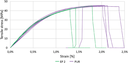
Table 1. Mechanical properties of the adhesives (lap shear strength on spruce).
2.1.4. Bolts
Bolts are a standard joining technique in timber engineering. A diameter of 10 mm and a length of 240 mm was used for the bolts, and a diameter of 50 mm for the washers (). Within the scope of this paper, tests with laterally loaded bolts were carried out. Tensile and bending tests according to DIN EN 409[Citation58] were performed to characterize the mechanical properties of the bolts. An average tensile capacity of 34.5 kN which equals fub = 660 MPa, and a yield moment of My = 58.6 Nm at a bending angle of 110°/d = 11° were reached.
2.1.5. Punched metal plate fasteners
The concept involved modifying steel profiles to interlock with timber. However, direct implementation on the steel surface was not possible. The PMPFs M 20 H by MiTek, essentially nails measuring 8.5 mm in length, with a 1 mm thick base plate, were adhesively bonded to the steel specimens using EP 3. They were then pressed into timber, utilizing their tooth-like structure. Made from strip galvanized S350 GD+Z, these PMPFs were approved for structural use in timber engineering.[Citation59] According to the manufacturer, the tensile strength of the material is Rm = 420 MPa and the characteristic tensile strength of the PMPF in the used x-direction is ft,0,k = 171 N/mm.[Citation59]
2.2. Test series and program
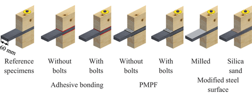
The test program was designed with a structured approach in mind. Initially, the aim was to compare the effects of different adhesives (EP1, EP2, and PUR). Subsequently, the impact of hybridization on two of these adhesives was examined. Following this, the influence of the PMPF, and finally, the effect of the steel surface condition was analysed. This systematic approach allowed for a methodical assessment of each variable’s contribution to the overall outcomes, ensuring a comprehensive understanding of the experimental results. All of these configurations were then tested against a reference case with fitting bolts only. illustrates the parameter investigated in each test series.
Figure 3. Test specimens.
2.3. Test specimens
The investigation regarding the different joining techniques is based on small-scale joint tests consisting of timber and steel parts. The specimens are designed symmetrically so to minimise bending moments. Therefore, each specimen has four shear planes. shows an exemplary test specimen with GL24h, S355 and the joining technique of adhesive bonding with additional bolts. The dimensions of the specimens were selected based on the ultimate loads of the joints with bolts. These joints were designed in such way, that the bolts become the decisive element with two plastic hinges per shear plane.
Figure 4. Specimen geometry, all dimensions in mm.
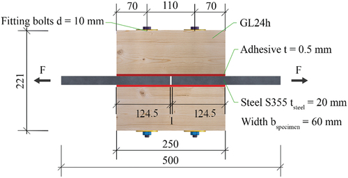
The estimated load-carrying capacity was determined analytically. For the first group, the European Yield Model (EYM) was used, according to DIN EN 1995-1-1 (Eurocode/EC 5[Citation60]). The estimated load for the joints with only bolts is calculated using mean values to Fest = 31.4 kN. As the load has to be transferred from the steel member to the timber members and back to the steel member with one bolt per joint, this load refers to one bolt with its two shear planes. Due to the lack of information about the influence of the roughened steel surface the same load is estimated as for the specimens without roughened surface. However, it can be expected that the maximum load capacity can be increased by the roughened surface.
The estimated load for the second group with continuous connection is calculated to Fest = 62.2 kN. This load refers to two shear planes with an effective area of Aeff = 14849 mm2. The expected failure mode is shear failure of the timber. The mean shear strength of timber was assumed to be fv = 4.2 MPa (with COV = 10%[Citation52]). Every specimen has four shear planes.
2.4. Manufacturing processes
As explained in Section 2.2, this paper compares three different joining techniques of steel and timber, i.e. adhesive bonding, bolts and PMPF. Every joining technique requires a specific manufacturing process. Therefore, the following sections describe all steps to manufacture the joint between steel and timber.
2.4.1. Joints with bolts
In the first test series, the specimens are joined with two M10 4.6 bolts (see section 2.1.4, one for each shear connection) with a length of 240 mm. Each joint consists of two timber side members and a steel middle member, thus resulting in two shear planes per fastener. The bolt holes were drilled in one step, using a special drill (Würth HSS smart step), to drill through both materials in the same process. The nuts were then tightened with 25 Nm.
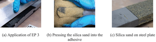
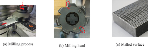
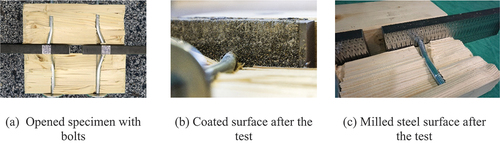
Additionally, two test series with bolts in combination with a roughened steel surface (see ) were investigated. For the first surface modification, silica sand was adhesively bonded with EP 3 on the steel, as shown in . The higher viscosity of EP 3, and its much higher filler content, required a adhesive thickness of approximately 0.5 mm. To achieve this, a tape with corresponding thickness was used on both ends of the adhesive layer. The adhesive was applied with a spatula between those tapes. Afterwards, excessive adhesive was removed with a metal profile using the tapes as a spacer for the defined adhesive thickness, see . The silica sand was then pressed by hand into the adhesive, see . Almost 90% of the grain size of the silica sand is between 0.5 and 0.8 mm. The steel plates coated with silica sand are shown in . The final step in the manufacturing process was to drill holes for the fitting bolts. The specimens were pre-stressed orthogonally by tightening the nuts to the same torque as the specimens without silica sand.
Figure 5. Manufacture of coated surface with silica sand.
For the second surface modification, a circular pattern was milled into the steel plate. This was achieved with a NC milling machine and the combination of a high rotation speed of the milling head, and a high feed rate of the steel plate (). Furthermore, only two of the removable inserts are attached to the milling head (). This results in the milling head only cutting out some parts of the steel surface (). The assembly of the specimens is equivalent to the specimens with silica sand and the specimens without a roughened surface.
Figure 6. Manufacture of milled surface.
2.4.2. Punched metal plate fasteners (PMPF)
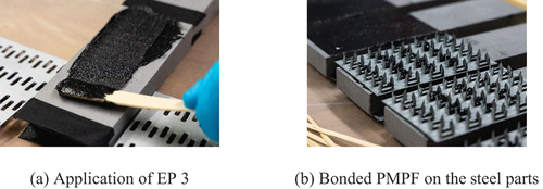
The PMPF were bonded to the steel surface with EP 3. The contact surfaces were sandblasted and degreased with methyl ethyl ketone (MEK). As the PMPF were not perfectly flat due to their manufacturing process, a thickness of 0.5 mm was insufficient for a continuous connection. Therefore, an adhesive thickness of approximately 1.5 mm was chosen. The adhesive was applied with a spatula () and trimmed with a metal plate. After applying the adhesive, the sandblasted side of the PMPF was pressed into it. Weights of 10 kg, resulting in a pressure of 0.013 MPa, were used to press the PMPF onto the steel plate while curing. The nails of the cured and bonded parts were then pressed into the timber parts, using a hydraulic press. One Test series specimens were tested in combination with PMPF and bolts. Holes for the bolts were drilled as the last step of production, similar to the test specimens without PMPF.
Figure 7. Manufacture of the specimens with PMPF.
2.4.3. Adhesively bonded
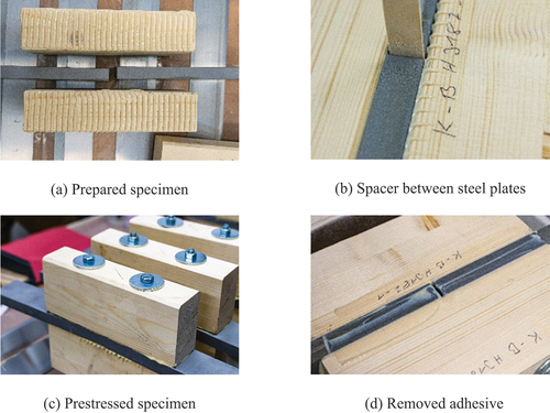
The preparation of the bonding parts has a major impact on quality and performance of the joint. To guarantee quality and replicability, steel parts of the joints were sandblasted to SA 2 ½ according to DIN EN ISO 8501–1[Citation61] and degreased with MEK. The PUR adhesive system requires an additional primer to prepare the surface. Timber surfaces were planed on the day of manufacturing. The timber and steel parts of the specimens with additional bolts were drilled before preparing the surface.
A notched spatula with 4 mm notches applied a 0.5 mm thick adhesive layer to timber parts, as seen in . A spacer was inserted between steel plates, covered with tape to prevent bonding (). Pre-stress perpendicular to the adhesive layer was applied to achieve a thickness of less than 0.5 mm. In preliminary tests, when employing this manufacturing method in conjunction with adherends crafted from acrylic glass, layer thicknesses ranging from 0.4 to 0.5 mm were attained. Specimens without bolts were pre-stressed using screw clamps, while those with bolts had nuts tightened to 25 Nm (). Excess adhesive was removed, and after curing, screw clamps were removed, leaving bolts tightened.
Figure 8. Manufacture of a specimen with adhesive.
2.5. Test procedure and evaluation
The tests are carried out according to DIN EN 26891.[Citation62] This standard describes the testing of timber joints with mechanical fasteners. For the tests a servo-hydraulic 250 kN testing machine was used. All tests were performed at room temperature. The specimens are force controlled loaded up to 40% of the estimated load and then unloaded up to 10%, with holding times of 30 seconds at each change of the load direction. The specimens are then loaded in displacement control until failure.
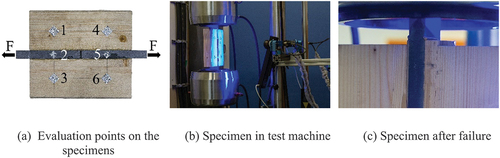
Deformations are measured using a DIC system from LIMESS Messtechnik u. Software GmbH, capable of recording both large (up to 15 mm) and small (down to 0.01 mm) displacements. Measuring points with a speckle pattern ensure accurate tracking. Six locations on each specimen are assessed, as shown in . Relative displacements between steel and timber are measured for each shear plane. Specimens are clamped in the testing machine (), and depicts a specimen after failure.
Figure 9. Test procedure.
For each specimen, the ultimate load is evaluated, as well as the stiffness in the range of 10% and 40% of the ultimate load. All results refer to the load/stiffness of one bolt, i.e. two shear planes. The figures in section 2.5 display the averaged load-displacement curves of every specimen in a test series in grey and one representative curve in colour. The representative specimens are then used for the discussion of the results in Chapter 4. For all test series, the load-displacement curves are cut of at the ultimate load by means of readability.
To determine the statistical significance of the various parameters on load-carrying capacity and stiffness, multiple analyses of variance (ANOVAs)[Citation63] with a significance level of α = 0.05 were conducted with OriginPro2023b.
3. Results
The following section illustrates the results of the tested joining techniques. All diagrams show the load on the y-axis and the displacement on the x-axis. Due to different stiffnesses, the scale illustrated in the figures differs between the joining techniques.
3.1. Joints with bolts
Measurements using the DIC system resulted in four load-displacement curves which were averaged for each specimen; only bolts are shown in , bolts and a silica sand coated steel surface in shows milled steel surface. All specimens show a stiff load-displacement behaviour at the beginning of the tests up to 6 to 10 kN. Afterwards the joining parts slide until the bolt is in contact with the edge of the clearance. The stiffness increases again and the load rises linearly. The hysteresis loop does not affect any additional slip. A loss of stiffness at a load level between 22 and 25 kN is followed by a nearly linear rise of the load with a lower stiffness until the maximum load of the specimens was reached.
Figure 10. Bolts with and without modified surface.
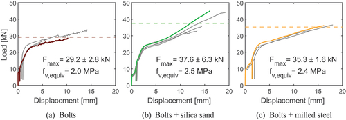
The maximum load is between Fmax = 29.2 kN (only bolts) and Fmax = 37.6 kN (bolts + silica sand). All results are tabulated in .
Table 2. Results.
After the maximum load, the specimens load drops slowly and incrementally without a significant load drop. shows opened specimens after the tests. Two plastic hinges are formed per bolt and shear plane and the timber begins to split.
Figure 11. Typical failure modes for specimens with bolts.
3.2. Punched metal plate fasteners (PMPF)
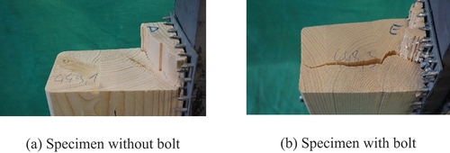
With increasing deformation, the load of the specimens with PMPF rises nearly linearly at the beginning of the tests. The hysteresis loop does not affect a slip or a loss of stiffness. With rising displacements, the stiffness decreases. Without bolts, a maximum load of Fmax = 42.5 kN was reached, which equals a shear stress of fv = 2.9 MPa. The specimens fail without a drop of the load, but with increasing displacements the load decreases until no residual load capacity is left. With bolts, the load reaches Fmax = 52.4 kN (fv = 3.5 MPa), and also fail without a drop of the load. Due to the bolts, the load decreases until a load level was reached at which only the bolts transmit the load. In the specimens with PMPF are shown after the tests (with large deformations, not shown in ). The failure occurs in the timber element, near to the nail tips. With bolts, the PMPF tips are pulled through the timber and the timber started splitting.
Figure 12. Specimens with PMPF with and without bolts.
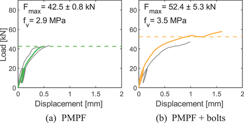
Figure 13. Fracture patterns of specimens with PMPF.
3.3. Adhesively bonded
The load-deformation behaviour of all specimens with an adhesive bond, with and without an additional bolt, are shown in . Specimens. The load-deformation behaviour is linear up to 40 kN. In the test series with EP 1 and bolts, the end faces of the steel parts are adhesively bonded on one specimen (shown in in grey as it is not the representative specimen). Since the force was transmitted via the steel-steel bonding at the beginning of the test, the initial load-displacement behaviour of this specimen is much stiffer. This connection fails at about 36 kN. Nevertheless, this specimen has the same load-displacement behaviour after the failure of the bond of the end faces. The hysteresis loop does not affect any slip or loss in stiffness. Afterwards, a gradual, minor reduction in stiffness until brittle failure can be observed at a maximum load between Fmax = 49.7 kN (EP 1) and Fmax = 65.9 kN (EP 1 + bolts). This corresponds to shear strength between fv = 3.4 MPa and fv = 4.4 MPa. Without additional bolts there is no residual load carrying capacity. With bolts, the load drop to a load level, where only the bolts transmit the load. The fracture patterns of the specimens without bolts are shown in . The failure of all test specimens is in the timber component close to the adhesive layer.
Figure 14. Test series with adhesive bond with and without bolts.
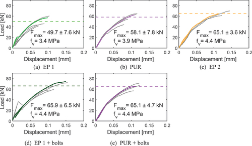
Figure 15. Fracture patterns of adhesively bonded specimens.
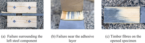
Figure 16. Fracture patterns of adhesively bonded specimens with bolts.
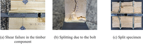
The fracture pattern of the specimens with adhesive bonding and bolts are shown in . Initial failure is shear failure of the timber, similar to the series without bolts. With further increasing machine displacement, load-displacement and failure behaviour are similar to the series with solely bolts. Yielding of the bolts as well as splitting of the timber parts occurs. shows the left side of a failed specimen, with relative displacement between timber and steel of the upper shear plane, while the lower shear plane is still intact. On the right side, the specimen failed at the lower shear plane, with the upper shear plane still intact. shows the end grain of one timber part after testing. The splitting as well as the shear failure are visible. shows an opened specimen with a failure surrounding the left steel element. The left bolt has two plastic hinges per shear plane, while the right bolt is not deformed. Section 4 offers a more detailed comparison between the specimens with and without bolts. The post-peak behaviour of exemplary tests is shown in . All specimens without additional bolts show brittle failure without residual load-carrying capacity. The specimens with bolts also show brittle failure, but with residual load-carrying capacity.
3.4. Summary of test results
In summary, shows the results of all tested joining techniques. Besides the ultimate load and the displacement at the ultimate load, the equivalent shear stress and the stiffness between 10% and 40% of the ultimate load are shown.
4. Discussion
4.1. Comparison of joints with bolts
Figure 17. Influence of the steel surface.
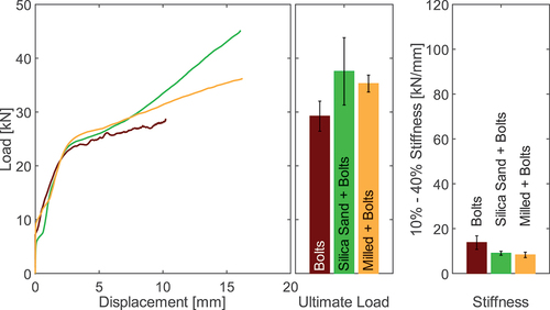
The load-displacement behaviour and the stiffness of the specimens with only bolts to the specimens with bolts and a modified steel surface is compared in . The reference specimens without a modified surface exceed the static frictional force between 6–7 kN. Specimens with adhesively bonded silica sand on the steel surface exceed this point between 5–6 kN. The pre-stress caused by the bolts is insufficient to press the sand into the timber surface. However, with increasing displacements, the rope effect presses the sand properly into the timber parts, thus increasing the load capacity due to mechanical interlocking. The rope effect is a phenomenon observed in laterally loaded timber connections, where the withdrawal resistance of fasteners, such as nails and screws, significantly impacts the load-bearing capacity. This effect is particularly pronounced in slender dowel-type connections.[Citation64] The milled steel surface results in an increase of the static frictional force to more than 9 kN. Two one-way ANOVAs were conducted to investigate the significance of the higher friction of the modified surfaces (silica sand and milled) on the stiffness (p = 0.016) and the ultimate load (p = 0.097). This confirms that the modified surface has a significant influence on the stiffness, but not on the ultimate load. The mean stiffness of the series with bolts is slightly higher than of the corresponding series with modified surfaces. Due to the higher static friction in relation to the ultimate load, specimens without modified surface are stiffer between 10% and 40% of the ultimate load. The stiffness of every tested series is calculated in . On average, the stiffness of all test series with bolts is 10.3 kN/mm with a standard deviation of 2.4 kN/mm.
In this test group with bolts, it is evident that for each joining technique, the expected failure mode involves the occurrence of two plastic hinges, as demonstrated in . The specimens without a modified surface were unable to achieve the analytically estimated load of 31.4 kN for this failure mode. Conversely, as anticipated, specimens with a roughened surface surpassed the estimated load due to increased friction. The investigations on roughened surfaces show that the static friction can be increased. The challenge is to generate a sufficiently high perpendicular pressure that allows interlocking with the timber surface. As described, this can be achieved with the milled surface in the present investigations and the perpendicular pressure was not high enough to properly press the sand into the timber surface.
4.2. Comparisons of specimens with punched metal plate fasteners (PMPF)
The test series of the specimens with PMPF are illustrated in . The load-displacement behaviour shows a very similar curve for both test series until the specimens without additional bolts fail. The specimens with additional bolts reach higher ultimate loads, the curve flattens after exceeding the ultimate load of the specimens without bolts. Due to the displacements of over 0.5 mm, there is no clearance around the bolt and force can be transmitted in the timber element. The presence of an additional bolt does not exert a significant influence on either the ultimate load (p = 0.091) or the stiffness (p = 0.253). Nevertheless, due to the limited number of specimens, further testing of specimens with this joining technique is required to statistically confirm those results.
Figure 18. All test series with PMPF.
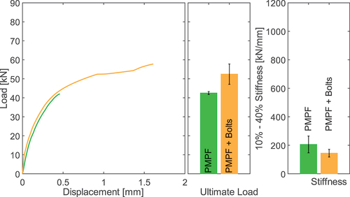
Specimens with PMPFs show a stiffness of 206 ± 59 kN/mm and specimens with PMPFs and additional bolts provide a stiffness of 144 ± 27 kN/mm. The averaged stiffness of all specimens with PMPFs results in 175 kN/mm with a standard deviation of 31 kN/mm.
Figure 19. Post-peak behaviour specimens PMPF.
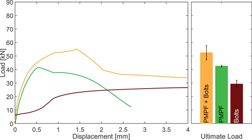
To illustrate the post-peak behaviour, shows displacements up to 4 mm on the x-axis. Both series with PMPFs show ductile behaviour after failure. No sudden loss in transferable load occurs. This might be explained by the condition of the fracture surfaces. Since the specimens failed in the layer of the nail tips, a very rough surface is created. Although, in the specimen with PMPF without bolts, shear failure separates the specimen completely, residual loads can be transferred. As the specimen is clamped into the testing machine, lateral displacement of the separated parts is prevented. This leads to considerable friction in the fracture surfaces, which results in a residual load.
For the series with additional bolts, shear failure occurs at a displacement of about 2 mm. Afterwards, the combination of rough shear surface and orthogonal force from the bolts, results in a nearly constant residual load even for displacement above 4 mm.
4.3. Comparison of adhesively bonded joints
To compare the five adhesively bonded test series, shows an exemplary load displacement curve for each series on the left side. The displacement on the x-axis is further scaled to 0–0.2 mm due to the much higher stiffness. As shown in the left diagram of , the qualitative behaviour is similar for all specimens. All specimens, regardless of the adhesive used or the use of additional bolts, showed a shear failure in the timber component.
Figure 20. All test series with adhesive bonding.
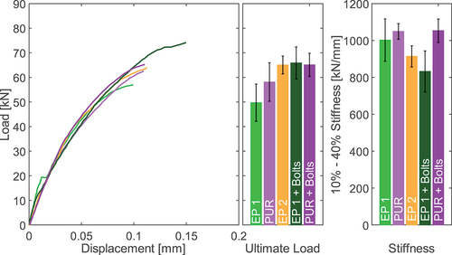
Two one-way ANOVAs (EP1, PUR and EP2) were conducted to investigate the significance of the influence of the adhesives on the ultimate load and the stiffness of the specimens. No significant influence was found on the ultimate load (p = 0.064) and the stiffness (p = 0.172). A two-way ANOVA (EP1, EP1+bolts, PUR and PUR + bolts) showed, that there is a significant influence on the ultimate load of the additional bolts (p = 0.004). A second two-way ANOVA of this group shows that there is no significant influence of the additional bolt on the stiffness (p = 0.103).
The exemplary post-peak behaviour of one specimen with EP 1 and bolts, one specimen with EP 1 and one reference specimen without adhesive is shown in . The specimen with EP 1 and additional bolts shows a brittle failure of two shear planes at 73 kN and 0.16 mm of deformation. As result, the load drops to 2.3 kN and the specimen slips up to 0.3 mm. From this point the bolt presses against the timber and transfers the load. The hole clearance of the bonded specimens with additional bolts is smaller than that of specimens with solely bolts. This could be due to excess adhesive filling the hole clearance and the different manufacturing process. With increasing displacements, the load capacity rises again until the yielding point of the bolt is reached at about 18 kN and 0.4 mm of displacement. The reference specimen showed a much lower stiffness compared to the bonded specimens, after exceeding the static friction. The point of yielding is reached at 20 kN and about 1 mm of displacement. At greater displacements over 1 mm, both specimens with bolts (with and without adhesive) have a similar load deformation behaviour, since the bolts transfer the load.
Figure 21. Post-peak behaviour EP 1.
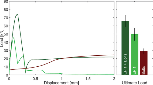
In comparison to the specimens with bolts (with and without adhesive), the specimen without bolts shows a different behaviour. The initial shear plane fails at 46 kN with a displacement of 0.09 mm. Following a drop in load to 13 kN, the load capacity subsequently increases until a second shear plane fails at approximately 24 kN with a displacement of 0.27 mm. As a result of this second failure, the structure loses all remaining load-carrying capacity. A load plateau sets in at about 5 kN. This is due to the clamping of the steel components, which generates transversal constraint on the specimen. The fracture patterns generate friction, which results in measurable residual load. After approximately 1 mm of displacement, residual load is reduced to a minimum.
4.4. Classification of stiffness groups and applicability in bending beams
Figure 22. Load displacement behaviour of all test series.
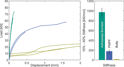
All test series can be categorized into three groups, which differ significantly in their ultimate load and stiffness. shows the load-displacement behaviour up to displacements of 2 mm. The right diagram in shows the mean stiffness for each category (between 10% and 40% of the ultimate load). The stiffness of 970 kN/mm ± 85 kN/mm of the adhesively bonded specimens is approximately 5.5 times higher than of the series with PMPF (175 kN/mm ± 31 kN/mm) and approximately 93 times higher than for the series with bolts (10.3 kN/mm ± 2.4 kN/mm). Besides the stiffness benefit of the adhesive bonding, the averaged ultimate load of these test series is 60.8 kN ± 6.2 kN and 1.3 times higher than for the series with PMPF (47.5 kN ± 5.0 kN) and 1.8 times higher than for the series with bolts (34.0 kN ± 6.2 kN). The load displacement behaviour up to 6 kN is very similar for all test series. Since the static frictional load depends on the contact stress in the shear plane, a higher preloading of the bolts would cause a higher frictional load. However, the limiting factor here is the compressive strength perpendicular to the grain of the timber. All specimens with bolts were produced with washers with a diameter of 5 cm and A = 18.5 cm2. This results in a maximum tensioning of the bolt of F = 5.5 kN (with f,c,90 = 3.0 N/mm2). The long-term behaviour of timber under compression perpendicular to the grain will be tested in further investigations of the research project. In order to efficiently manufacture hybrid timber-steel bending beams, the objective is to establish a shear-resistant bond that enhances load-bearing capacity. This is successfully achieved through comprehensive adhesive bonding across the entire surface area between the steel and timber components, as anticipated. However, from a manufacturing technology standpoint, the adhesive bond poses challenges, necessitating heightened efforts to ensure quality during production. The concept of adhesively bonded PMPFs was devised to adapt steel profiles for interlocking with timber, thereby combining the benefits of high shear stiffness with the ability to apply adhesive bonding in advance, within controlled workshop conditions. Classical bolted joints, regardless of steel surface modifications, exhibited insufficient shear stiffness. The ongoing research includes the application and validation of hybrid timber-steel beams, employing both adhesive bonding and adhesively bonded PMPFs, with findings planned for presentation in an upcoming publication.
5. Conclusions
In this study, different timber-steel joining techniques were tested in tensile shear tests. Both classic, state-of-the-art and innovative joining concepts were applied and analysed. The materials GL24h and S355 were joined with bolts (in combination with roughened joining part surfaces), PMPFs and adhesive bonding. Subsequently, the main results are summarised:
– Significant differences in joint stiffness for different joint types (low stiffness for bolted joints, joints with PMPF 5.5 times stiffer than bolted joints, bonded joints 93 times stiffer than bolted joints)
– Highest load for bonded joints, somewhat lower for PMPF (−21%), significantly lower for bolted joints (−44%)
– Ductile failure for bolted joints with two plastic hinges per shear plane and splitting of timber element
– Brittle shear failure in timber element for bonded joints and joints with PMPF
– Ductile post-failure behaviour for bonded joints as well as joints with PMPF through additional bolts
Due to their high load capacity and joint stiffness, joining methods with adhesive bonding and interlocking with PMPFs are presented as promising options for the usage in bending beams.
Disclosure statement
No potential conflict of interest was reported by the author(s).
Additional information
Funding
References
- Bundesinstitut für Bau-, Stadt- und Raumforschung. Umweltfußabdruck von Gebäuden in Deutschland. 2020. https://www.bbsr.bund.de/BBSR/DE/veroeffentlichungen/bbsr-online/2020/bbsr-online-17-2020-dl.pdf?__blob=publicationFile&v=3.
- Bundesministerium für Ernährung und Landwirtschaft. Charta für Holz 2.0. 2016. https://www.charta-fuer-holz.de/.
- Ministerium für Ernährung, Ländlichen Raum und Verbraucherschutz. Holzbau-Offensive Baden-Württemberg. 2018. https://www.holzbauoffensivebw.de/de.
- Li, J.; Zhan, D.; Jiang, Z.; Zhang, H.; Yang, Y.; Zhang, Y. Progress on Improving Strength-Toughness of Ultra-High Strength Martensitic Steels for Aerospace Applications: A Review. J. Mater. Res. Technol. 2023, 23, 172–190. DOI: 10.1016/j.jmrt.2022.12.177.
- Hewett, C. A. English Historic Carpentry; The History Press: Cheltenham, 2022, ISBN: 978-1-80399-052-1.
- Herzog, T.; Natterer, J.; Schweitzer, R.; Volz, M.; Winter, W. Timber Construction Manual,; KG: DETAIL - Institut für internationale Architektur-Dokumentation GmbH & Co, 2004.
- Dietsch, P.; Tannert, T. Assessing the Integrity of Glued-Laminated Timber Elements. Constr. Build. Mater. 2015, 101, 1259–1270. DOI: 10.1016/j.conbuildmat.2015.06.064.
- Kurzinski, S.; Crovella, P.; Kremer, P. Overview of Cross-Laminated Timber (CLT) and Timber Structure Standards Across the World. Mass. Timber. Constr. J. 2022, 5(1). DOI: 10.55191/MTCJ.2022.1.
- Yadav, R.; Kumar, J. Engineered Wood Products As a Sustainable Construction Material: A Review, Engineered Wood Products for Construction; 2022. DOI: 10.5772/intechopen.99597.
- Blaß, H. J.; Frese, M. Biegefestigkeit von Brettschichtholz-Hybridträgern mit Randlamellen aus Buchenholz und Kernlamellen aus Nadelholz, Universitätsverlag, Karlsruhe, 2006, ISBN: 978-3-86644-072-2.
- Frese, M. Hybrid Glulam Beams Made of Beech LVL and Spruce Laminations. Proceedings of the International Network on Timber Engineering Research, International Network on Timber Engineering Research Meeting 47, Bath, UK, 2014.
- Ceccotti, A. Composite Concrete-Timber Structures, Prog. Struct. Engng. Mater. 2002, 4(3), 264–275. DOI: 10.1002/pse.126.
- Yeoh, D.; Fragiacomo, M.; De Franceschi, M.; Heng Boon, K. State of the Art on Timber-Concrete Composite Structures. J. Struct. Eng. 2011, 137(10), 1085–1095. DOI: 10.1061/(ASCE)ST.1943-541X.0000353.
- Dias, A.; Skinner, J.; Crews, K.; Tannert, T. Timber-Concrete-Composites Increasing the Use of Timber in Construction. Eur. J. Wood Prod. 2016, 74(3), 443–451. DOI: 10.1007/s00107-015-0975-0.
- Tannert, T.; Ebadi, M. M.; Gerber, A. Serviceability Performance of Timber Concrete Composite Floors, Mocs; 2019. DOI: 10.29173/mocs95.
- William, M. B. Reinforcement of Wood Materials: A Review. Wood. Fiber. Sci. 1983, 16(3), 1984.
- Riola-Parada, F. Timber-Steel Hybrid Beams for Multi-Storey Buildings. Dissertation, Technische Universität Wien, 2016.
- Nabati, A.; Ghanbari-Ghazijahani, T.; Valipour, H. R. Innovative Flitch Sandwich Beams with Steel Core Under Four-Point Bending. Eng. Struct. 2021, 233, 111724. DOI: 10.1016/j.engstruct.2020.111724.
- Kia, L.; Valipour, H. R. Radiata Pine and Douglas Fir Timber Steel Encased Columns Subjected to Concentric and Eccentric Loading. J. Struct. Eng. 2022, 148(2). DOI: 10.1061/(ASCE)ST.1943-541X.0003266.
- Hehl, S.; Tannert, T.; Meena, R.; Vallee, T. Experimental and Numerical Investigations of Groove Connections for a Novel Timber-Concrete-Composite System. J. Perform. Constr. Facil. 2014, 28(6). DOI: 10.1061/(ASCE)CF.1943-5509.0000549.
- Shahnewaz, M.; Jackson, R.; Tannert, T. CLT Concrete Composite Floors with Steel Kerf Plate Connectors. Constr. Build. Mater. 2022, 319, 126092. DOI: 10.1016/j.conbuildmat.2021.126092.
- Marchi, L.; Scotta, R.; Pozza, L. Experimental and Theoretical Evaluation of TCC Connections with Inclined Self-Tapping Screws. Mater. Struct. 2017, 50(3). DOI: 10.1617/s11527-017-1047-1.
- Karadelis, J. N.; Brown, P. Punched Metal Plate Timber Fasteners Under Fatigue Loading. Constr. Build. Mater. 2000, 14(2), 99–108. DOI: 10.1016/S0950-0618(00)00015-5.
- Timber Engineering; Thelandersson, S., Larsen, H. J., eds. : Chichester: Wiley & Sons Ltd, 2003.
- Dorn, M.; De Borst, K.; Eberhardsteiner, J. Experiments on Dowel-Type Timber Connections. Eng. Struct. 2013, 47, 67–80. DOI: 10.1016/j.engstruct.2012.09.010.
- Sjödin, J.; Serrano, E.; Enquist, B. Experimentelle und rechnerische Untersuchung des Einflusses von Reibung in Verbindungen mit einem Stabdübel. Holz Roh Werkst 2008, 66(5), 363–372. DOI: 10.1007/s00107-008-0267-z.
- DeStefano, J.; MacDonald, J. Design Guides for Flitch Plate Beams and Lally Columns. 1997. https://dcstructural.com/pdfs/technical/1997_design_guides_for_flitch_plate_beams.pdf.
- Shot Fired Dowel Flitch Beams. 2005. https://www.oregon.co.uk/wp-content/uploads/2015/12/shot-fired-dowel-flitch-beams.pdf.
- Koch, T. J.; Schmidt, P. Adhesive Strength and Rupture Behaviour of Birch Tars Made with Different Stone Age Methods. J. Paleo. Arch. 2023, 6(1). DOI: 10.1007/s41982-023-00135-1.
- Tlustochowicz, G.; Serrano, E.; Steiger, R. State-Of-The-Art Review on Timber Connections with Glued-In Steel Rods. Mater. Struct. 2011, 44(5), 997–1020. DOI: 10.1617/s11527-010-9682-9.
- Steiger, R.; Serrano, E.; Stepinac, M.; Rajčić, V.; O’Neill, C.; McPolin, D.; Widmann, R. Strengthening of Timber Structures with Glued-In Rods. Constr. Build. Mater. 2015, 97, 90–105. DOI: 10.1016/j.conbuildmat.2015.03.097.
- Zhang, H.; Li, H.; Dauletbek, A.; Lorenzo, R.; Corbi, I.; Corbi, O. Research Status of Glued-In Rods Connections in Wood Structures. J. Build. Eng. 2023, 65, 105782. DOI: 10.1016/j.jobe.2022.105782.
- Vallée, T.; Tannert, T.; Fecht, S. Adhesively Bonded Connections in the Context of Timber Engineering – a Review. J. Adhes. 2017, 93(4), 257–287. DOI: 10.1080/00218464.2015.1071255.
- Tannert, T.; Gerber, A.; Vallee, T. Hybrid Adhesively Bonded Timber-Concrete-Composite Floors. Int. J. Adhes. Adhes. 2020, 97, 102490. DOI: 10.1016/j.ijadhadh.2019.102490.
- Vallée, T.; Tannert, T.; Hehl, S. Experimental and Numerical Investigations on Full-Scale Adhesively Bonded Timber Trusses. Mater. Struct. 2011, 44(10), 1745–1758. DOI: 10.1617/s11527-011-9735-8.
- Vallée, T.; Kaufmann, M.; Adams, R. D.; Albiez, M.; Correia, J. R.; Tannert, T. Are Probabilistic Methods a Way to Get Rid of Fudge Factors? Part I: Background and Theory. Int. J. Adhes. Adhes. 2022, 119, 119. DOI: 10.1016/j.ijadhadh.2022.103255.
- Boretzki, J.; Albiez, M.; Myslicki, S.; Vallée, T.; Ummenhofer, T. Hybrid Grouted Joints: Load Bearing and Failure Behaviour Under Static, Axial Loading. Constr. Build. Mater. 2024, 413, 134691. DOI: 10.1016/j.conbuildmat.2023.134691.
- Myslicki, S.; Vallée, T.; Fricke, H.; Ummenhofer, T.; Boretzki, J.; Albiez, M. Hybrid Grouted Steel Connections Using Adhesively Bonded Granules in the Steel Grout Interface: Development and Validation of an Innovative Joining Technique. Constr. Build. Mater. 2024, 414, 134765. DOI: 10.1016/j.conbuildmat.2023.134765.
- Vallée, T.; Kaufmann, M.; Adams, R. D.; Albiez, M.; Correia, J. R.; Tannert, T. Are Probabilistic Methods a Way to Get Rid of Fudge Factors? Part II: Application and Examples. Int. J. Adhes. Adhes. 2023, 124, 103364. DOI: 10.1016/j.ijadhadh.2023.103364.
- Myslicki, S.; Vallée, T.; Kaufmann, M.; Ummenhofer, T.; Boretzki, J.; Albiez, M. Harnessing the Synergy of Grout and Adhesive: Numerical Prediction of Load Capacity in Hybrid Composite Joints. Int. J. Adhes. Adhes. 2024, 130, 103602. DOI: 10.1016/j.ijadhadh.2023.103602.
- Albiez, M.; Vallée, T.; Fricke, H.; Ummenhofer, T. Adhesively Bonded Steel Tubes — Part I: Experimental Investigations. Int. J. Adhes. Adhes. 2019, 90, 199–210. DOI: 10.1016/j.ijadhadh.2018.02.005.
- Albiez, M.; Vallée, T.; Ummenhofer, T. Adhesively Bonded Steel Tubes – Part II: Numerical Modelling and Strength Prediction. Int. J. Adhes. Adhes. 2019, 90, 211–224. DOI: 10.1016/j.ijadhadh.2018.02.004.
- Gaber, E. Versuche über die Reibung von Nadelholz. Holz als roh-und Werkstoff 1940, 3(4), 119–122. DOI: 10.1007/BF02719403.
- Lemoine, T. J.; McMillin, C. W.; Manwiller, F. G. Wood Variables Affecting the Friction Coefficient of Spruce Pine on Steel. Wood. Sci. 1970, 2(3), 144–148.
- Guan, N.; Thunell, B.; Lyth, K. On the Friction Between Steel and Some Common Swedish Wood Species. Holz als roh-und Werkstoff 1983, 41(2), 55–60. DOI: 10.1007/BF02612232.
- Dorn, M.; Habrová, K.; Koubek, R.; Serrano, E. Determination of Coefficients of Friction for Laminated Veneer Lumber on Steel Under High Pressure Loads. Friction 2021, 9(2), 367–379. DOI: 10.1007/s40544-020-0377-0.
- Möhler, K.; Maier, G. Der Reibbeiwert bei Fichtenholz im Hinblick auf die Wirksamkeit reibschlüssiger Holzerbindungen. Holz als roh-und Werkstoff 1969, 27(8), 303–307. DOI: 10.1007/BF02612704.
- Rodd, P. D. The Analysis of Timber Joints Made with Circular Dowel Connectors. Dissertation, University of Sussex, 1973.
- Aurand, S.; Blaß, H. J. Connections with Inclined Screws and Increased Shear Plane Friction; 2021. DOI: 10.5445/IR/1000139615.
- Aurand, S.; Blaß, H. J. Verbinder aus Kunstharzpressholz mit erhöhter Reibung in der Scherfuge, [object Object]. 2023.
- DIN EN 14358:2016-11. Holzbauwerke - Berechnung und Kontrolle charakteristischer Werte, DIN, Berlin.
- Joint Committee on Structural Safety (JCSS). Probabilistic Model Code. Part 3: Material Properties; JCSS: Zurich, Switzerland, 2002.
- DIN EN 10025-1:2005-02. Warmgewalzte Erzeugnisse aus Baustählen - Teil 1: Allgemeine technische Lieferbedingungen, DIN, Berlin.
- Grunwald, C.; Vallée, T.; Fecht, S.; Bletz-Mühldorfer, O.; Diehl, F.; Bathon, L.; Myslicki, S.; Scholz, R.; Walther, F. Rods Glued in Engineered Hardwood Products Part I: Experimental Results Under Quasi-Static Loading. Int. J. Adhes. Adhes. 2019, 90, 163–181. DOI: 10.1016/j.ijadhadh.2018.05.003.
- Kasper, Y.; Albiez, M.; Ummenhofer, T.; Mayer, C.; Meier, T.; Choffat, F.; Ciupack, Y.; Pasternak, H. Application of Toughened Epoxy-Adhesives for Strengthening of Fatigue-Damaged Steel Structures. Constr. Build. Mater. 2021, 275, 121579. DOI: 10.1016/j.conbuildmat.2020.121579.
- DIN EN ISO 527-2:2012-06. Kunststoffe - Bestimmung der Zugeigenschaften - Teil 2: Prüfbedingungen für Form- und Extrusionsmassen (ISO 527-2:2012), DIN, Berlin.
- DIN EN 1465:2009-07. Klebstoffe - Bestimmung der Zugscherfestigkeit von Überlappungsklebungen, DIN, Berlin.
- DIN EN 409:2009-08. Holzbauwerke - Prüfverfahren - Bestimmung des Fließmoments von stiftförmigen Verbindungsmitteln, DIN, Berlin.
- MiTek Indsustries GmbH. Allgemeine Bauaufsichtliche Zulassung Z-9.1-761: Nagelplatten M 20 H als Holzverbindungsmittel. 2015. https://www.dibt.de/pdf_storage/2015/Z-9.1-761%281.9.1-34%2115%29.pdf.
- DIN EN 1995-1-1:2010-12. Eurocode 5: Bemessung und Konstruktion von Holzbauten - Teil 1-1: Allgemeines - Allgemeine Regeln und Regeln für den Hochbau, DIN, Berlin.
- DIN EN ISO 8501-1:2007-12. Vorbereitung von Stahloberflächen vor dem Auftragen von Beschichtungsstoffen - Visuelle Beurteilung der Oberflächenreinheit - Teil 1: Rostgrade und Oberflächenvorbereitungsgrade von unbeschichteten Stahloberflächen und Stahloberflächen nach ganzflächigem Entfernen vorhandener Beschichtungen (ISO 8501-1:2007), DIN, Berlin.
- DIN EN 26891:1991-07. Holzbauwerke; Verbindungen mit mechanischen Verbindungsmitteln; Allgemeine Grundsätze für die Ermittlung der Tragfähigkeit und des Verformungsverhaltens (ISO 6891:1983), DIN, Berlin.
- Fisher, R. A. Statistical Methods for Research Workers, Breakthroughs in Statistics; 1992. DOI: 10.1007/978-1-4612-4380-9_6.
- Gečys, T.; Bader, T. K.; Olsson, A.; Kajėnas, S. Influence of the Rope Effect on the Slip Curve of Laterally Loaded, Nailed and Screwed Timber-To-Timber Connections. Constr. Build. Mater. 2019, 228, 116702. DOI: 10.1016/j.conbuildmat.2019.116702.