Abstract
Scour of rock bed downstream of high dams is mainly caused by the transient forces as a result of the propagation of fluctuating pressures, which is significantly controlled by the rock fracture-structure. The physical mechanism of rock disintegration and scour pool forming are analysed herein by considering the fracture-structure of rock bed. A two-dimensional discrete fracture network is imitated applying the Monte-Carlo method. The model of transient flow is established along with each discrete fracture to simulate numerically the propagation of fluctuating pressure waves. Applying the method of automatic tracing of rock blocks layer by layer, the mechanism of disorganization of fractured rock, both the transient physical and dynamic characteristics of isolated rocks, and the damage process of the rock bed are discussed. Finally, a stability criterion of rock blocks and the evaluation method of equilibrium scour depth are established.
1 Introduction
The dislodgement of lining slabs over river beds, and the formation and development of scour pools downstream of high dams are caused by the propagation of fluctuating pressures within the rock fissures (Bowers and Toso Citation1988, Fiorotto and Rinaldo Citation1990, Annandale Citation2006, Manso Citation2006). Bellin and Fiorotto Citation(1995), and Fiorotto and Rinaldo (Citation1990, Citation1992a, 1992b) proposed the transient model to account for the propagation mechanism of fluctuating pressure, based on the pressure transient characteristics within joints. Bollaert Citation(2002) and Bollaert and Schleiss (Citation2003, Citation2005) studied the effect of air entrained in the water and proposed the two-phase transient hydraulic model.
In laboratories, fissured rock bed is considered as a continuous medium (Hanson et al. Citation1998). In fact, there exist many faults, fissures and cracks in bedrock, allowing for passage of water flow. The “homogeneous” model cannot reflect the actual fissure distribution and the flow characters in it, and may lead to mistakes (Mason and Arumugam Citation1985, Stein et al. Citation1993). Johnson Citation(1977) proposed that especially the sharp steps contained in actual scour cannot be exactly reproduced by applying (semi-)empirical formulas.
The particular structural character of bedrock, such as its density, spatial distribution, coarseness, stretch degree and filling degree of the fractures determine largely the fluctuating pressure propagation. Ouenes Citation(2000) attempted to characterize natural fractures by applying fuzzy logic and neural networks. This method is not directly applicable for the present research, however, requiring simulation and treatment of physical fractures inside the rock. Based on the statistics, probability theory and the fractal geometry, Hammersley and Handsconmb Citation(1964) and Chen Citation(2001) proposed a three-dimensional network simulation technique, namely the Monte-Carlo method, which has been applied widely in the seepage field.
The discrete fracture network (DFN) is generated herein by applying the Monte-Carlo method and introducing a numerical study on hydraulic scour downstream of high dams. The transient process of fluctuating pressures within each fissures and the spatial strength distribution of pressure fluctuating within the network are simulated. Applying statistical theory, the propagation mechanism of fluctuating pressures within the complex fracture network is analysed.
2 Generation of DFN
2.1 Monte-Carlo simulation
Simulation of DFN is a complex procedure of generating numerous fractures in a block of rock processing geologic, geophysical and engineering data so that the generated fractures are conditioned to represent the prototype fractures. The Monte-Carlo method is a process including field test, statistical analysis of the fracture characteristics, random numbers for each fracture characteristic generation according to its distribution map and fracture networks statistically equivalent to the generated prototype natural facture networks.
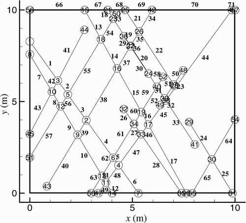
For simulating a two-dimensional (2D) DFN by the fractal concept, a square longitudinal section of 10 m × 10 m is considered. The jth with j = 1, 2, 3, …, j max fracture is defined by the centre position O j (x, y), the dip angle α j and the fracture length L j , where j max is the fracture total. Each fracture has two nodes, the jth fracture being between nodes i and i + 1. The node total is i max. The network discontinuity density is the reciprocal of the mean distance between the fractures. These are generally distributed uniformly in rock, the fracture centre O j (x, y) being defined by generating uniform random numbers between 0 and 1 in two directions. Natural fractures are commonly dipped in a preferred degree α j obeying the normal distribution, and the fracture length L j obeys a negative exponential distribution and the log-normal distribution. According to the specified ranges and the prototype distributions observed, α j and L j are sampled randomly in uniform random numbers between 0 and 1 using the inverse function method. If the density simulated agrees with the prototype data, the network simulation is finished. Applying the Monte-Carlo method, a 2D DFN was simulated using a FORTRAN program (, ). A joint matrix and a loop matrix explain the DFN.
Table 1 Statistical distribution of rock fracture characteristics
The correlation between fracture nodes and cells is defined as the joint matrix A = {a ij }
The basic loop within a fracture network is defined as loop matrix L = {L kj }
2.2 Automatic tracing of isolated rock block
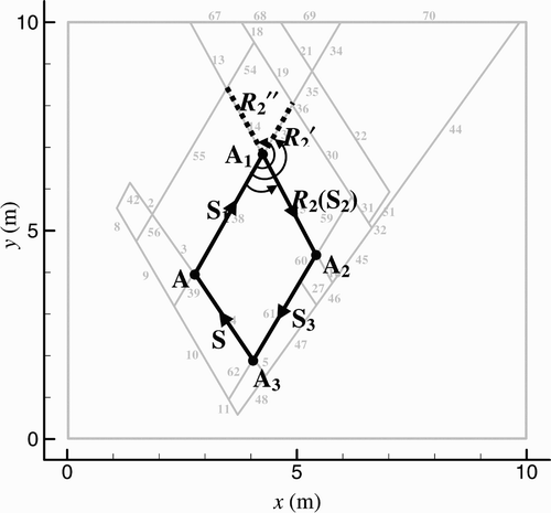
The automatic tracing of isolated rock block allows one to seek a basic loop within the rock mass ():
-
Chop tree: delete the cells that have no intersections or have only one with others;
-
Define clockwise as positive direction of each loop. Select S 1 as the basic cell and A 1 as the basic forward node;
-
Seek any other cells intersecting with S 1 at A 1, such as R 2, R 2′, R 2″ etc. Pick one that has the smallest anticlockwise angle from S 1 and mark it as S 2, and the forward node of S 2 is A 2;
-
Similarly, continue in circle until the loop is closed. Then the traced loop defines the smallest block within the rock mass.
When the key blocks on the surface are pulled up and taken away due to hydrodynamic pressure, other adjacent blocks are easily dislodged. After the surface damage, the new surface blocks are traced by applying the automatic tracing method of isolated blocks.
3 Numerical simulation of pressures propagation
3.1 Transient model
If a high-speed jet is discharged from a high arc dam, the upper rock boundary is exposed to intense pressure fluctuations. Based on the transient and wave characteristics of pressure propagation within slab joints, Fiorotto and Rinaldo (Citation1992a, Citation1992b) regarded the pressure propagation as a process of hydrodynamic transient. Liu and Li Citation(2007) discussed the model of pressure propagation and proposed the uniform transient model. Within the imitated fracture network, a 1D transient model was established along with each fracture cell as
Fiorotto and Rinaldo Citation(1990) observed that the drag effect determines pressure propagation for very narrow fractures. Liu and Li Citation(2007) discussed the drag term using theoretical analysis and numerical simulation, and deduced that the drag term significantly attenuates the high-frequency proportion of fluctuating pressures. Bollaert Citation(2002) proposed that the air entrained in the impinging jet may significantly reduce the propagation velocity and may lead to pressure resonance. All these effects complicate the problem. Because the main purpose herein is the methodological study of rock scour, the following assumptions are made:
-
Drag term effect on pressure transfer is neglected.
-
Influence of air entrained is not considered.
-
Propagating velocity of pressure wave is assumed a=1000 m/s.
-
Impinging jet is fully developed.
At the initial moment, t = 0, h = 0 and v = 0. The bottom boundary of the control volume is assumed impermeable, whereas the left and right boundaries are permeable. Under jet impingement, the severe fluctuating pressures acting on the upper boundary generally obey the normal distribution and have the low Eigen-frequency of less than 10 Hz (Cui Citation1986, Liu Citation1994, Liu and Li 2007). The second-order terms are neglected and the characteristic method is applied. The time step is Δt = 0.001 s, the spatial step is Δl = a · Δt = 1 m and the total calculating time is 10 s.
3.2 Distribution of fluctuating pressures
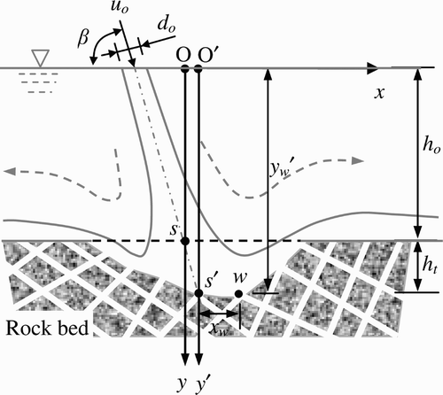
During impact of a water jet downstream of a high dam, the scour depth gradually increases. shows a sketch of the dynamic rock bed under jet impingement.
At a certain time, u o is the jet velocity, d o the jet thickness, β the jet impact angle, h o the water depth, h t the depth of scour hole and s the initial impinging point. At initial scour depth h o , the coordinates are (x, y) with the origin O. The intersection of the jet centreline and the dynamic rock bed is the dynamic impinging point s′. The vertical line from point s′ intersects the water surface at point O′, selected as the origin of the dynamic coordinate system (x, y′). The corresponding coordinates of any point w on the dynamic rock bed is (x w , y w ′).
The maximum pressure fluctuation and the time-averaged pressure are located close to the jet impact point. The root-mean-square (RMS) pressure fluctuation σ at s is (Cui et al. Citation1982)
As the scour depth increases, the energy carried in the jet is gradually dissipated in the scour pool. If y = y w , the RMS pressure fluctuation at point s′ is
And the correlation between the RMS of any points w and s′ is determined by
Using the specific parameter σ
s
, EquationEq. (10) can be normalized to
From EquationEqs (9) and Equation(11)
, the fluctuating pressure intensity at any point w of the dynamic rock bed decreases as h
0 and the relative distance X from s′ increase. To simulate pressure propagation within the imitated rock fracture network, the first fissure node from left to right on the initial rock plane is supposed to be s. The fluctuating pressure wave acting on w is therefore
3.3 Results of numerical simulation
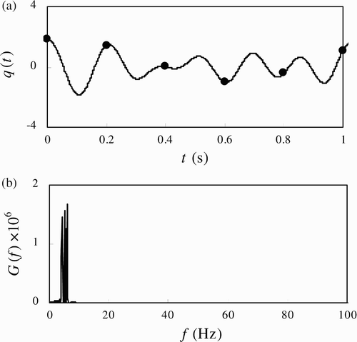
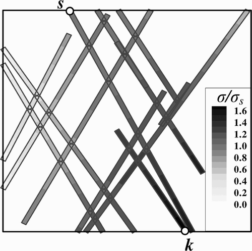
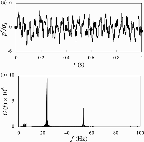
The temporal process and statistical characteristics of fluctuating pressures propagation within each fissure, and the special distribution of pressure intensity fluctuations are determined using numerical simulation. shows the spatial distribution of the relative RMS to σ s . shows the time process and the spectrum curve of point k marked in .
From and , it can be concluded that the fluctuating pressure propagation within the fracture network is a complex process. The pressure wave within any fracture differs from that at s is represented by q(t) (q(t) = p s ′/σ s ), made up of many high-frequency fluctuations. The fluctuating pressure of any node within the network is a summation of pressure waves propagated in it and the reflected waves from any other adjacent fissures. The reasons are as follows:
-
The fluctuating pressure propagation within the fracture network has typically anisotropic characteristics. The equivalent continuum models do not adapt to rock scour. Applying the fracture network explains more accurately this phenomenon.
-
The pressure fluctuations remarkably amplify within fissures. The computational results indicate that the maximum RMS within the fracture networks can reach up to 1.639σ s , whereas the maximum of p′ can reach 4.3σ s . Especially at the closed fissure ends, a concentrated zone of hydrodynamic stress occurs, promoting the fissured rock to be wedged by the jet and to be further fractured.
4 Mechanisms of rock disintegration and scour pool formation
4.1 Scour process
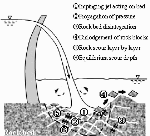
Under high-velocity jet impact, scouring is a physical process involving (1) impinging jet generating intense pressure fluctuations acting on fissured bed, (2) fluctuating pressures propagating rapidly within the fractures, (3) propagation of fissures into rock resulting in rock bed disintegration, Equation(4) isolated rock blocks vibrating randomly and being dislodged ultimately, (5) rock bed scour layer by layer and (6) scour pool reaching equilibrium depth (). The first two items were considered above and the others follow below.
4.2 Disintegration of rock bed
Based on the theory of spread and crash of fractures, the crash of rock bed mainly experiences two stages, i.e. generation and spread of fractures. Because many initial micro-fractures are involved in prototype rock, new fractures are generated as the water jet impacts a concentrated zone of alternative stress at the top fracture ends if the stress exceeds the limited intensity of rock crash. Simultaneously, the initial micro-fractures spread and develop rapidly along with their own crack line. Along with the continuous transfer of jet dynamic energy, the fractures then penetrate through the rock crystal boundaries spreading and intersecting gradually. Finally, the whole rock bed is composed of many cracked rock blocks of different dimensions and different shapes.
4.3 Dislodgement of isolated rock blocks
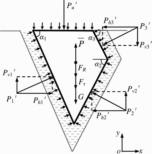
The float stability of rock blocks is one of the main criteria of rock scour damage. The forces acting on an isolated rock block include stable forces and uplift forces. The stable forces include gravity G = ρ r V r g, where V r is the rock volume, ρ r the rock density, where ρ r = 2.7∼2.8×10³ kg/m3 for the earth rock, shear resistant force F τ and the drag resistant force F R . The uplift forces include the fluctuating pressures within fractures P′, decomposed to vertical P v ′ and horizontal P h ′, the fluctuating pressure on the rock surface P u ′ and the time-averaged hydro-dynamic pressure ρV r g. These are all unit-width forces (). To assure vertical rock block stability,
For the block shown in , the fluctuating pressure P′ within fracture j is
Considering the three surrounding fracture cells (i.e. j = 1, 3), the dip angle α j , P v ′ and P h ′ for each cell, the resultant forces are
The fluctuating pressure P′ acting on the isolated block thus is
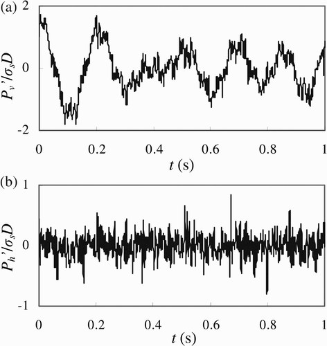
shows the time process curve of the vertical fluctuating pressure P v ′ and the horizontal fluctuating pressure P h ′ acting on a given block using σ s D, with D = (4S/π)0.5 = 1.23 m as the equivalent rock block diameter and S the rock area. It was observed that intense vertical fluctuating pressure promotes block dislodgement. The horizontal fluctuating pressure prompts the block being relaxed and shaken, which also promotes the dislodgement. Moreover, P u ′ is determined with the boundary conditions under jet impingement. Cui (1986) recommends P u ′ = ±3σ s . Assuming P v ′+P u ′ = f 1(σ s ), the stability criterion of rock block is
Once the function f 1(σ s ) is established via numerical simulation, the rock bed stability can be analysed quantitatively. For different blocks, the hydraulic conditions and the structural characters differ, and so the functions f 1(σ s ) are different too.
4.4 Rock scour layer by layer and equilibrium scour depth
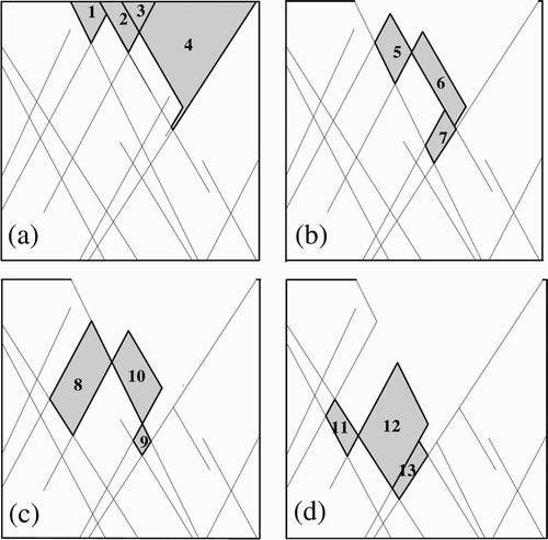
Rock scour is a process of isolated blocks dislodged layer by layer. If the surface isolated blocks do not meet the stability criterion after Eq. (19), they will be dislodged at a certain time resulting in a new surface. The dynamic characteristics and the stability of the isolated blocks on the new surface must then be re-analysed and repeated until all surface-isolated blocks meet the stability criterion and reach the equilibrium scour depth. shows the simulated dynamic rock bed at the first four damage stages.
Figure 10 Stages (a) I, (b) II, (c) III, Equation(4) IV
5 Scour prediction of Xi Luo Du hydro-electric plant
The Xi Luo Du hydro-electric power plant is located at the Jing Sha River in China. The rock scour downstream of the high-arc dam is simulated below, introducing the DFN as follows:
-
Based on site data in Cave D07 (), DFN is imitated from 70 to190 m downstream from the dam toe, reaching a depth of 100 m.
-
Two fracture groups are uniformly distributed with the density of 0.8 m−1. Assume the rock bed totally cracked, and the mean length and thickness of fractures are 100 m and 2 mm, respectively.
-
The up- and downstream boundaries are permeable whereas the bottom is impermeable. The site conditions are listed in .
Table 2 Statistics of rock fractures on right bank
Table 3 Overflow conditions of #5 surface opening
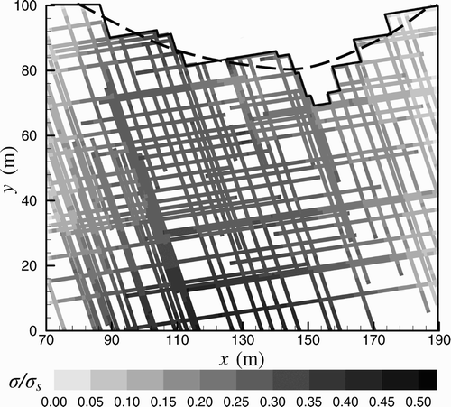
shows the numerical result of the equilibrium scour pool by a real line and the spatial distribution of the relative RMS to σ s , the mean scour curve is also given by the dotted line. For these conditions, the ultimate scour depth is about 31 m, and the scour pool is stretched downstream about 104 m (from 86 to 190 m).
The Monte-Carlo method is a random statistical method. Three different networks were simulated in addition to calculation of the mean value of maximum scour depth. compares the scour depth predictions with other (semi-)empirical formulations. Obviously, the predicted results by numerical simulation using DFN compare well with the (semi-)empirical results.
Table 4 Prediction comparison of equilibrium scour depth
6 Conclusions
Scour of rock bed is a sequential dynamic process of rock being disorganized, fragmentized and dislodged. During rock scour, the jet flow character, the structure of rock mass and the stress state within the network are all changed momentarily. It is obviously deficient to study pressure propagation, which has typical anisotropic character, based on the static theory and the equivalent continuum models. A complex rock fracture network was introduced herein to simulate the rock scour process. The main conclusions include:
-
Through numerical simulation of pressure propagation within DFN, the development of the scour hole is described quantitatively and visually. The scour hole shape, depth and the spatial distribution of pressure fluctuations within rock fissures at each stage are obtained.
-
The general model of rock scour, i.e. jet impinging, propagation of fluctuating pressures, rock disintegration, isolated rock dislodgement, layer by layer rock bed scour, and equilibrium scour depth, is described.
-
Applying numerical simulation to predict rock scour downstream of Xi Luo Du hydro-electric power plant provides reasonable simulation results.
Notation
| A | = |
joint matrix |
| a | = |
propagating velocity |
| f | = |
frequency of fluctuating pressure |
| g | = |
acceleration due to gravity |
| h | = |
head of fluctuating pressure |
| h t | = |
scour depth |
| h tm | = |
maximum scour depth |
| i | = |
number index of fracture node |
| j | = |
number index of fracture cell |
| k | = |
index of network loop |
| L | = |
loop matrix |
| L j | = |
length of fracture cell j |
| p¯ | = |
time-averaged pressure |
| p′ | = |
fluctuating pressure |
| s | = |
jet impact point |
| α j | = |
dip angle of fracture cell j |
| γ | = |
specific weight of water |
| δ | = |
thickness of fissure |
| λ | = |
dimensionless joint blockage coefficient |
| ρ | = |
water density |
| ρ r | = |
rock density |
| σ | = |
standard deviation of pressure fluctuation |
Acknowledgements
This research has been financially supported by the National Natural Science Foundation of China, Grants Nos. 10772015 and 50539060.
References
- Annandale , G. W. 2006 . Scour technology , New York : McGraw-Hill .
- Bellin , A. and Fiorotto , V. 1995 . Direct dynamic force measurement on slabs in spillway stilling basins . J. Hydraul. Eng. , 121 ( 10 ) : 686 – 693 .
- Bollaert , E. 2002 . “ The influence of plunge pool air entrainment on the presence of free air in rock joints ” . In Rock Scour Due to High-velocity Jets , 137 – 149 . Switzerland : EPFL Lausanne . Proc. Intl. Workshop
- Bollaert , E. and Schleiss , A. 2003 . Scour of rock due to the impact of plunging high velocity jets 1: Experimental results of dynamic pressures at pool bottoms and in one- and two-dimensional closed end rock joints . J. Hydraulic Res. , 41 ( 5 ) : 465 – 480 .
- Bollaert , E. and Schleiss , A. 2005 . Physically-based model for evaluation of rock scour due to high velocity jet impact . J. Hydraul. Eng. , 131 ( 3 ) : 153 – 165 .
- Bowers , C. E. and Toso , J. 1988 . Karnafuli project, model studies of spillway damage . J. Hydraul. Eng. , 114 ( 5 ) : 469 – 483 .
- Chen , J. P. 2001 . 3-D network numerical modeling technique for random discontinuities of rock mass . J. Geotech. Eng. , 23 ( 4 ) : 397 – 402 . [in Chinese]
- Cui , G. T. Discussion of the maximum breadth of water fluctuating pressure . 2nd Congressional Corpus . Beijing. Information net of high-speed flow , China 10, 84–88, [in Chinese]
- Cui , G. T. , Lu , R. G. and Lin , J. Y. 1982 . Discussion to dynamic pressures due to ski-jump jet and protection of rock bed . J. Tian Univ. , 2 : 23 – 26 . [in Chinese]
- Fiorotto , V. and Rinaldo , A. 1990 . Discussion to Karnafuli project, model studies of spillway damage . J. Hydraul. Eng. , 116 ( 6 ) : 850 – 852 .
- Fiorotto , V. and Rinaldo , A. 1992a . Fluctuating uplift and lining design in spillway stilling basins . J. Hydraul. Eng. , 118 ( 4 ) : 578 – 596 .
- Fiorotto , V. and Rinaldo , A. 1992b . Turbulent pressure fluctuations under hydraulic jumps . J. Hydraulic Res. , 30 ( 4 ) : 499 – 520 .
- Hammersley , J. M. and Handsconmb , S. C. 1964 . Monte-Carlo method , London : Methuen .
- Hanson , G. J. , Robinson , K. M. and Cook , K. R. Erosion of structured material due to impinging jet . Proc. Intl. Water Resources Engineering Conference . Memphis, TN. pp. 1102 – 1107 . ASCE, New York
- Johnson , G. M. Use of a weakly cohesive material for scale model scour studies in flood spillway design . 17th IAHR Congress . Baden-Baden. pp. 509 – 512 . 4(C63)
- Liu , P. Q. 1994 . “ Mechanism of free jet's scour on rocky river-beds ” . In PhD thesis , Beijing, , China : Higher Education Press . [in Chinese]
- Liu , P. Q. and Li , A. H. 2007 . Model discussion of pressure fluctuations propagation within lining slab joints in stilling basins . J. Hydraul. Eng. , 133 ( 6 ) : 618 – 624 .
- Manso , P. A. 2006 . “ The influence of pool geometry and induced flow patterns on rock scour by high-velocity plunging jets ” . In PhD thesis EPFL, Lausanne, 3430
- Mason , P. J. and Arumugam , K. 1985 . Free jet scour below dams and flip buckets . J. Hydraul. Eng. , 111 ( 2 ) : 220 – 235 .
- Ouenes , A. 2000 . Practical application of fuzzy logic and neural networks to fractured reservoir characterization . Comput. Geosci. , 26 ( 8 ) : 953 – 962 .
- Stein , O. R. , Julien , P. Y. and Alonso , C. V. 1993 . Mechanics of jet scour downstream of a headcut . J. Hydraulic Res. , 31 ( 6 ) : 723 – 738 .
