Abstract
A finite-volume model was built upon earlier work with the aim of simulating free surface flows, pressurized flows and their simultaneous occurrence (mixed flows) in single-liquid and two-phase flow conditions (entrapment and release of air pockets). The model presented herein is based on a two-governing equation model. Three main contributions are presented herein, namely (1) the ability of the proposed model to simulate mixed flows without restriction of the flow type in the free surface region (e.g. supercritical flow), (2) extension of our single-phase flow model for simulating the entrapment and release of air pockets and (3) formulation of an approach for handling numerical instabilities that may occur during numerical pressurization of the flow. The model presented herein is robust and simulates any transient-mixed flow condition for realistic pressure wave celerities.
1 Introduction
The simultaneous occurrence of free surface and pressurized flows (mixed flows) is simulated using one or two sets of governing equations (e.g. Capart et al. Citation1997, Trajkovic et al. Citation1999, León Citation2006, Vasconcelos et al. Citation2006, Politano et al. Citation2007, León et al. Citation2009). Mixed flow models that use only the single set of the Saint-Venant equations require an approximation for simulating pressurized flows. The most common approximation is the well-known Preissmann slot, which consists of a hypothetical narrow open-slot on top of the conduit (Capart et al. Citation1997, Trajkovic et al. Citation1999). The main limitation of this model is its inability to simulate sub-atmospheric pressures in pressurized flow conditions. To overcome this limitation, Vasconcelos et al. Citation(2006) modified the Saint-Venant equations to allow for over-pressurization, assuming that elastic behaviour of the pipe walls will account for the gain in pipe storage. The main limitation of this approach is the presence of what these authors call “post-shock oscillations” near open-channel-pressurized flow interfaces. To keep these oscillations small, lower values for the pressure wave celerity may be used, yet this may compromise the simulation accuracy if pressurized transients are simulated. It is cautioned that numerical oscillations may produce unrealistic negative pressures and pollute the numerical solution.
Mixed flow models that are based on a one single set of governing equations use small values of the pressure wave celerity to avoid numerical instabilities (Trajkovic et al. Citation1999, Vasconcelos et al. Citation2006). Good results are obtained when simulating mixed flows in a single pipe, in which the pressurized flow region is isolated and there is no interaction of pressurized waves (Trajkovic et al. Citation1999, Vasconcelos et al. Citation2006, León et al. Citation2009). However, as shown by León et al. Citation(2010), if there is interaction of pressurized waves, such as in multiple pipe flow, the results highly depend on the selection of the pressure wave celerity. As discussed by León and Ghidaoui Citation(2010), numerical oscillations in pipe filling bores can be minimized for realistic wavespeeds (e.g. ∼1000 m/s) by choosing governing equations that best mimic the physics. The flow regime on one side of the filling bore is pressurized flow, while that on the other side is free surface flow. Hence, an appropriate approach enforces the water hammer equations in the pressurized region, the Saint-Venant equations in the free surface region and the jump relations across the filling bore.
Among the approaches for simulating mixed flows (single-phase flows), finite-volume (FV) shock-capturing methods, in particular Godunov-type schemes, are gaining popularity for their ability to capture shocks in the solution automatically, without explicitly tracking them (Nujic Citation1995, Sanders Citation2001, Toro Citation2001). These schemes were applied to the Saint-Venant equations and the two governing equations (Saint-Venant equations and compressible water hammer equations). As mentioned earlier, a two-governing equation model must be used for simulating complex closed-conduit systems for transient-mixed flows with a pressure wave celerity of ∼1000 m/s. Regarding single-phase mixed flow models based on the application of FV schemes to both the Saint-Venant equations and the compressible water hammer equations (two sets of governing equations), the present authors are aware of only two FV models, namely these of León Citation(2006) and of Bourdarias and Gerbi Citation(2007). León Citation(2006) presented a shock-tracking-capturing method, in which open-channel-pressurized flow interfaces are tracked, introducing or merging cells as the interfaces propagate in the pipe. The compatibility conditions are enforced across open-channel-pressurized flow interfaces, and a shock-capturing approach is used in pure free surface and pressurized flows.
Bourdarias and Gerbi Citation(2007) presented a shock-capturing approach for simulating mixed flows, in which the governing equations for free surface and pressurized flows were linearized. For a positive open-channel-pressurized flow interface, the mass and momentum compatibility conditions were enforced across the mixed flow interface together with the Rankine–Hugoniot mass conservation condition across a linearized wave in the pressurized flow region. For negative interfaces, besides the equations used for positive interfaces, the energy equation was enforced across the interface and a linearized open-channel flow Riemann problem was solved using the well-known linearized Riemann solver (Toro Citation2001, León et al. Citation2006, León Citation2006). Song et al. Citation(1983) defined an open-channel-pressurized (mixed) flow interface as positive if it is moving towards the open-channel flow (), and negative if it is moving towards the region of pressurized flow (). The directional interface change from positive to negative is called interface reversal (). Bourdarias and Gerbi Citation(2007) also used the linearized Riemann solver for computing the flow variables in the free surface and pressurized flow regions. As pointed out by Toro Citation(2001), the linearized Riemann solver for free surface flows is not sufficiently robust to be generally used. In particular, this solver may give negative depths in cases involving strong rarefactions leading to very shallow water. Furthermore, the approach proposed by Bourdarias and Gerbi Citation(2007) for negative interfaces (mixed flow) was formulated only for sub-critical free surface flow. Thus, a model is desired with capabilities of simulating mixed flows without restriction of flow type in the free surface region (e.g. supercritical flow).
Figure 1 (a) Positive interface moving in upstream direction, (b) negative interface moving in upstream direction, (c) interface reversal
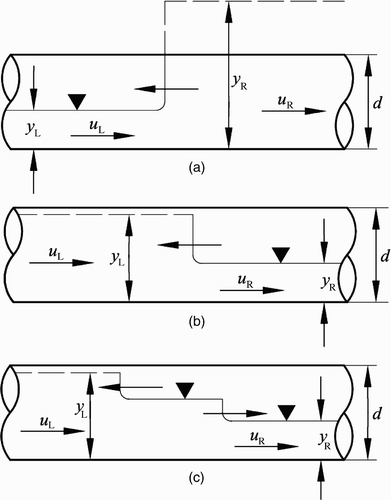
When using a two-governing equation model and simulating a pure free surface flow that is about to get pressurized, numerical instabilities, which may lead to program abortion, may occur, especially if pipe filling is slow. Numerical instabilities occur because of singularities in the equations for numerical pressurization of the flow. For instance, the wave speed of a mixed flow interface is singular at the threshold for changes from free surface to pressurized flow. If the piezometric heads of the free surface and the pressurized flows are similar, numerical instabilities may occur. These instability problems are increased due to the precision of the computer used. The lower the precision used, the more the instability problems are attained. To make a model robust, the instability problems due to numerical flow pressurization need to be addressed.
With regard to two-phase flow models (entrapment and release of air pockets) based on the application of FV schemes to both the Saint-Venant equations and the compressible water hammer equations, no model appears to be currently available. This work is organized as follows: Equation(1) governing equations for single- and two-phase flow conditions are provided, Equation(2)
numerical solution of mixed flow interfaces is presented, Equation(3)
threshold levels for piezometric depths during numerical pressurization is presented, Equation(4)
accuracy and robustness of the proposed model are evaluated using experimental literature data and Equation(5)
results are summarized.
2 Mathematical description
2.1 Governing equations for free surface and pressurized flows
The governing equations used herein are identical to those of León Citation(2006) for single-phase flows, except for the air phase. In the single-phase flow model, the free surface region is simulated using the 1D Saint-Venant equations and the pressurized region is simulated using the 1D compressible water hammer equations. The inclusion of the air phase in the Saint-Venant equations is similar to the approach used by Arai and Yamamoto Citation(2003), and Vasconcelos Citation(2005). These equations are
For compressible water hammer flows, these are (Guinot Citation2003, León Citation2006, León et al. Citation2008)
Equation Equation(1) for compressible water hammer flows does not form a closed system because the flow is described using the three variables ρ
f
, p and Q but only two equations are available. To close this system, the following equation relating p and ρ
f
is used (León et al.
Citation2007, Citation2008):
2.2 No air release
Considering an isolated air pocket, the ideal gas law with the assumption of an isentropic process gives (e.g. Martin Citation1976)
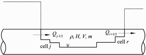
For a confined air pocket with no air release, EquationEq. (5) can be used to compute H required to estimate F in EquationEq. (2)
. To determine H, the volumetric change of an air pocket with time dV/dt needs to be determined. It is computed using the net flow discharge flux evaluated at the air pocket boundary as ()
Note from that the fluxes at cell interfaces inside the air pocket other than the boundaries cancel each other. Previous approaches used the speed of open-channel-pressurized flow interfaces surrounding an air pocket for computing dV/dt (Wang et al.
Citation2003, Vasconcelos Citation2005). Tests with the proposed model using the latter approach lead to numerical oscillations and eventually the abortion of the program. These oscillations are caused by the extremely sensitive speed of the interface that changes rapidly, especially in fast pipe filling scenarios. Conversely, the approach of computing dV/dt using EquationEq. (6) leads to a robust model virtually free of numerical oscillations. If EquationEq. (6)
is used, numerical instabilities may still be present due to other reasons such as the numerical scheme used for solving the governing equations; however, the instabilities due to air volume computation are reduced. For computing air density, the air pocket volume at the new time step is updated as V
n+1 = V
n
+ dt(dV/dt). The new air density is computed using this new air pocket volume.
2.3 With air release
Considering air release, EquationEq. (5) can be modified to take into account the air flow discharge out of an air pocket. This new relation is (Martin Citation1976, Zhou Citation2000)
If H*/H b * > 1.89, the orifice is choked and (Martin Citation1976)
For the case of air release, dV/dt can be computed in the same way as for no air release. For computing air density, the mass of air inside the air pocket at the new time step is updated according to the air flow discharge. The new air density is computed using this new air mass and the new air pocket volume.
Free surface flow tests in circular pipes (Hamam and McCorquodale Citation1982) demonstrated that flow instabilities occur for piezometric depths greater than 0.8d, causing oscillations that lead with a sudden jump to pressurized flow. As mentioned earlier, the phase change from free surface to pressurized flow (not from pressurized to free surface flow) is assumed to occur if the piezometric depth exceeds y = y ref , where y is the piezometric depth and y ref the reference depth. Herein, y ref = 0.95d. Note that the results are not significantly sensitive to y ref . However, when using a small value of y ref , large mass conservation errors may occur. The reference area A ref is the hydraulic area below y ref = 0.95d and A f in the previous equations is replaced with A ref . This results in a reduction of the hydraulic area for pressurized flows of less than 2%. If using the present model to simulate pure pressurized flows, A ref can be set equal to A f . The reduction in hydraulic area for pressurized flows of less than 2% is then eliminated. For the phase change from pressurized to free surface flow, the criterion of Yuan Citation(1984) is used.
The above-presented governing equations relate to free surface and pressurized flows. Consider now an interface between free surface and pressurized flow regions moving with a speed w. The weak form of EquationEq. (1) is (Toro Citation2001)
The flow variables used herein are (ρ w A) and (ρ w Q) for free surface flows, and (ρ f A f) and (ρ f Q f ) for pressurized flows. However, the engineering community prefers to use the piezometric head h and discharge Q. The latter variables can be determined from the flow variables as
-
Free surface flow
-
Pressurized flow
After a given node has been pressurized, free surface flow is not necessarily generated at this node if its head drops below the pipe crown. As reported by Cardle Citation(1984), Yuan Citation(1984) or Cardle et al. Citation(1989), there is a negative pressure on the pressurized side of the interface in negative interfaces. The latter implies that if a pipe system has been fully pressurized, the only way to start the depressurization process is through ventilated boundaries by dropshafts or reservoirs (e.g. Cardle Citation1984).
3 Numerical solution of mixed flow interfaces
3.1 Overview
A part of our model for simulating only mixed flows is presented. For pure free surface and pressurized single-phase flows, the reader is referred to León Citation(2006) and León et al. (Citation2006, Citation2008). A mixed flow is composed of one region in free surface flow and another adjacent in pressurized flow conditions. The numerical scheme used for updating the solution from one time step to the next for mixed flows is the same as presented by León Citation(2006) and León et al. (Citation2006, Citation2008) for free surface and pressurized flows. This scheme is an explicit FV method first-order accurate near shocks and discontinuities and second-order accurate away from discontinuities. When using the FV scheme, to update the flow variables U at cell “i” from a time step to the next the numerical flux F at the cell interfaces i − 1/2 and i + 1/2 needs to be estimated. For computing vector F in EquationEq. (2) or Equation(3)
, the flow variables at the cell interface [(ρA)
i+1/2 and (ρQ)
i+1/2] need to be estimated. This section focuses on the computation of these if the flow regimes at the sides of the cell interface i + 1/2 are different. If the flow regime changes across the cell interface, it is named herein mixed flow interface. The approach used herein for estimating the flow variables is similar to that used by Song et al.
Citation(1983), Cardle Citation(1984), Cardle and Song Citation(1988) or Bourdarias and Gerbi Citation(2007). Note that the treatment of boundary conditions is not presented herein due to space limitations. The reader is referred to León et al.
Citation(2010).
3.2 Positive interface propagating upstream
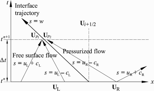
In this case, a mixed flow interface is moving upstream towards the open-channel flow region. The treatment for such a positive interface propagating downstream is identical to this case but will not be presented. The flow across a positive interface is equivalent to a flow across a hydraulic bore or, in compressible gas flow, a shock, which means that the flow changes from supercritical or supersonic to sub-critical or subsonic flow as it moves in relative coordinates (Cardle Citation1984). A classical statement in hydraulics used in the video “Waves in fluids” (Bryson Citation1964) reads: “A disturbance behind a shock moving towards the shock interface catches up with it and disturbances in front of the shock are overtaken by it”. This statement is simply that the Froude (Mach) number behind a shock <1 and ahead of it >1. By making use of this classical statement, the x−t diagram for a positive interface having sub-critical flow in the free surface region was constructed (), similar to the diagram of Song et al. Citation(1983), or Cardle and Song Citation(1988).
Recall that the flow variables at the cell interface i + 1/2 at time t
n+1
are sought to compute the fluxes at this interface. In , the flow variables at left and right of the cell interface i + 1/2 at time t
n+1 are
and
, respectively. Because a shock-capturing approach is used, the location of the moving mixed flow interface and that of the cell interface separating the free surface and pressurized flow cells (fixed grid) are identical at time t
n
. The flow variables at i + 1/2 and time t
n
are
and
, respectively. These flow variables at time t
n
are already known from the previous time step computations. To estimate
, only
need to be determined because
. However,
is related to
and w
n+1. Thus, to determine
, the five variables
,
,
,
and w
n+1 need to be estimated. The number of variables needed can be reduced in two as is shown next.
The application of the concept of Riemann invariants along the characteristics u L+c L and u L−c i in , respectively, gives (León et al. Citation2006)
In the system of EquationEqs (16),
and
. Because
, only the three variables
,
and w
n+1 are needed to determine
. Since three equations are required the equations of conservation of mass, momentum and energy across the mixed flow interface can be used. However, from , p
2 and R are connected by the characteristic u
R−c
R and therefore, one equation must relate p
2 to R. Because it is difficult to quantify the energy losses in the conservation of energy equation, the equations of conservation of mass and momentum are used, namely EquationEqs (12)
and Equation(13)
, where subscripts L and R must be replaced by p
1 and p
2, respectively (). To obtain the third equation, the concept of Riemann invariants is enforced along the characteristic s = u
R − c
R (), which gives
To reduce the number of equations by one, w was eliminated from EquationEqs. (12) and Equation(13)
. For solving the resulting two equations, the Newton–Raphson method for nonlinear systems of equations was used. When implementing this approach for actual storm-sewer systems, the Newton–Raphson method may not always converge. In those cases, a set of adaptive and more robust solvers such as HOMPACK or MINPACK may be needed. Having thus determined
and therefore
, the flux at the cell interface i + 1/2 can be determined using the flux vector term in EquationEq. (3)
.
For a supercritical free surface flow moving in the downstream direction, the concept of Riemann invariants along the characteristics u
L+c
L and u
L−c
L in can still be applied and as for sub-critical flows . The latter means that for a positive interface, the flux at the cell interface does not depend on the flow type in the free surface region.
3.3 Negative interface propagating upstream
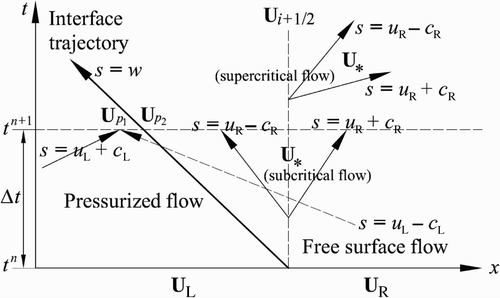
In this case, a negative mixed flow interface is moving upstream toward the pressurized flow region (). The treatment for a negative interface propagating downstream is identical and will not be presented. It is noted from ) that the propagation of a negative interface results in the depressurization of the pressurized region. However, as mentioned earlier, depressurization does not occur if the piezometric head on the pressurized region drops below the pipe crown (Cardle Citation1984, Yuan Citation1984, Cardle et al. Citation1989), but if the piezometric depth drops below a threshold value. For circular conduits, this is about 0.84d (Yuan Citation1984). Notice that the threshold value for depressurization is different to that of pressurization. Herein the pressurization of the free surface region is assumed to occur if the piezometric head exceeds y = y ref .
In a similar way to the case of a positive interface, the x−t diagram for a negative interface propagating upstream is shown in . Notice that the negative mixed flow interface overtakes the pressurized flow waves and that the free surface flow waves do not interact at all with the negative interface. These characteristics of a negative interface are different to those of a positive interface (shock-wave).
A reader familiar with the solution of a Riemann problem can notice from that to estimate , only
needs to be determined. The reason is that if
is known, an open-channel flow Riemann problem can be solved to estimate
using as left, intermediate and right states, U
p2, U
*
(star region) and U
R, respectively (e.g. Toro Citation2001, León et al.
Citation2006). However,
is related to
and w
n+1. Thus, five variables
need to be determined, and naturally five equations are required to determine these variables. In a way similar to the positive interface, the first two equations are obtained by enforcing the conservation of mass and momentum across the negative interface (Eqs 12 and 13), where subscripts L and R must be replaced by p
1 and p
2, respectively.
Note from that the concept of Riemann invariants can be enforced only along the characteristic s = u L + c L. The characteristics s = u R−c R and s = u R + c R do not connect p 2 and R, and the characteristic s = u L − c L cuts the mixed flow interface, and therefore the concept of Riemann invariants cannot be enforced along these characteristics. Thus, for a negative interface, only one extra equation is obtained with this concept along the characteristic s = u L + c L. This third equation is given by
The derivation of EquationEq. (19) is similar to that presented in Appendix 1 by León et al.
Citation(2006) using the constant a instead of c. Experimental results show that the speed of a positive and negative interfaces is nearly constant (e.g. Cardle Citation1984, Cardle et al.
Citation1989). Thus it is common to estimate the interface speed w at time n+1 using flow variables at the previous time step n (Song et al.
Citation1983, Cardle and Song Citation1988). Since w
n+1 is computed explicitly, only four variables
need to be determined and consequently, only one more equation is needed.
The energy equation across the interface was finally used as (Cardle Citation1984, Yuan Citation1984, Cardle and Song Citation1988, Bourdarias and Gerbi Citation2007)
To show that the HLL solver effectively handles supercritical flows, consider, for instance, that the flow at the right of the mixed flow interface in is supercritical moving to the right. In this case, is equal to
(), so that the flow variables at the cell interface x
i+1/2 are determined. Having thus determined
, the flux at the interface i + 1/2 is determined using the flux vector term in EquationEq. (2)
(free surface flows). If the flow at the right of the mixed flow interface in is sub-critical, the flow variables in the intermediate region between the characteristics s = u
R − c
R and s = u
R + c
R need to be determined. The reader is referred to León et al.
Citation(2006) for the HLL method applied to circular conduits. Unlike other mixed flow models that were not formulated for negative interfaces, if the flow in the free surface region is supercritical (Cardle Citation1984, Yuan Citation1984, Cardle and Song Citation1988, Bourdarias and Gerbi Citation2007), the proposed approach is able to simulate negative interfaces without restriction to the flow type in the free surface region.
4 Threshold levels for piezometric depths
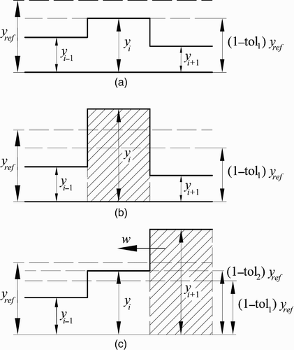
As mentioned in Section 1, when using a two-governing equation model and if simulating a pure free surface flow that is about to get pressurized, numerical instabilities, which may lead to program abortion, may occur, especially if pipe filling is slow. To overcome the numerical instabilities that may be produced during numerical pressurization (y = y ref ), two threshold levels are defined. These are y = (1−tol1)y ref and y = (1−tol2)y ref subjected to
For illustrating the use of the two defined threshold levels, three cases, which are depicted in )–(c), are presented herein. For the first case illustrated in ), the flows at the old time step t n in cell i and its adjacent cells i − 1 and i + 1 are in free surface regime. If, after updating the solution to cell i for t n+1, the piezometric depth in this cell falls between (1−tol1)y ref and y ref , the flow in cell i at the new time step t n+1 remains in free surface flow conditions with a piezometric depth equal to y = (1−tol1)y ref . For the second case illustrated in ), the flow at old time step t n in cell i and its adjacent cells i − 1 and i + 1 are identical as in the first case. If, after updating the solution at cell i for t n+1, the piezometric head exceeds y ref , and cell i at t n+1 is assumed to be pressurized (shaded region in ). The third case, shown in ), corresponds to the pressurization of cell i adjacent to the positive interface (i + 1/2). The flows at old time time step t n in cells i and i + 1 are in free surface and pressurized regime, respectively, and the positive interface i + 1/2 is traveling to the left. Note that cell i (free surface flow conditions) may get pressurized due to the flow advected by the positive interface so that it may seem obvious that no constraint should be specified for the pressurization of this cell. However, if the piezometric head in cells i (y < y ref ) and cell i+1 (y > y ref ) are similar, it may lead to numerical instabilities. Thus, if the piezometric head in cell i falls between (1−tol2)y ref and y ref , the flow in cell i at the new time step t n+1 remains in free surface flow conditions with a piezometric head equal to y = (1−tol2)y ref . Because tol2 is very small, the constraint imposed does not affect significantly the accuracy of the results. As in the second case, if the piezometric head exceeds y ref , the cell i at t n+1 is assumed to be pressurized.
An approach similar to that presented for numerical pressurization can be implemented for numerical depressurization. However, in all the simulations performed, no numerical instabilities associated to cell depressurization were experienced.
5 Evaluation of model
The purpose of this section is to evaluate the accuracy and robustness of the proposed model to simulate transient-mixed flows in storm-sewers in single (pure liquid) and two-phase flow conditions (entrapment and release of air pockets). Four test cases are considered in this section. These are as follows:
-
Experiments (type A) of Trajkovic et al. Citation(1999) (single-phase mixed flow).
-
Experiment of Vasconcelos et al. Citation(2006) (single-phase pressurized flow).
-
Experiments of Zhou Citation(2000) (air pocket entrapment with no air release).
-
Experiments of Zhou Citation(2000) (air pocket entrapment with air release).
5.1 Experiments of Trajkovic
Herein, the proposed model is used to reproduce a set of experiments conducted at the Hydraulics Laboratory, University of Calabria, by Trajkovic et al. Citation(1999). The ability of the proposed model is tested to simulate a positive mixed flow interface (single-phase) reversing its direction and becoming a negative interface. The test setup consisted of a perspex pipe about 10 m long, having an inner diameter of 10 cm and a Manning roughness coefficient n = 0.008 m1/6 (Yen Citation1991). The initial conditions for this test were a constant discharge of 0.0013 m3/s, S o = 2.7% resulting in supercritical flow with an approach flow Froude number of F = [u/(gh)1/2] = 2.9, an upstream sluice gate opening of e 1 = 0.014 m and the downstream sluice gate totally opened. The transient flow was generated after a rapid but not instantaneous closure of the downstream sluice gate causing the formation of an open-channel surge moving upstream. This surge was continuously strengthened by the inflow and after few seconds became a positive mixed flow interface moving upstream. After 30 s from gate closure, the gate was partially reopened. Different reopening values e 2 were tested. Herein, the three values e 2 = 0.008 m, e 2 = 0.015 m and e 2 = 0.028 m are considered.
Simulated (proposed and from Trajkovic et al.'s (1999) model) and measured pressure heads 0.6 m from the downstream gate for the three reopenings are shown in . The results for the proposed model were generated using 400 cells, a Courant number of C = [(u+c)Δt/Δx for free surface flow or (u+a)Δt/Δx for pressurized flow] = 0.80 and a = 500 m/s. The results of Trajkovic et al.'s model were generated using a pressure wave celerity of about 4 m/s. Even though the comparison of results between our model and that of Trajkovic et al. Citation(1999) may not seem relevant because different pressure wave celerities were used, the results indicate that our model is robust for large pressure wave celerities.
Figure 6 Measured and computed piezometric depths 0.6 m from downstream gate for type A tests of Trajkovic et al. Citation(1999) for different reopenings
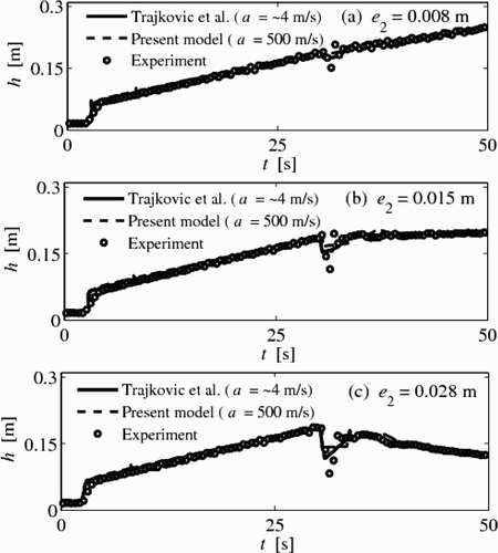
As can be observed from , the simulated piezometric head h for both numerical models have a good agreement with the corresponding tests measurements. In particular, the formation of the filling bore and its propagation velocity are accurately predicted. However, all the computed shock fronts are steeper than those measured, because of rapid gate closure, yet not instantaneous, as assumed in the simulations. also shows a drop in the piezometric head after the partial reopening of the downstream gate at t = 30 s. In both simulations, an instantaneous partial reopening was assumed, which caused a steeper front of the pressure drop as compared with the experimental results. The smaller pressure drop in both simulations may be in part due to the inaccuracies in representing the partial opening at the downstream boundary, where the orifice equation of Trajkovic et al. Citation(1999) was used.
For a reopening of 0.008 m (), after a small drop in the piezometric head, it continuously increased in both models and the test. This is because the pipe outflow was smaller than the inflow. For a reopening of 0.015 m (), a steady mixed flow interface was observed and computed for the test and proposed model in the pipe after the drop in piezometric head. For a reopening of 0.028 m (), the mixed flow interface travelled downstream for the test and the proposed model, because the outflow was larger than the inflow. It is acknowledged that the numerical results of Trajkovic et al. Citation(1999) for a reopening of 0.015 and 0.028 m (,c) are not shown after about t = 32 s (shortly after partial gate reopening). Numerical instabilities were reported by Trajkovic et al. Citation(1999) even though a small wave celerity of ∼4 m/s was used.
According to Trajkovic et al. Citation(1999), Vasconcelos et al. Citation(2006) or León et al. Citation(2009), the results are almost independent of the pressure wave celerity when simulating mixed flows in a single pipe, in which the pressurized flow region is isolated and if there is no interaction of pressurized waves. This explains why researchers, using very low pressure wave celerities, obtained good agreement with tests when simulating mixed flows. However, as demonstrated by León et al. Citation(2010), the results depend significantly on the selection of the pressure wave celerity if there is an interaction of pressurized waves such as in multiple pipes. In the latter case, only a pressure wave celerity equal to the water hammer wavespeed gives accurate results of the frequency and magnitude of pressurized transients.
From ) and ), it can be noted that shortly after the gate was reopened to 0.015 or 0.028 m, the positive interface reversed its direction, becoming a negative interface. This is particularly evident for a reopening of 0.028 m (). Also, the initial Froude number was about 2.9, corresponding to supercritical flow. As mentioned earlier, one of the present contributions is that the proposed model can simulate mixed flows without restriction of the flow type in the free surface region. ) and ) demonstrates that our model simulates a negative interface for supercritical flow in the free surface region.
5.2 Experiments of Vasconcelos et al.
The purpose of this section is to test the ability of the proposed model to simulate sub-atmospheric pressures in pressurized flow regime (single-phase). The test considered was conducted at the University of Michigan and is reported by Vasconcelos et al. Citation(2006). The setup consisted of an acrylic pipeline of 14.33 m long and 9.4 cm inner diameter. Its centre portion was raised about 15 cm with respect to both ends to create conditions for the occurrence of sub-atmospheric pressures. The pipeline was connected at its upstream end by a box tank and by a cylindrical tank at its downstream end. The test considered was obtained by filling the system to a level of 0.30 m at the box tank and the system allowed to come to rest. Then a syphon outflow was suddenly initiated at the box tank at t = 0. The water level in the box tank then decreased to a level that created sub-atmospheric pressures at the pipe centre portion. As the water level in the box tank dropped below the pipe crown just downstream of this tank, a complex flow pattern was developed. The flow just downstream of the box tank was then in sub-atmospheric conditions, and air flowed from the tank into the pipe. This constitutes a two-phase flow problem, which is outside the present scope. The intrusion of air flow in the test occurred at about t = 42.5 s, and in the model about 1.7 s earlier. Since this work is limited to single-phase flows, the comparison between model prediction and test results is only presented until just before the occurrence of air intrusion (t< ≈ 40.8 s).
If the present model is used to simulate fully pressurized flows, as in this test case, A ref = A f . Then, the 2% reduction in hydraulic area for pressurized flows assumed for mixed flow conditions is eliminated. The pressure wave celerity used in the simulations was 300 m/s based on test measurements. The outflow was assumed constant at 0.45 l/s by observing the change in water volume over time. For estimating energy losses, Vasconcelos et al. Citation(2006) used 0.012 m1/6. However, Manning's equation is only applicable to fully rough flows. Since the tests were performed under laminar and transitional flow conditions with R < 4300, the Darcy–Weisbach equation would be better suited. For comparison, the numerical simulations were performed using both the equations of Manning and Darcy–Weisbach.
The simulated and tests velocities 9.9 m downstream of the box tank are shown in . The model predictions and tests for the piezometric head at 14.1 m downstream of the box tank are shown in . The simulated results were generated using 400 cells and C = 0.80. The results for the velocities () show a good agreement between the model and tests for the frequency of oscillations. However, the velocity amplitudes are overestimated by the model. As suggested by Vasconcelos et al. Citation(2006), this may be, in part, because of assuming uniformity outflow. The differences between model prediction and tests may also be associated with the neglect of unsteady friction in the model. As can be seen from , the simulated results using the Manning and the Darcy–Weisbach equations are almost the same, the former being slightly more dissipative. The results for the piezometric head () have a good agreement between model predictions and tests. The differences between the simulated and test piezometric heads may be explained similarly as for the velocities.
Figure 7 Measured and computed velocities 9.9 m from upstream end for tests of Vasconcelos et al. Citation2006
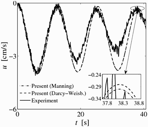
Figure 8 Measured and computed piezometric heads 14.1 m from upstream end for tests of Vasconcelos et al. (Citation2006)
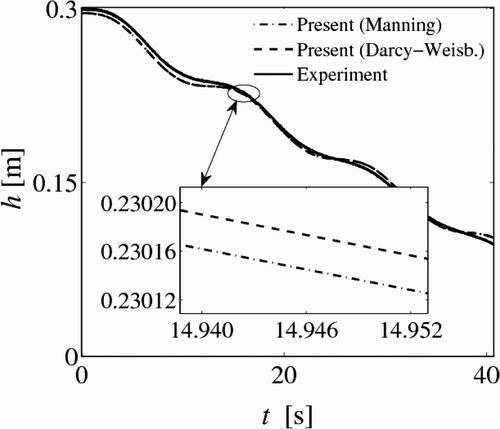
The reason for the velocity oscillations () may not be clear at first. However, by taking a look at the piezometric head plot (), the aforementioned oscillations start to make sense. The velocity at a given section is associated with the local difference in piezometric head at both sides of the section. In the test, the outflow from the upstream tank creates a variation of piezometric head in the whole pipeline. Since both tanks are relatively small and as the system tends to steady state, oscillations in the piezometric head are produced (). These in turn cause oscillations in the flow velocity.
5.3 Experiments of Zhou: no air release
The test setup of Zhou Citation(2000) consisted of an horizontal galvanized steel pipe of variable length with an inside diameter of 35 mm connected to a pressure tank at its upstream end. Inflow to the pressure tank provided with a pressure regulator facilitated a range of approximately constant driving heads at the pressure tank. The galvanized steel pipe consisted of three sections, separated by three quarter-turn valves. These provided three different initial air volume and water column length scenarios. The downstream pipe end was either sealed to form a dead-end, or outfitted with a cap containing a centred sharp-edged orifice. The initial conditions for the tests with and without air release consisted of two columns of fluid separated by a valve, in which the upstream column was always filled with water (pressurized) and the downstream column (receiving pipe) was either filled totally with air at atmospheric pressure (dry receiving pipe) or partially filled with water (wet receiving pipe). The air–water flow interaction in all tests was achieved by manually opening the quarter-turn valve separating the two columns of fluid. The tests were repeated up to five times because the recorded data sets varied significantly.
Zhou Citation(2000) defined three types of pressure oscillation patterns depending on the relative size of the leakage orifice. Type 1 (zero or relative small orifice size) pattern is characterized by the dominant effect of the air cushioning and a negligible effect of water hammer impact pressure. Type 2 (relative intermediate orifice size) pattern is characterized by similar effects of the air cushioning and water hammer impact pressure. Type 3 (relative large orifice size) pattern is defined by the dominant effect of water hammer impact pressure and a negligible effect of air cushioning.
Due to space limitations, only one test of Zhou Citation(2000) with no air release is considered herein. This test resembles Type 1 pattern. The pipe length used by Zhou Citation(2000) was 8.96 m, and 10 m for the test used in the next section (air release). The absolute pressure head in the pressure tank was for this test case H o */H b * = 2.43, the initial water column length was 89% of the total pipe length (λ o = 0.89) and y/d = 0.4 (wet receiving pipe). For the initial model conditions, the air volume above the free surface zone was an air pocket of zero gauge pressure head and atmospheric pressure air density. The simulated and measured absolute pressure head traces at the downstream pipe end are shown in . The simulated pressure head trace was obtained using 200 cells, a Courant number of C = 0.80, a Manning roughness coefficient of 0.012 m1/6 and the experimentally obtained pressure wave celerity of a = 700 m/s.
Figure 9 Experimental and simulated gauge pressure heads for H o */H b * = 2.43, λ o = 0.89, y/d = 0.4
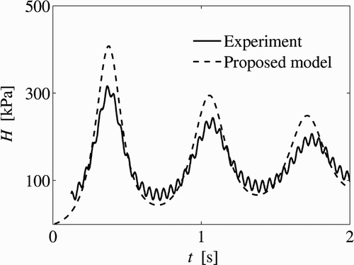
As is observed from , the simulated pressure head trace has a fair agreement with that of the test. In particular, the amplitude and frequencies of the pressure oscillations are reproduced fairly well. The differences between the numerical simulation and the test may be attributed to the simplicity of the 1D model for simulating complex hydrodynamic–thermodynamic processes such as the dynamics of formation and propagation of air pockets in pipelines. It is acknowledged that the simulation results for air release and no air release were not significantly sensitive to the value of the pressure wave celerity used.
5.4 Experiments of Zhou: with air release
Due to space limitations, only one test of Zhou Citation(2000) with air release is considered below of which the parameters were H o */H b * = 4.57, λ o = 0.8, y/d = 0 and d o /d = 0.028. The pipe length used for this test was 10 m. The simulated and measured absolute pressure head traces at the downstream pipe end are shown in . The simulated pressure head traces were generated using 200 cells, C = 0.80, n = 0.012 m1/6 and a = 1000 m/s, obtained experimentally.
Figure 10 Experimental and simulated gauge pressure heads for H o */H b * = 4.57, λ o = 0.8, d o /d = 0.028, y/d = 0
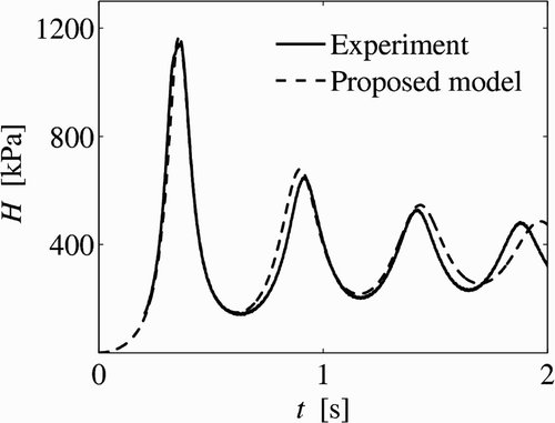
As is seen from , the simulated results fairly agree with the test measurements. As mentioned earlier, the proposed model gives a fair agreement with tests only for no air release or under small air release conditions. For intermediate or large release conditions (d o /d > ∼5%), the air–water flow is far from being 1D (Zhou et al. Citation2002) so that a 1D model cannot be used. If the proposed model is used for intermediate or large release conditions, large discrepancies with test data result are obtained (not shown).
6 Conclusions
An FV model was built upon earlier work with the aim of simulating free surface flows, pressurized flows and their simultaneous occurrence in single and two-phase flow conditions. This research presents part of this model for simulating mixed flows in single and two-phase flow conditions. In our model, the free surface region is simulated using the modified 1D Saint-Venant equations accounting for air pressurization, the pressurized region is simulated using the classical 1D compressible water hammer equations and open-channel-pressurized flow interfaces are simulated by enforcing mass, momentum and energy relations across open-channel-pressurized flow interfaces. The accuracy and robustness of the proposed model are investigated using four test cases. The key results are as follows:
-
The proposed model accurately describes complex flow features, such as positive and negative mixed flow interfaces, interface reversals and open-channel surges. In particular, the model simulates negative interfaces in mixed flow conditions having supercritical flow in the free surface region. This is achieved by using the HLL-Riemann solver in the free surface region that automatically handles sub-critical and supercritical flows. It appears that no mixed flow model was formulated for negative interfaces for supercritical flow in the free surface region. The model also simulates negative pressures in pressurized flow regime.
-
In two-phase flow conditions, the proposed model reproduces with fair accuracy the frequency and amplitude of the pressure oscillations only for small air release conditions. For intermediate or large release conditions, the air–water flow is far from being 1D so that a 1D model cannot be used. If the proposed model is used for intermediate or large release conditions, large discrepancies with the test data result.
-
Unlike previous approaches that rely on the speed of open-channel-pressurized flow interfaces at the boundaries of an air pocket for computing the volume change of the air pocket, the volumetric change is herein computed using the net flow discharge flux evaluated at the air pocket boundaries, which leads to a robust model.
-
Overall, the proposed model is robust and capable of simulating transient flows ranging from dry-bed flows, to free surface flows, to partly free surface-partly pressurized flows, to fully pressurized flows in single and two-phase flow conditions. Furthermore, it can simulate any transient-mixed flow condition for realistic pressure wave celerities.
Notation
| a | = |
pressure wave celerity |
| A | = |
hydraulic area |
| c | = |
gravity wave celerity |
| C | = |
Courant number |
| d | = |
conduit diameter |
| F | = |
Froude number |
| F | = |
flux vector |
| g | = |
acceleration due to gravity |
| h | = |
piezometric depth |
| H | = |
gauge air pressure head |
|
| = |
|
| k | = |
heat capacity ratio |
| m | = |
mass of air |
| n | = |
Manning roughness coefficient |
| p | = |
pressure acting on centre of gravity |
| p¯ | = |
average pressure of water column |
| Q | = |
discharge |
| R | = |
Reynolds number |
| S | = |
vector containing source terms |
| s | = |
wave speed |
| T | = |
top width |
| t | = |
time |
| u | = |
water velocity |
| U | = |
vector of flow variables |
| V | = |
volume of air pocket |
| w | = |
speed of mixed flow interface |
| x | = |
longitudinal coordinate |
| y | = |
piezometric depth above channel bottom |
| Y | = |
expansion factor |
Superscripts
| n | = |
computational time level |
| * | = |
absolute values (e.g. absolute pressure) |
Subscripts
| a | = |
refers to air |
| b | = |
atmospheric conditions |
| f | = |
pressurized flow state |
| i | = |
mesh point location in x direction |
| p 1 | = |
left side of mixed flow interface |
| p 2 | = |
right side of mixed flow interface |
| ref | = |
reference state |
| w | = |
water |
Acknowledgements
This work was conducted at the University of Illinois at Urbana-Champaign as part of the studies for the Tunnel and Reservoir Plan Modeling Project in Chicago, IL. The authors thank the Metropolitan Water Reclamation District of Greater Chicago for their financial support. The authors also gratefully acknowledge Dr Fayi Zhou, Profs. M. Ivetic and Jose Vasconcelos, and Engineer B. Trajkovic for providing their experimental data. Dr Zhou also provided insightful comments and suggestions on the model for air entrapment and air release. The second author wishes to acknowledge the Hong Kong Research Grant Council, Project No. 613407.
References
- Arai , K. and Yamamoto , K. Transient analysis of mixed free-surface-pressurized flows with modified slot model 1: Computational model and experiment . Proc. 4th ASME-JSME Joint Fluids Engrg. Conf. Honolulu, HW (CD-ROM)
- Bourdarias , C. and Gerbi , S. 2007 . A finite volume scheme for a model coupling free surface and pressurised flows in pipes . J. Comput. Appl. Math. , 209 ( 1 ) : 109 – 131 .
- Bryson , A. E. 1964 . “ Waves in fluids. Videorecording presented by National Committee for Fluid Mechanics Films ” . Chicago IL Encyclopedia Britannica Educational Corporation . Produced by Educational Services
- Capart , H. , Sillen , X. and Zech , Y. 1997 . Numerical and experimental water transients in sewer pipes . J. Hydraulic Res. , 35 ( 5 ) : 659 – 672 .
- Cardle , J. A. 1984 . “ An investigation of hydraulic transients in combination of free surface and pressurized flows ” . Twin Cities, MN : Department of Civil and Mineral Engineering, University of Minnesota . PhD thesis
- Cardle , J. A. and Song , C. C.S. 1988 . Mathematical modeling of unsteady flow in storm sewers . Int. J. Eng. Fluid Mech. , 1 ( 4 ) : 495 – 518 .
- Cardle , J. A. , Song , C. C.S. and Yuan , M. 1989 . Measurements of mixed transient flows . J. Hydraul. Eng. , 115 ( 2 ) : 169 – 182 .
- Guinot , V. 2003 . Godunov-type schemes , Amsterdam, NL : Elsevier .
- Hamam , M. A. and McCorquodale , J. A. 1982 . Transient conditions in the transition from gravity to surcharged sewer flow . Can. J. Civ. Eng. , 9 ( 2 ) : 189 – 196 .
- León , A. S. 2006 . “ Improved modeling of unsteady free surface, pressurized and mixed flows in storm-sewer systems ” . In PhD thesis , Urbana, IL : Department of Civil and Environmental Engineering, University of Illinois at Urbana-Champaign .
- León , A. S. and Ghidaoui , M. S. 2010 . Discussion of numerical oscillations in pipe-filling bore predictions by shock-capturing models . J. Hydraul. Eng. , in press
- León , A. S. , Ghidaoui , M. S. , Schmidt , A. R. and García , M. H. 2006 . Godunov-type solutions for transient flows in sewers . J. Hydraul. Eng. , 132 ( 8 ) : 800 – 813 .
- León , A. S. , Ghidaoui , M. S. , Schmidt , A. R. and García , M. H. 2007 . “ An efficient finite-volume scheme for modeling water hammer flows ” . In Contemporary modeling of urban water systems 15 , Edited by: James , W. 411 – 430 . Toronto, , Canada : CHI .
- León , A. S. , Ghidaoui , M. S. , Schmidt , A. R. and García , M. H. 2008 . An efficient second-order accurate shock capturing scheme for modeling one and two-phase waterhammer flows . J. Hydraul. Eng. , 134 ( 7 ) : 970 – 983 .
- León , A. S. , Ghidaoui , M. S. , Schmidt , A. R. and García , M. H. 2009 . Application of Godunov-type schemes to transient mixed flows . J. Hydraulic Res. , 47 ( 2 ) : 147 – 156 .
- León , A. S. , Liu , X. , Ghidaoui , M. S. and García , M. H. 2010 . A junction and drop-shaft boundary conditions for modeling free surface, pressurized, and mixed free surface-pressurized transient flows . J. Hydraul. Eng. , tentatively accepted
- LeVeque , R. J. 2002 . Finite volume methods for hyperbolic problems , Cambridge, , UK : Cambridge Press .
- Martin , C. S. Entrapped air in pipelines . Proc. 2nd Intl. Conf. Pressure Surges . pp. 15 – 28 . British Hydromechanics Research Association Cranfield UK .
- Nujic , M. 1995 . Efficient implementation of non-oscillatory schemes for the computation of free-surface flows . J. Hydraulic Res. , 33 ( 1 ) : 101 – 111 .
- Politano , M. , Odgaard , A. J. and Klecan , W. 2007 . Case study: Numerical evaluation of hydraulic transients in a combined sewer overflow tunnel system . J. Hydraul. Eng. , 133 ( 10 ) : 1103 – 1110 .
- Sanders , B. F. 2001 . High-resolution and non-oscillatory solution of the St Venant equations in non-rectangular and non-prismatic channels . J. Hydraulic Res. , 39 ( 3 ) : 321 – 330 .
- Song , C. C.S. , Cardle , J. A. and Leung , K. S. 1983 . Transient mixed-flow models for storm sewers . J. Hydraul. Eng. , 109 ( 11 ) : 1487 – 1503 .
- Toro , E. F. 2001 . Shock-capturing methods for free-surface shallow flows , Chichester, , UK : Wiley .
- Trajkovic , B. , Ivetic , M. , Calomino , F. and D'Ippolito , A. 1999 . Investigation of transition from free surface to pressurized flow in a circular pipe . Water Sci. Technol. , 39 ( 9 ) : 105 – 112 .
- Vasconcelos , J. G. 2005 . “ Dynamic approach to the description of flow regime transition in stormwater systems ” . In PhD thesis , Ann Arbor, MI : Department of Civil and Environmental Engineering, University of Michigan .
- Vasconcelos , J. G. , Wright , S. J. and Roe , P. L. 2006 . Improved simulation of flow regime transition in sewers: Two-component pressure approach . J. Hydraul. Eng. , 132 ( 6 ) : 553 – 562 .
- Wang , K-H. , Shen , Q. and Zhang , B. 2003 . Modeling propagation of pressure surges with the formation of an air pocket in pipelines . Comput. Fluids. , 32 ( 9 ) : 1179 – 1194 .
- Yen , B. C. 1991 . “ Hydraulic resistance in open channels ” . In Channel flow resistance: Centennial of Manning's formula , 1 – 135 . Littleton CO, , USA : Water Resources Publications .
- Yuan , M. 1984 . “ Pressurized surges ” . Twin Cities, MN : Department of Civil and Mineral Engineering, University of Minnesota . MSc thesis
- Zhou , F. 2000 . “ Effects of trapped air on flow transients in rapidly filling sewers ” . Edmonton, CA : Department of Civil and Environmental Engineering, University of Alberta . PhD thesis
- Zhou , F. , Hick , F. E. and Steffler , P. M. 2002 . Observations of air–water interaction in a rapidly filling horizontal pipe . J. Hydraul. Eng. , 128 ( 6 ) : 635 – 639 .
