Abstract
The effects of dimensionless parameters and boundary friction on air-entraining vortices and the critical submergence of an intake located in no-circulation imposed cross-flow and still water are investigated. It is found that limit values affect these vortices and the critical submergence, depending on the flow and geometrical conditions. The slower the cross-flow is, the higher these limit values are. The boundary friction effects on air-entraining vortices at intakes located in both a cross-flow and still water are also examined. The boundary section close to the free surface has a much larger effect than the boundary section away from it. The frictional effect of a boundary section on an air-entraining vortex depends on the distance between the boundary and the vortex centre at the free surface (above the intake centre). The boundary has maximum frictional effect if it is located at the vortex centre.
1 Introduction
The vertical distance between the intake centre and the water surface is referred to as submergence S. If S is below a certain minimum, the intake entrains air by means of free air-core vortices (1). The submergence at which the tip of the air-core vortex reaches the intake is called critical (subscript c) submergence S c (2). If S < S c , air enters the intake (3), causing hydraulic problems such as discharge reduction, vibrations, and loss of efficiency in turbines, pumps, and water-conveying structures. Extensive research has been conducted on air-entraining vortices (Anwar et al. Citation1978, Ansar et al. Citation2002, Werth and Frizzell Citation2009). Hydraulic engineers frequently discuss the effects of dimensionless parameters and the similarity conditions between model and prototype on air-entraining vortices.
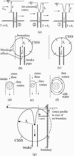
Figure 1 Definition scheme: (a) air-entrainment to intake, (b) boundary blockage, (c) no boundary blockage (except due to intake pipe), and free vortex in cross-flow (d) with and (e) without boundary effects, (f) free-vortex in still water with boundary effects, (g) vortex profile and a boundary
Studies on the limit values of the dimensionless parameters related to air-entraining vortices at intakes located in still water include Jain et al. Citation(1978), Anwar et al. Citation(1978), Padmanabhan and Hecker Citation(1984), Odgaard Citation(1986), or Hite and Mih Citation(1994). Only Gulliver and Rindels Citation(1987) investigated the variation of critical submergence with the Froude number of an intake located in a circulation-imposed cross-flow without yet mentioning the limit values. There is no doubt that these limit values differ for intakes in cross-flow and still water.
The limit values of the dimensionless parameters on air-entraining vortices, and S c of an intake located in a developed cross-flow, are experimentally investigated herein. It was found that these depend on the flow and geometrical conditions. Moreover, a boundary section close to the free surface has a much larger frictional effect than the boundary section away from it.
2 Dimensional analysis
The functional relationship involving S c of a pipe intake located in a rectangular channel can be written as
A solid boundary has two types of effects on S c :(1) flow “blockage” and (2) “friction”. If the intake clearance to the boundary is less than S c , the boundary cuts CSSS and causes a loss in surface area of CSSS. In reality, this is the loss of intake discharge caused by a boundary. This loss due to a boundary is called “blockage effect” of the boundary (. If the clearance of the solid boundary to the intake is larger than S c , the boundary does not intersect CSSS, resulting in no “blockage” effect (. S c varies with boundary blockage and boundary friction, therefore. S c increases and decreases with boundary blockage and boundary friction respectively.
Boundaries or sections were thought to have the same frictional effects on air-entraining vortices. In reality, this is not the case. Since the air-core vortex starts at the free surface, the friction of boundary section intersecting the vortex profile at the free surface is effective, thereby reducing the air-core vortex (). Surface tension and viscous effects are insignificant for intake flow provided W >120 (Jain et al. Citation1978), R >1.1×10⁵ (Anwar et al. Citation1978), R >1.4×10⁵ and W >720 (Odgaard Citation1986), and R >7.7×10⁴, W >600 (Padmanabhan and Hecker Citation1984). These limit values differ because each researcher used different geometrical and flow conditions. The boundary blockages on the intake flows were also varied in their experiments. Jain et al. Citation(1978), and Kocabaş and Yıldırım Citation(2002) demonstrated that S c is sensitive to K for which currently no limit value is available.
To suppress boundary blockage on the intake flow and thus to examine exclusively the effects of F, R, and W, the clearances of the channel flow boundaries to the intake were taken larger than S
c
(Yıldırım et al.
Citation2000). Therefore, their effects are ignored. Herein, no circulation on the approach flow was imposed (K = 0) and no end-wall was provided. Hence, EquationEq. (2) simplifies to
3 Experiments on scale effects
3.1 Test procedure
The test set-up involved a horizontal rectangular channel 50 cm wide, and the test procedure was as described by Yıldırım et al. Citation(2000). The channel used herein had no dead end. A steel intake pipe of D = 5.32 cm and wall thickness of about 3 mm was used. The vertical intake pipe with a crest level of 21.28 cm (c/D = 4) above the channel bottom was located on the channel axis. To present S c without any boundary effect, the intake clearances to the channel boundaries were kept larger than S c (b 1/D = b 2/D = 4.70 > S c /D, c/D = 4 > S c /D).
To examine the circulation effect on the limit values for V/U ∞ = 37, tests were also conducted using four evenly spaced 2 mm thick steel rectangular plate vanes extending across the canal flow depth, penetrating the free surface, and with 15° relative to the channel axis. The vanes were located 180 cm upstream of the intake (Taştan Citation2010).
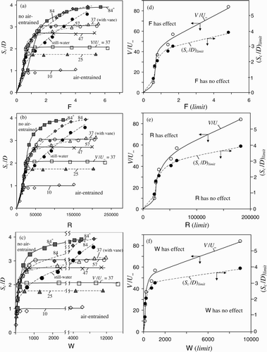
To observe the intake size effect, a set of tests was performed with D = 3.66 cm for V/U ∞ = 84 (c/D = 4 > S c /D) and denoted V/U ∞ = 84* in the figures presented below. The water surface elevation and the intake discharge were measured by means of a point gage to ±0.5 mm and a thin-plate V-notch weir to ±2%. Reading errors of about ±1 mm caused a total uncertainty of ±1.5 mm, corresponding to ±0.03(S c /D). In addition to the intake flow patterns, both the free surface and the subsurface vortices contributed to pipe flow swirl, setting up unsteady flow conditions (Padmanabhan and Hecker Citation1984). These instabilities caused total data uncertainties in S c , and of the intake discharge Q of less than ±1.5 mm and 0.2 l/s, respectively. These correspond to uncertainties in F, R, and W of about ±0.10, ±4.7×10³, and ±6, respectively. The data of F, R, and W therefore scatter in . For comparison purposes, one set of data conducted on an intake located in still water (see below, neither circulation imposed nor boundary blockage, D = 5.32 cm) was also included in .
3.2 Experimental results
All test data are shown in . Note that the section of the line related to data of V/U ∞ = 84 for F<2 is approximated in , because it was difficult to obtain data in this range for D = 5.32 cm, requiring a wider channel than used herein to impose U ∞ i.e. <2.5 cm/s. To compute W, σ = 0.072 N/m was taken (Jain et al. Citation1978).
The ranges of F, R, and W for prototype intakes are also stated below. Their ranges in laboratory studies were F = 0.26 to 0.38, R = 9.5×10⁴ to 1.8×10⁵, and W = 454 to 1933 (model scales 1 : 4.5 to 1 : 9.25; Werth and Frizzell Citation2009), F = 1 to 5 (Odgaard Citation1986), F = 0.25 to 2.5 (Gulliver and Rindels Citation1987), and R = 7×10⁴ to 1.4×10⁵ and W = 6×10² to 2×10³ (model scale 1 : 4; Padmanabhan and Hecker Citation1984), and R = 1.9×10⁵ to 3.4×10⁵ and W = 2×10³ to 8×10³ (model scale 1 : 2; Padmanabhan and Hecker Citation1984). The present data relate to F = 0.22 to 8.80, R = 8.3×10³ to 2.3×10⁵, and W = 1.9×101 to 1.48×10⁴.
4 Discussion of results
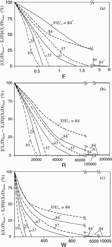
shows that beyond certain values of F, R, and W, S c is independent of these, such that the limit values of S c may be defined. For example, for V/U ∞ = 37 (no vane), the limit values of F, R, and W are 0.79, 29690, and 239, respectively (. Below these values S c /D varies with F, R, and W. The limit values decrease as the approach flow velocity is increased, because the inertia forces generated by the cross-flow dominate the viscous, gravity, and surface tension forces and their effects become negligible on air-entraining vortices. If the cross-flow is reduced, the reverse is true. Let (S c /D) limit = limit value of S c /D (subscript limit) of F, R, and W. (S c /D) limit can be considered equal to the maximum of S c /D for a given flow and geometry. The variations in V/U ∞ and (S c /D) limit with the limit values of F, R, and W without boundary blockage (Yıldırım et al. Citation2000) are shown in .
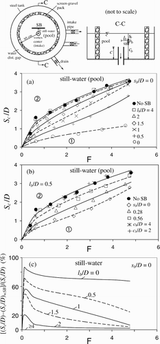
For an intake in still water, it is difficult to obtain data for (S c /D) limit and limit values of F, R, and W, resulting in the following approximation. Since the approach flow velocity is very small for V/U ∞ = 84 or 84*, the limit values of F, R, and W may be considered identical with those for V/U ∞ = 84 or 84*, which are larger than those given in the literature. In reality, still water does not necessarily mean zero velocity flow because velocity develops toward the intake. Therefore, the error of this approximation is negligible. Yıldırım and Kocabaş Citation(1998), and Yıldırım et al. Citation(2000) demonstrated that U ∞ = 2V s with V s the velocity at CSSS for still water. The variations of [(S c /D) limit −(S c /D)]/(S c /D) limit with F, R, and W are shown in , resulting from . The limit values of F, R, and W are seen to considerably increase with circulation () because this causes increased vortex strength, centrifugal and inertia forces, and surface disturbances stimulating the vortex occurrence.
The present ranges of F, R, and W cover these common in laboratory use and the data of other researches. According to Gulliver and Rindels Citation(1987), typical prototype hydropower turbine intakes have D = 3 m, V = 2.5 m/s, thus F = 0.50, R = 7.4×10⁶, and W = 2.64×10⁵. A typical prototype pump intake is (Iversen Citation1953) D = 0.50 m, Q = 0.16 m3/s, thus V = 1 m/s, F = 0.46, R = 4.5×10⁴, and W = 6.26×10³. Finally, intakes of prototype cooling systems are characterized by (Sweeney et al. Citation1982) D = 3 m, Q = 12.5 m3/s, thus V = 1.8 m/s, F = 0.34, R = 5.3×10⁶, and W = 1.37×10⁵. In a hydraulic laboratory, it is difficult to generate identical R and W values as in prototype facilities. Hecker Citation(1981) provided a list of prototype ranges for pumps, hydropower turbine, and cooling system intakes of model scales from 1 : 12 to 1 : 122. Considering prototype intakes of D = 0.50–3 m, D = 5.32 cm used herein corresponds to model scales of 1 : 12 to 1 : 60, i.e. within the ranges of model scales in practice. Therefore, the present results can be used for prototype intakes.
Note that the lines in the figures relating to still water, and V/U ∞<37 (cross-flow), are based on the “least square method”. The lines for V/U ∞ ≥ 37 approximate the test data because the least square method did then not give physically meaningful fits, especially in regions where the data indicate that S c /D is independent of F, R, and W.
5 Effect of boundary friction
5.1 Test procedure
Since both inevitable blockage and frictional effects of a complete boundary coexist, it is impossible to investigate the frictional effect only on air-entraining vortices. The boundary should have a negligible blockage effect on S c that was achieved as follows. Consider , with the upper boundary section AB above the profile of the air-entraining vortex causing a negligible blockage but large friction effects on S c . Conversely, the boundary section CE (g) below the profile of the air-entraining vortex causes a large blockage but negligible friction on S c . Therefore, only the very upper section of the boundary penetrating or close to the free surface allows one to examine the frictional effect. According to the dimensionless profile of an air-entraining vortex (Hite and Mih Citation1994), the depth of the air-entraining vortex rapidly decreases and becomes asymptotic to the horizontal water surface as the radial distance from the vortex centre increases. This indicates that a boundary penetrating the free surface for a small height (like a ruler laying on its large-dimension edge) can be used to examine the effect of the boundary friction on S c .
5.2 Experimental results
To examine boundary friction on an air-core vortex under critical intake conditions, a ruler type Strip-Beam (SB) was used. To determine its length and the height, two indications are considered:
-
Boundary section remaining within CSSS has important effect on air-entraining vortex (Yıldırım et al. Citation2000). The length of SB should be larger than or equal to the diameter of CSSS (2S c ). In , test results without SB infer a maximum of S c /D ≅ 3–4. Therefore, the length of SB to be used should be equal to or larger than 8D. For safety reasons, a length of 10D was considered. To check this approach, two additional tests were conducted with 20D (100 cm). The difference between the test results with these two lengths was only 3%.
-
The height of SB should be equal to or larger than the depression depth (profile of air-core vortex as developed without SB) at the clearance of SB to the vertical intake axis. Under critical intake condition in still water, its dimensionless profile is given by Hite and Mih Citation(1994), indicating that the maximum depth of the surface depression in the irrotational-vortex region is about 0.1S c . Since the maximum of S c /D ≅ 3–4 herein, the height of SB is taken equal to 0.3D (1.5 cm). A 2 mm thick steel sheet SB was used (). Let h b be the height of SB, l b the clearance of SB to vertical axis of the vertical intake, s b the penetration of upper edge of SB, and c b the clearance of lower SB edge to canal bottom. For h b /D = 0.3 and pre-determined values of l b , s b , and c b , the SB was positioned horizontally on its larger-dimension edge and adjusted parallel to the approach flow ().
Figure 4 Effects of boundary-friction on S
c
/D for c/D = 4, h
b
/D = 0.3 (a) and (b) SB at free surface (s
b
/D = 0), (c) for different SB locations across depth (l
b
/D = 0.5), ![]()
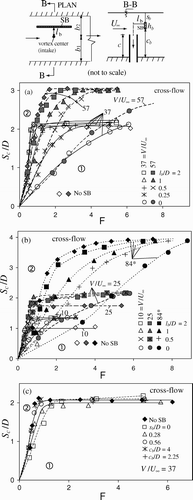
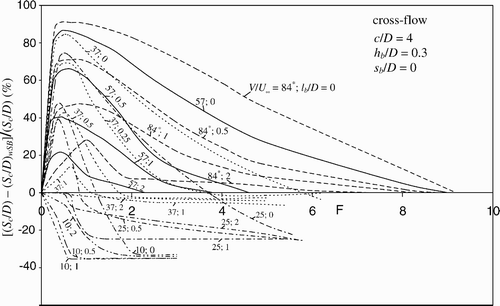
Experiments were conducted by locating the SB for various l b , s b , and c b across the flow depth without boundary blockage (b 1/D = b 2/D = 4.70 > S c /D, c/D = 4 > S c /D). Test results are presented in . To examine the frictional effects of the boundary section away from the free surface, tests for only V/U ∞ = 37 were conducted with the SB located at position l b = 0.5 and various c b and s b across the depth (. Along with and , [(S c /D)–(S c /D) wSB ]/(S c /D) is plotted in (lines are average of small fluctuations) in which wSB stands for “with SB”.
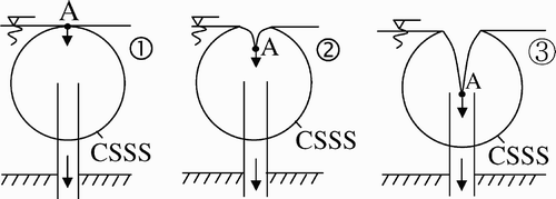
The data indicate that both friction and turbulence affect air-entraining vortex. Since it reduces the circulation at the free surface, the frictional effect reduces the occurrence of the air-core vortex. The frictional effect of the SB reaches its maximum if it is located at the centre of the air-core vortex at or close to the free surface () because the CSSS is tangential to the free surface at its summit point A corresponding to the vortex centre at the free surface (). The velocity at the CSSS is radial.
The free-surface particle A is the key to develop the air-core vortex. In the presence of the SB at A (l b = 0, s b = 0), the movement of particle A is highly restricted due to the no-slip condition. Hence, the generation of a surface depression or the occurrence of the air-entraining vortex is considerably reduced. In the region where [(S c /D)–(S c /D) wSB ]/(S c /D) > 0 (), the data show that S c drops if the approach flow becomes turbulent, indicating that turbulence reduces the occurrence of the air-core vortex. During the tests conducted with SB, it was observed that several small vortices of opposite directions develop at the free surface, inferring that the SB increases the local turbulence above an intake. Hence, SB causes a decrement in S c /D (positive effect of SB). The well-known Stokes’ law dictates that the sum of these vortices of opposite directions reduces the circulation around a closed contour at the free surface. Turbulence may also spoil the point sink characters of an intake, occurrence and collapse of the CSSS (Kocabaş and Yıldırım Citation2002), and movement of particle A toward the intake (). These are the reasons for a reduced vortex occurrence due to turbulence. Conversely, at large F, [(S c /D)–(S c /D) wSB ]/(S c /D) < 0 (), indicating that the turbulence level drops due to a local blocking effect. In this region, SB causes an increment in S c /D (negative effect of SB on S c /D). Tests with and without SB were also conducted for a pipe intake located in a pool (still water, net working pool diameter = 190 cm, D = 5.32 cm, no boundary blockages c/D = 4 > S c /D, no circulation imposed) (). Note that for c/D ≥ S c /D (i.e. c/D = 4 and S c /D attains 4) minor effects of intake pipe blockage cannot be completely excluded.
Figure 7 Effect of boundary-friction on S
c
/D in still water (c/D = 4, h
b
/D = 0.3): (a) SB at free surface, (b) SB at various positions across depth, (c) effect of boundary friction on S
c
/D, ![]()
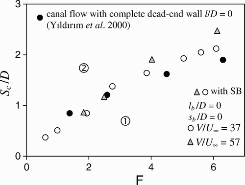
To obtain an idea of the boundary frictional effect away from the free surface, consider two typical test results from Iversen Citation(1953) obtained in a dead-end rectangular channel sump for Q = 13.90 l/s, D = 16.2 cm. They are for Run No 30: b 1/D = b 2/D = 1.5, c/D = 1, l/D = 1.5, S c /D = 1.07, and for Run No 63: b 1/D = b 2/D = 1.5, c/D = 2, l/D = 1.5, S c /D = 1.11. Although the bottom clearance in Run 30 is slightly smaller than S c , i.e. negligible floor blockage, as the bottom clearance was increased by 100%, the change in S c was only 4%, due to the floor blockage rather than floor friction. This result infers that friction effects of the boundary sections away from the free surface are negligible. The test results of Yıldırım et al. Citation(2000) (, or Table 1) with a complete dead-end wall of zero clearance (l/D = 0, V/U ∞ = 34–47, D = 5.32 cm, horizontal pipe passing through the dead-end wall) and the present study with SB of l b /D = 0, s b /D = 0, V/U ∞ = 37, and 57, D = 5.32 cm are compared in . The frictional effect of SB on S c is seen to be almost the same as that of a complete boundary penetrating the free surface. This result confirms that only the section of the boundary penetrating or close to the free surface has a friction effect on S c .
5.3 Explanatory note
As seen from and , the frictional effect of SB becomes negligible for l b ≥ l blimit . Let BCFS be the boundary penetrating or close to free surface in general, c l the clearance of BCFS to vortex centre, and c llimit the value of c l for which friction effect of BCFS is negligible. In reality, c l = l b , and c llimit = l blimit of SB. The following comments are appropriate:
-
For c l ≥ S c , BCFS has no blockage or friction effects on S c .
-
For c llimit ≤ c l ≤ S c , BCFS has only a blockage effect but its frictional effect on S c is negligible.
-
As c l gets smaller ( and ), the frictional effect of BCFS further increases and becomes compatible with its blockage effect.
Depending on V/U ∞, F, R, and W, the frictional effect of BCFS may dominate its blockage effect and become the prevailing factor on S c . For a no-circulation-imposed cross-flow, and still water, one can estimate l blimit (c llimit ) from and .
6 Conclusions
From this study, the following conclusions may be drawn:
-
The limiting values of the Froude, Reynolds, and Weber numbers affecting air-entraining vortices depend on the flow and geometrical conditions. These values are no constants.
-
The friction effects of boundary sections penetrating or close to the free surface of air-entraining vortices depend on the ratio of intake to approach flow velocities, plus the Froude, Reynolds, and Weber numbers.
-
If the vertical clearance of the uppermost edge of a submerged boundary to the free surface is larger than 0.1 times the critical submergence (that is for the same discharge but in case of no boundary), its frictional effect on the critical submergence or on the air-entraining vortex is negligible.
Notation
| b | = |
clearance of intake centre |
| c | = |
clearance of channel bottom |
| c l | = |
clearance of BCFS to intake centre |
| D | = |
internal intake diameter |
| F | = |
intake Froude number |
| g | = |
gravity acceleration |
| h b | = |
height of SB |
| K | = |
intake circulation number |
| l | = |
clearance of intake to end-boundary |
| Q | = |
intake discharge |
| R | = |
intake Reynolds number |
| S | = |
submergence of intake |
| U ∞ | = |
approach flow velocity |
| V | = |
average intake velocity |
| W | = |
intake Weber number |
| Γ | = |
circulation |
| ν | = |
kinematic viscosity |
| ρ | = |
fluid density |
| σ | = |
fluid surface tension |
Subscripts
| 1 | = |
right-side channel wall |
| 2 | = |
left-side channel wall |
| b | = |
for SB |
| c | = |
critical |
| limit | = |
limit values of parameters |
| s | = |
velocity at CSSS |
Acknowledgements
This study has been financed by the Research Fund of Gazi University, Ankara, Turkey (Project No. 06/2009-03).
References
- Ansar , M. , Nakato , T. and Constantinescu , G. 2002 . Numerical simulations of inviscid three-dimensional flows at single and dual-pipe intakes . J. Hydraulic Res. , 40 ( 4 ) : 461 – 470 .
- Anwar , H. O. , Weller , J. A. and Amphlett , M. B. 1978 . Similarity of free vortex at horizontal intake . J. Hydraulic Res. , 16 ( 2 ) : 95 – 106 .
- Gulliver , S. J. and Rindels , A. J. 1987 . Weak vortices at vertical intakes . J. Hydraul. Eng. , 113 ( 9 ) : 1101 – 1116 .
- Hecker , G. 1981 . Model prototype comparison of free surface vortices . J. Hydraul. Div. ASCE , 107 ( 10 ) : 1243 – 1259 .
- Hite , J. E. and Mih , W. C. 1994 . Velocity of air-core vortices at hydraulic intakes . J. Hydraul. Eng. , 120 ( 3 ) : 284 – 297 .
- Iversen , H. W. 1953 . Studies of submergence requirements of high-specific speed pumps . Trans. ASME , 75 ( 4 ) : 635 – 641 .
- Jain , A. K. , Ranga Raju , K. G. and Garde , R. J. 1978 . Vortex formation at vertical pipe intakes . J. Hydraul. Div. ASCE , 104 ( 10 ) : 1429 – 1448 .
- Kocabaş , F. and Yıldırım , N. 2002 . Effect of circulation on critical submergence of an intake pipe . J. Hydraulic Res. , 40 ( 6 ) : 741 – 752 .
- Odgaard , A. J. 1986 . Free surface air core vortex . J. Hydraul. Eng. , 112 ( 7 ) : 610 – 620 .
- Padmanabhan , M. and Hecker , G. E. 1984 . Scale effects in pump sump models . J. Hydraul. Eng. , 110 ( 11 ) : 1540 – 1556 .
- Sweeney , C. E. , Elder , R. A. and Hay , D. 1982 . Pump sump design experience . J. Hydraul. Div. ASCE , 108 ( 3 ) : 361 – 377 .
- Taştan , K. 2010 . “ Characteristics of air-entraining vortex at an intake ” . PhD thesis (in progress). Department of Civil Engineering, Gazi University, Ankara, Turkey, [in Turkish].
- Werth , D. and Frizzell , C. 2009 . Minimum pump submergence to prevent surface vortex formation . J. Hydraulic Res. , 47 ( 1 ) : 142 – 144 .
- Yıldırım , N. and Kocabaş , F. 1998 . Critical submergence for intakes in still-water reservoir . J. Hydraul. Eng. , 124 ( 1 ) : 103 – 104 .
- Yıldırım , N. , Kocabaş , F. and Gülcan , S. C. 2000 . Flow-boundary effects on critical submergence of intake pipe . J. Hydraul. Eng. , 126 ( 4 ) : 288 – 297 .
