Abstract
An experimental investigation of the cavitation characteristics of high-velocity flow over an offset-into-flow with various heights and chamfers both in the presence and absence of aeration was conducted in a cavitation tunnel of the Hydraulics Laboratory, Zhejiang University of Technology in China. The 2- and 5-mm abrupt and sloping offsets into flows were employed to be models of surface irregularities. Cavitation phenomena of high-velocity flow over the various offsets were carefully observed. A range of air concentrations was considered. Variations of wall pressures downstream and upstream of the offset were measured in terms of the air concentration. The effects of air concentration and chamfer on the cavitation characteristics of the offsets were analysed. In addition, the cavitation cloud over the offset-into-flow and the turbulent boundary layer over a flat plate are compared.
1 Introduction
Chute or tunnel spillways for high dams involve high-velocity flow, so cavitation damage may occur if projections or depressions such as cylindrical and triangular protrusions, offsets into and away from the flow, and other irregularities during construction of flood release structures exist on the chute surface. A serious problem is cavitation damage. Hydraulic practice demonstrated that severe cavitation damage occurred even for irregularities of a few millimetres. An early case of cavitation damage was reported for Hoover Dam (Warnock Citation1947) within and just below its 50° vertical bend upon its initial and only operation in 1941. The velocity was as high as 45 m/s. The cavitation damage consisted of erosion of the concrete tunnel lining and underlying rock to a depth of 13.7 m and a length of 35 m, which was triggered by a bulge in the invert concrete. Another severe cavitation damage occurred in a right tunnel spillway of the Liujiaxia Hydropower Station in China (Liu Citation1983), arising from three 8 mm steel bars protruding on the concrete surface near the end of vertical bend of the tunnel spillway in 1972. The cavitation hole was 100 m long and 4.8 m deep.
Falvey's Citation(1990) measurements indicate that velocities of 12–20 m/s may cause cavitation damage at local irregularities along spillway or chute surfaces. Shalnev Citation(1951) investigated issues of cavitation damage due to surface irregularities on blades of hydraulic turbine. His experimental data indicated that cavitation was related to the relative height of an irregularity, to the velocity distribution within the boundary layer and to its thickness. Ball (Citation1959, Citation1963 and Citation1976) experimentally investigated the hydraulic consequences of surface irregularities and developed a relationship among the critical pressure, the critical velocity and its effect on cavitation inception for several typical irregularities. He suggested that a cavitation damage due to irregularities may be prevented, if the cavitation number of the overflow was higher than the incipient cavitation number of the irregularity. Holl Citation(1960) made experiments on cavitation inception of arc and triangular irregularities, to analyse the boundary layer effect on cavitation inception. Chen Citation(1962) suggested a numerical approach to control spillway surface irregularities based on his experimental data. Benson Citation(1966) investigated cavitation inception of a three-dimensional (3D) isolated irregularity. Arndt and Ippen Citation(1968) explored the characteristics of cavitation inception of an isolated irregularity on both smooth and rough surfaces. Wang and Zhou Citation(1979) suggested a numerical method to control overflow surface irregularities based on the cavitation intensity using prototype observations and model test data. Xu and Zhou Citation(1982) analysed the pressure distribution and the incipient cavitation number of arc and semi-arc irregularities in open-channel and pipe flows based on the theory of complex function. Liu Citation(1983) systematically investigated the incipient cavitation number of several types of irregularities for open-channel and pipe flows, and identified the Reynolds number and the velocity profile within the boundary layer as the main effects on incipient cavitation number. He proposed that the larger the aspect ratio of irregularity was, the lower is the incipient cavitation number.
As the cavitation phenomenon is inevitable, an economic and effective measure is the aerator to force aeration within the under-pressure cavitation zone or other locations liable to cavitation damage to prevent damage. Peterka Citation(1953) investigated the mechanism of cavitation control by aeration. The ratios of air to water discharges in his tests ranged from 0.4% to 7.4%. He observed bursting and hammer-beating sounds due to cavitation, which reduced with increasing air discharge; the cavitation noise vanished completely as 7% air was supplied. Rasmussen's Citation(1956) experimental tests indicated that an air–water ratio of 1% was sufficient to control cavitation for aluminum-alloy specimens. Colgate Citation(1959) determined a correlation between cavitation inception of multiple irregularities and wall turbulence. Colgate and Legas Citation(1972) applied aerators to control cavitation for rehabilitating cavitation damage due to irregularities in a tunnel spillway at the Yellowtail dam in the USA, resulting in no cavitation damage after remediation by epoxy sand grout. Field observations to control cavitation damage of a triangular irregularity by air supply to the left and right tunnel spillways and the left ski-jump spillway of flood release structures with different overflow type, head and air concentration were conducted by Deng and Ha Citation(1988) at Wujiangdu Hydropower Station, China. The cavitation damage of a 20 mm triangular irregularity was removed as the air concentration reached 1.1% and 50 mm for 4.1%. Similar studies were carried out by Johnson Citation(1963), Hu Citation(1983), Chai and Wu Citation(1995), Wilhelms and Gulliver Citation(2005), Bilus et al. Citation(2007), Hocevar et al. Citation(2007) or Dong et al. (Citation2008a, Citation2008b). Regarding the cavitation characteristics of the offset-into-flow, Cai Citation(1985) and Yuan and Zheng Citation(1990) investigated the effect of pressure fluctuation on cavitation inception. This research aims at experimentally testing the cavitation characteristics of the offset-into-flow in presence and absence of aeration.
2 Experimental facility and methodology
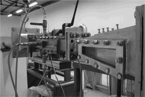
The test work was carried out at the Hydraulic Research Institute, Zhejiang University of Technology, China. The working sections of the tunnel system consisted mainly of a rectangular contraction, test and expansion sections made of stainless steel plates and processed by computer-controlled machine (). The dimensions of working sections involved a cross-sectional area of 2 × 3.5 cm2 50 cm long test section, the 20 cm long inflow and outflow cross-sections of the contraction section of 15 × 15 cm2 and 3.5 × 4 cm2, and the 40 cm long inflow and outflow of the expansion section of 3.5 × 4 cm2 and 15 × 15 cm2, and observation windows. Also, there was a transition between the contraction (expansion) and the test sections. The surface irregularity was abrupt involving sloping offsets-into-flow made of stainless steel processed by computer-controlled machinery. The offset-into-flow may be divided into four types: 2 mm abrupt, 2 mm sloping, 5 mm abrupt and 5 mm sloping. Locations of pressure transducers in the test section were −15, 15, 45, 75 and 105 mm from the leading offset edge (). The slope of the sloping offsets-into-flow was tan θ = 1/2.
The water discharge was measured with an UFLO2000P Ultrasonic Doppler flow meter, and the air discharge with LZB-15 and LZB-40 rotator flowmeters. MPX400D pressure transducers and the real-time data acquisition system SINOCERA-YE6263 were used to record wall pressures. The flow velocity ranged from 36.9 to 40.3 m/s.
3 Cavitation phenomena of offset-into-flow
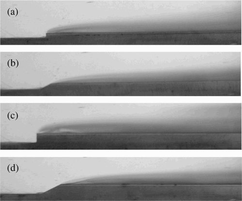
Cavitation phenomena of abrupt and sloping offsets-into-flow are shown in . and shows cavitation clouds due to the 2 mm abrupt and sloping offsets, and (c) and (d) due to the 5 mm abrupt and sloping elements. Accordingly, considerable cavitation phenomena of high-velocity flow over offset-into-flow are seen to occur no matter whether the offsets are abrupt or sloping. The thickness of the cavitation cloud over the sloping offset was thinner than that of the abrupt of same height, especially close to the leading offset edge. As the height of the offset increases, the thickness of cavitation cloud thickened ( and ).
Figure 3 Cavitation clouds over offsets-into-flow (a) 2 mm abrupt, (b) 2 mm sloping, (c) 5 mm abrupt and (d) 5 mm sloping
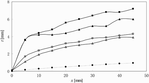
Considering a cavitation cloud over an offset-into-flow as a turbulent boundary layer growth over a flat plate, the boundary layer momentum deficit thickness δ2 can be expressed as
The velocity distribution within a turbulent boundary layer using the 1/7 power law is
Substituting
EquationEq. (3) into
EquationEq. (2)
gives
Based on Blasius's Citation(1913) formula, the wall shear stress is expressed as
Substituting
EquationEqs (4) and
Equation(5)
into
EquationEq. (6)
gives after integration
4 Measured pressure with and without aeration
The air concentration C is defined as
Table 1 Measured pressures with and without aeration
5 Cavitation number of offset-into-flow
5.1 Cavitation number without aeration
The cavitation number is essentially a pressure coefficient, reflecting the effect of pressure change on the fluid property, expressed as
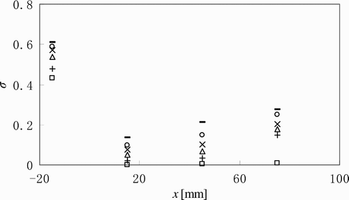
The cavitation numbers downstream and upstream of the offset without aeration are shown in . It follows that σ downstream of offset-into-flow is low almost approaching σ = 0, whereas σ ≅ 0.4 upstream of the offset.
Table 2 Cavitation numbers without aeration
5.2 Cavitation number of 2 mm abrupt offset-into-flow with aeration
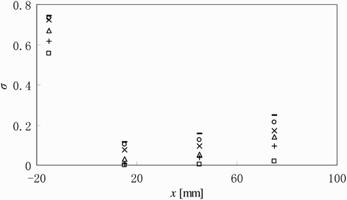
The cavitation number of the 2 mm abrupt offset is shown in . It follows that σ downstream of the offset without aeration nearly tends to zero. However, the cavitation number downstream of the offset with aeration gradually increases with the air concentration C = 2.3, 4.0, 6.0, 8.0 and 10.0%. Note that the cavitation number downstream of the test section decreases, because the measuring point was influenced by the expansion section. In presence of aeration, the cavitation number is therefore seen to first abruptly decrease and then gradually increase.
5.3 Comparison of cavitation numbers between 2 mm sloping and abrupt offsets
A comparison of the cavitation numbers between sloping and abrupt offsets 2 mm high is shown in . The difference of cavitation numbers between the 2 mm sloping and abrupt offsets is seen to be negligible for C = 2.3, 4.0, 6.0, 8.0, 10.0% and for C = 0.0%, due to the lower offset height.
5.4 Cavitation number of 5 mm abrupt offset with aeration
The variation of the cavitation number for the 5 mm abrupt offset is shown in , which is seen to be similar to that of the 2 mm abrupt offset (). Accordingly, the effect of offset height on σ is small.
5.5 Comparison of cavitation numbers between 5 mm sloping and abrupt offsets
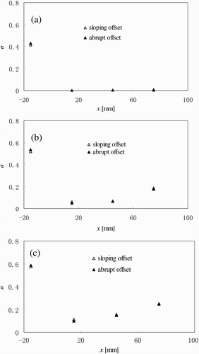
For 5 mm abrupt offsets, the variation in the cavitation number between the sloping and the abrupt as shown in differs from the 2 mm offset. The cavitation number of sloping offsets is obviously larger than that of abrupt offsets for C > 0.
6 Conclusions
Based on an experimental study of the cavitation characteristics of the abrupt and sloping offsets-into-flow of various heights, the following conclusions are made:
-
A thick cavitation cloud over the offset was generated even for an offset height of only 2 mm provided high-velocity flow in the order of 40 m/s is considered.
-
Using a sloping instead of an abrupt offset did not improve the cavitation number.
-
Negative pressures downstream of abrupt and sloping offsets approached −1.0 atmospheric pressure in the absence of aeration.
-
Aeration increases the pressure downstream of the offset considerably.
-
The cavitation numbers downstream of both the abrupt and sloping offsets nearly tend to zero in the absence of aeration. However, the cavitation number downstream of the offset gradually increases with the presence of aeration.
-
For 5 mm offsets, the cavitation number of the sloping offset was apparently larger than that of the abrupt in presence of aeration. In addition, the thickness of cavitation cloud over the offset is considerably larger than that of the corresponding boundary layer over a flat plate.
Notation
| C | = |
air concentration |
| h, h v | = |
absolute and saturated vapour pressure head |
| p | = |
wall pressure |
| Q a , Q w | = |
air and water discharge |
| R x | = |
Reynolds number of boundary layer |
| u | = |
velocity within boundary layer |
| U 0 | = |
approach flow velocity |
| x | = |
streamwise coordinate |
| δ | = |
thickness of boundary layer |
| δ2 | = |
momentum deficit thickness of boundary layer |
| σ | = |
cavitation number |
| τ0 | = |
wall shear stress |
Acknowledgements
The authors would like to acknowledge the support of the National Natural Science Foundation of China (Grant Nos: 50579067 and 50539070).
References
- Arndt , R. E.A. and Ippen , A. T. 1968 . Rough surface effects on cavitation inception . J. Basic Engng. ASME , 9 ( 3 ) : 249 – 261 .
- Ball , J. W. 1959 . Hydraulic characteristics of gate slots . J. Hydraulics Div. ASCE , 85 ( HY10 ) : 81 – 114 .
- Ball , J. W. 1963 . Construction finishes and high velocity flow . J. Construct. Div. ASCE , 89 ( CO2 ) : 91 – 110 .
- Ball , J. W. 1976 . Cavitation from surface irregularities in high velocity . J. Hydraulics Div. ASCE , 102 ( HY9 ) : 1283 – 1297 .
- Benson , B. W. 1966 . “ Cavitation inception on three dimensional roughness elements ” . In David Taylor Model Basin Report , Washington, DC : Hydromechanics Lab . 2104
- Bilus , I. , Predin , A. and Skerget , L. 2007 . The extended homogenous cavitation transport model . J. Hydraulic Res. , 45 ( 1 ) : 81 – 87 .
- Blasius , H. 1913 . “ Das Ähnlichkeitsgesetz bei Reibungsvorgängen in Flüssigkeiten ” . In VDI. Forschungsarbeit , Vol. 131 , 1 – 39 . Berlin, [in German] : Verein Deutscher Ingenieure .
- Cai , M. 1985 . “ Interaction between cavitation inception and pressure fluctuation of irregularities ” . In Collected Research Papers , Vol. 26 , 48 – 60 . Beijing, [in Chinese] : Water Conservancy and Hydroelectric Power Research Institute, Hydropower Press .
- Chai , G. and Wu , J. 1995 . “ Study of flood discharge and energy dissipation with high-head and large flow rate ” . In Research Report 85-208 , 116 – 142 . Kunming, [in Chinese] : Kunming Surveying Design Research Institute .
- Chen , C. 1962 . Control of cavitation number and surface irregularity on overflow dam . J. Hydraulic Engng. CHES , 7 ( 8 ) : 12 – 17 . [in Chinese]
- Colgate , D. 1959 . Cavitation damage of roughened concrete surfaces . J. Hydraulics Div. ASCE , 86 ( HY11 ) : 1 – 10 .
- Colgate , D. and Legas , J. Aeration mitigates cavitation in spillway tunnel . National Water Resources Eng. Meeting . Atlanta. pp. 1571 – 1605 . ASCE New York
- Deng , Z. and Ha , H. 1988 . Irregularity control on spillway aeration and prototype observation of critical air concentration to alleviate cavitation damage . J. Hydraulic Engng. CHES , 33 ( 12 ) : 3 – 12 . [in Chinese]
- Dong , Z. , Liu , Z. , Wu , Y. and Zhang , D. 2008a . An experimental investigation of pressure and cavitation characteristics of high velocity flow over a cylindrical protrusion in the presence and absence of aeration . J. Hydrodynamics , 20 ( 1 ) : 60 – 66 .
- Dong , Z. , Wu , Y. and Zhang , D. Effect of aeration on cavitation characteristics of cylindrical protrusions with different heights . Proc. 3rd IAHR Intl. Symp. Hydraulic Structures . Vol. 6 , pp. 2157 – 2162 . Hohai University : Nanjing 6 .
- Falvey , H. T. 1990 . “ Cavitation in chutes and spillways ” . In Engineering Monograph , Denver, CO : 42. USBR .
- Hocevar , M. , Sirok , B. , Blagojevic , B. and Grabec , I. 2007 . Experimental modeling of a cavitation vortex in the draft tube of a Francis turbine using artificial neural network . J. Hydraulic Res. , 45 ( 4 ) : 538 – 546 .
- Holl , J. W. 1960 . The inception of cavitation on isolated surface irregularities . J. Basic Engng. ASME , 82 ( 1 ) : 169 – 183 .
- Hu , Q. 1983 . An elementary analysis on control of surface irregularities and their cavitation numbers . J. Nanjing Hydraulic Res. Inst. , 4 : 13 – 23 . [in Chinese]
- Johnson , V. E. 1963 . Mechanics of cavitation . J. Hydraulics Div. ASCE , 89 ( HY3 ) : 251 – 275 .
- Liu , C. 1983 . A study on cavitation inception of isolated surface irregularities . Collected Research Papers , 13 : 36 – 56 . Water Conservancy and Hydroelectric Power Research Institute, Hydropower Press, Beijing, [in Chinese]
- Peterka , A. J. The effect of entrained air on cavitation pitting . 5th IAHR Congress . Minnesota. pp. 507 – 518 .
- Rasmussen, R.E.H. (1956). Some experiments on cavitation erosion in water mixed with air. Proc. Intl. Symp. Cavitation in Hydrodynamics 20, 1–25. National Physical Laboratory, London.
- Shalnev , K. K. 1951 . Cavitation due to unevenness of the surface and erosion caused by it . Dokl. Akad. Nauk SSSR , 78 ( 1 ) : 33 – 34 . [in Russian]
- Wang , X. and Zhou , L. The method of calculation of controlling treatment criteria for the spillway surface irregularities . 13th ICOLD Congress . New Delhi. pp. 977 – 1012 .
- Warnock , J. E. 1947 . Cavitation in hydraulic structures: experiences of the Bureau of Reclamation . Trans. ASCE , 112 : 43 – 58 .
- Wilhelms , S. C. and Gulliver , J. S. 2005 . Gas transfer, cavitation and bulking in self-aerated spillway flow . J. Hydraulic Res. , 43 ( 5 ) : 532 – 539 .
- Xu , X. and Zhou , S. 1982 . “ Pressure distribution and incepted cavitation number along cambered and semi-cambered irregularities ” . In Collected Research Papers , Vol. 7 , 57 – 66 . Beijing, [in Chinese] : Water Conservancy and Hydroelectric Power Research Institute, Hydropower Press .
- Yuan , X. and Zheng , G. 1990 . Effects of pressure fluctuation and pressure gradient on cavitation inception of irregularities . J. Hydrodynamics A , 5 ( 1 ) : 56 – 63 . [in Chinese]

![Figure 8 Comparison of cavitation number between 5 mm sloping and abrupt offsets for C [%] = (a) 2.3, (b) 6.0 and (c) 10.0](/cms/asset/16f9e98f-5953-4011-9ce8-3dc30254a82f/tjhr_a_457084_o_f0008g.gif)