Abstract
Large wood debris transported by floods affects the scour morphology at bridge piers, thus increasing the bridge failure potential. The characteristic size and shape of the riparian vegetation includes various roughness and permeability conditions of the debris surface. The interaction between two-dimensional flow and rough debris accumulations increases the shear stress, the turbulence and consequently affects the scour evolution process at bridge piers. An experimental study on the bridge pier clear-water scour evolution in the presence of wood debris was conducted at the PITLAB research centre, University of Pisa, Italy. A debris accumulation is characterized by roughness, shape and porosity. Flow intensities range from 65 to 100% of the threshold velocity and included up to 18% of the total flow area. Flow depths were varied from 2.67 to 5.67 times the pier diameter. The effects of wood debris roughness and porosity were analysed in terms of scour temporal evolution and scour morphology.
1 Introduction
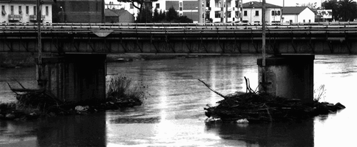
Piers are important elements of a bridge structure and their damage attracts awareness to civil engineers and bridge designers. Bridge pier failures are triggered either by floods or by debris accumulation in front of bridge piers. shows a wood debris accumulation at the railway bridge of Arno River in Pisa.
Figure 1 Debris accumulation at bridge piers of Arno River in Pisa, Italy
An example of the high damage capacity of floods on bridge piers was evidenced by the 1993 Upper Mississippi river basin floods (Hagerty et al. Citation1995). Debris accumulation on secondary roadway bridges was one of the causes for their catastrophic collapse. The effect of debris accumulation in front of bridge piers on the scour processes was considered, for example, by Laursen and Toch Citation(1956). A debris accumulation was found to generally increase scour. However, buried debris around a pier base tends to reduce the scour depth.
Specific studies on the scour process related to bridge pier debris accumulation have been conducted by Melville and Dongol Citation(1992). They made a series of experimental tests using a cylindrical accumulation extending downstream of the bridge pier. Only the accumulation effect on equilibrium scour was observed and an experimental relationship was developed in which an equivalent bridge pier diameter was defined as
Diehl Citation(1997) concluded that one of the main causes of bridge failures in the USA was linked to debris accumulation. Kattell and Eriksson Citation(1998) also considered that debris build-up is a common problem for bridge scour, causing
Equation(1) contractions, thereby reducing waterway width, Equation(2)
local scour, increasing the obstruction due to sediment accumulation, Equation(3)
angle of attack deflection increasing local scour around the bridge and
Equation(4)
debris accumulation overloading bridge discharge capacity. Parola et al.
Citation(1998) and Mueller and Parola Citation(1998) measured the field pier scour in the presence of debris accumulation, whereas Parola et al.
Citation(2000) focused on the hydrodynamic forces due to debris accumulation, which was characterized by various shapes, accumulation roughness and accumulation porosity. The hydrodynamic forces were found to depend on the blockage ratio and the debris porosity.
Richardson and Davis Citation(2001) provided a qualitative analysis on the scour evaluation at bridge piers. The scour depth in the presence of debris accumulation was evaluated assuming that the bridge pier diameter equals the debris accumulation diameter. Bradley et al. Citation(2005) studied the effect of debris impact on hydraulic structures. Briaud et al. Citation(2006) and Zevenbergen et al. Citation(2006) carried out field tests on the typical accumulation shape and sizes of bridge piers.
The temporal evolution of the maximum scour depth at bridge piers without debris accumulation was systematically investigated in the past years. A definition of the equilibrium scour is complex (Franzetti et al. Citation1989, Kothyari et al. Citation1992, Dey Citation1999, Melville and Chiew Citation1999, Zevenbergen Citation2000, Oliveto and Hager Citation2002, Chang et al. Citation2004, Hager et al. Citation2004, Dey and Barbhuiya Citation2005, Oliveto and Hager Citation2005, Raikar and Dey Citation2008). Currently, only limited information on the effect of debris accumulation on the temporal scour evolution is available. This research aims to analyse the effect of bridge pier debris accumulation on the scour process for clear-water conditions.
2 Experimental facilities
2.1 Flume characteristics
The test channel was 7.6 m long, 0.61 m wide and 0.5 m deep, provided with glass and steel walls. Discharges of up to Q = 100 l/s were measured by means of a KROHNE® Optiflux 2000 electromagnetic flow sensor. The discharge was supplied by means of a sluice gate provided with a flow straightener (0.25 cm mesh). A false bottom 2 m long, 0.15 m deep and 0.6 m wide was used to insert the pier base and the bed material. An upstream steel box 1.6 m long, 0.6 m wide and 0.15 m deep provided the transition between the scoured zone and the inlet sluice gate. The steel box was 1.20 m distant from the inlet gate. Downstream, a second box 0.8 m long, 0.6 m wide and 0.15 m deep closed the false bottom. A plexiglass cylindrical pier of diameter D = 0.03 m was used in the tests. A weir at the channel end regulated the flow depth.
2.2 Tested material
A medium river sand material S1 was used in the tests, whose granulometric characteristics are reported in . Therein, d xx is the diameter for which the xx percent in weight of material is finer, σ = (d 84/d 16)0.5the sediment standard deviation, ϕ and ϕ′ the dry and wet sediment angle of repose and Δ = (ρ s −ρ)/ρ the relative sediment density, where ρ s is the sediment density and ρ the water density. According to Raudkivi and Ettema Citation(1983), Melville and Chiew Citation(1999) and Oliveto and Hager Citation(2005), sediment size of d 50 > 0.9 mm avoids the formation of bed forms and cohesive sediment effects. According to Raudkivi and Ettema Citation(1985), the armouring effect is negligible for σ < 1.3.
Table 1 Sediment characteristics of the tested material
Based on the sediment characteristics, the sediment entrainment velocity U c was evaluated based on Wu and Wang Citation(1999) to evaluate the Shields parameter Θ. The energy line slope was evaluated using Manning's formula with a Strickler coefficient n = 0.047d 50 1/6. Tests without piers were made and visual observation of the entrainment velocity indicated a good agreement with the equation of Wu and Wang Citation(1999).
2.3 Debris accumulation
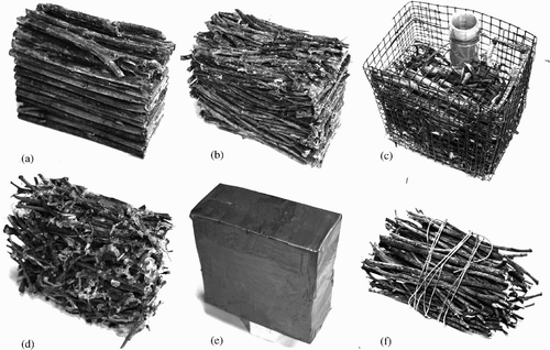
Three debris roughnesses, characterized by a smooth surface or two different natural log distributions, were tested. The tested log sizes relate to d f = 0.63 and 1.06 cm, where d f is the average log size. Logs were measured by means of a vernier caliper to ±0.1 mm.
Relative debris roughness is defined as the ratio between the log average diameter and the debris pier diameter d f /D. Tested relative roughness corresponds to d f /D ≈ 0 for smooth debris accumulation, comparable to ice or woody debris accumulation with a high presence of leaves and mud, d f /D ≈ 0.21 as medium-size log accumulation and d f /D ≈ 0.35 corresponding to coarse log accumulation. The smooth debris was simulated by means of synthetic material. To reduce surface roughness, the debris was covered with smooth plastic tape (. Rough accumulations in turn were composed of an impervious synthetic core, covered by two layers of woody logs (,). The debris logs were always glued parallel to each other and disposed normal to the flow. To verify debris permeability, two different pervious debris were used. A first roughness and pervious conditions were obtained by embedding the woody logs into a metallic cage (. The second pervious debris was made connecting the logs with a simple metallic string (. A third pervious log accumulation was tested to verify a random debris accumulation, using logs with random disposition (. In this case, the logs were glued, providing less porosity when compared with type f.
Figure 2 Tested debris accumulation of different roughness (a) type a: impervious parallel disposition, (b) type b: impervious quasi-parallel disposition, (c) type c: pervious accumulation with metal cage, (d) type d: pervious random disposition, (e) type e: smooth impervious accumulation, (f) type f: pervious quasi-parallel disposition
reports the average characteristics of the tested debris accumulation, where l d is the debris length and n d the debris porosity, defined as the ratio between the debris void volume and the bulk debris volume. The average debris roughness ϵ has been evaluated as the mean of the surface macro-roughness due to the external logs (.
Table 2 Geometric characteristics of tested debris accumulation
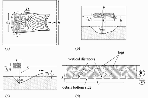
Figure 3 Sketch with rough debris accumulation (a) top view, (b) frontal view, (c) side view and (d) roughness definitions
The average geometric roughness ϵ depends linearly on the average log diameter (ϵ ≅ 1.3d f ) in the test range. Moreover, the random disposition slightly differs from the parallel disposition, but the log disposition effect is neglected. The geometric surface roughness ϵ is larger than d f because natural logs are twisted and interweaved providing a higher surface roughness than the element half-diameter. Notwithstanding, the average log size d f can be used to characterize the debris accumulation roughness. In prototypes, the log size is deduced from the riverbank or riparian vegetation average sizes and should be preferred for design applications. Therefore, for the accumulation type c, the equivalent log diameter was derived by the previous linear regression resulting in ϵ/1.3 = d f = 0.8 cm.
2.4 Experimental procedure
For each test, the bed was carefully levelled. To modify the percentage blockage ratio ΔA = [(d d −D)t d ]/(b·h)·100, where b is the channel width, the debris was fixed at various distances from the bed. For rough debris, the dimensions are defined by the equivalent parallelepiped normal to the flow containing the logs. Once the debris was fixed to the pier, the channel was slowly filled up with water until reaching a prefixed value. Successively, the test discharge Q was set, while the water level was regulated to maintain the fixed level. Once all conditions were stable, the water level was carefully adjusted to reach the prefixed flow depth h. Time started when the water level was equal to the prefixed flow depth h. Scour depths near the pier were surveyed by means of a ±0.5 mm precise clear scale glued directly on the pier. The scale was glued on both sides to control scour symmetry. The end scour depth and the final scour profiles were also surveyed by means of a point gauge ±0.1 mm precise. For each test, measurements were taken at t = 1, 2, 4, 8, 15, 30, 60, …, 360, …, min. To check the temporal effect, the tests generally lasted for 360 min. Long tests, up to 96 h, were also conducted.
shows a sketch of the test facility, where h is the approach flow depth, z max the maximum scour depth and z M the maximum dune height. In , DB is the debris bottom elevation, defined as the plane tangent to the logs, ϵ the debris roughness, defined as the average vertical distance from DB and the logs and RL the roughness level whose distance is ϵ from DB. The unobstructed section was defined as the section for which the pier obstruction does not affect the surface profile. Surface profile indicated a 1 mm order difference between the unobstructed and the pier sections, for either debris accumulations or isolated piers. Thus, the backwater effect was neglected.
According to Oliveto et al. Citation(2004), maximum scour depths z max measured with the graduated scale glued on the pier have smaller values when compared with the maximum scour depth ž max measured with a point gauge at ≈ 0.75D from the pier centre. Differences between the two at the test end were generally less than 10%, corresponding to a 0.3–0.4 cm maximum scour under-prediction. However, glued scale measurements were preferred to evaluate the maximum scour temporal evolution, to reduce any disturbance due to gauge presence and its interaction with the bed.
3 Experimental results
3.1 General
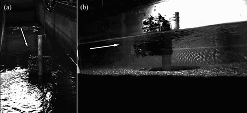
More than 70 tests were conducted either with smooth or with rough debris in various hydraulic conditions. Several variables affect the scour evolution. The analysis below focuses on the effect of debris geometry (thickness t d , diameter d d ), debris roughness and its porosity. From preliminary tests, the maximum effect on scour was a debris length l d ≈ 2.5D, which then was held constant. To reduce the variables affecting scour, the debris width was fixed to d d ≈ 5.67D. According to Raudkivi and Ettema Citation(1983) and Melville Citation(1997), the effect of relative sediment size D/d 50 affects the scour process between 25 < D/d 50 < 50. Nonetheless, this effect was neglected, and all tests were carried out for D/d 50 = 30. Hydraulic conditions strongly affect the scour process, such as the relative shallowness and discharge (Melville and Chiew Citation1999, Kandasamy and Melville Citation1998). Thus, the relative shallowness varied between 2.67 < h/D < 5.67 and the flow intensities between 0.65 < U/U c < 1, where U is the approach flow velocity corresponding to flow depth h. shows photos of a test with wood debris accumulation. Note the influence on the wake vortex due to debris accumulation (. Despite this accumulation, the up- and downstream surface profiles only slightly differ, indicating a negligible backwater effect (.
Figure 4 Test with rough debris accumulation (d f /D = 0.21, h/D = 5.67, U/U c = 1): (a) downstream view, (b) side view with scour formation
3.2 Temporal pier scour evolution in presence of debris accumulation
According to Melville and Chiew Citation(1999), the temporal scour evolution without debris accumulation varies with the flow shallowness h/D, flow intensity U/U c , sediment coarseness d 50/D and non-dimensional time T = Ut/D (Franzetti et al. Citation1994). Since the debris accumulation strongly affects the scour process, additional debris parameters must be added, i.e., t d , d d , d f and n d . Therefore, the temporal scour evolution is a function of z max /D = f(U/U c , h/D, d 50/D, T, ΔA, d d /D, d f /D, n d ). The non-dimensional time parameter without debris accumulation can be considered a function of the area contracted by the piers, i.e. T = hUt/(h·D). Therefore, a new parameter was defined as T* = hUt/A acc , where A acc = (d d −D) t d + hD, to account for the accumulation effect by both the bridge pier and the debris accumulation on the temporal scour evolution. For constant d d /D and neglecting the coarseness effect, the resulting relationship is z max /D = f(U/U c , h/D, T*, ΔA, d f /D, n d ).
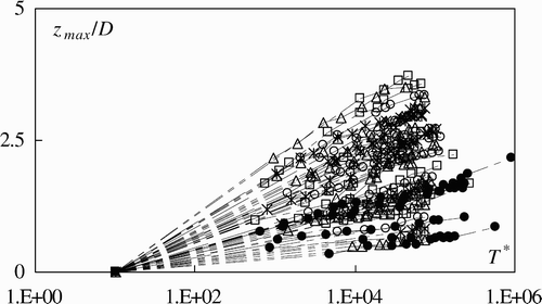
shows the scour evolution data near the pier in presence of debris accumulation. Data with relative roughness 0 < d f /D < 0.35 were plotted for both pervious and impervious debris accumulations, flow intensities in the range of 0.65 < U/U c < 1 and blockage ratios between 5.4 < ΔA < 12.1. For T* < 106, the temporal evolution generally has a single slope in semi-log scales. The effect of debris accumulation on scour evolution is evident. Tests with debris accumulation generally result in larger scour depth. According to Melville and Dongol Citation(1992), the maximum equilibrium scour depth with debris accumulation is 1.49 times larger than the maximum equilibrium scour depth without debris accumulation. According to the present test results, the presence of debris can increase the scour depth up to two to three times that without accumulation, provided ΔA < 12.1.
Figure 5 Non-dimensional scour evolution for various roughness conditions for (•) tests without accumulation, (□) d f /D = 0, n d = 0; (○) d f /D = 0.21 n d = 0; (▵) d f /D = 0.35 and n d = 0; (*) d f /D = 0.21 and n d = 0.6; (+) d f /D = 0.21 and n d = 0.7
Kothyari et al. Citation(1992) and Oliveto and Hager Citation(2002) observed a logarithmic law for scour evolution. Therefore, the temporal parameter ξ(U/U c , h/D, ΔA, d f /D, n d ) was calculated for each test, using a simple standard regression as
3.3 Debris roughness influence
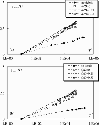
shows the temporal scour evolution for various debris roughness conditions ranging 0 < d f /D < 0.35. relates to U/U c = 0.83, h/D = 2.67 and ΔA = 12.1. The high contraction operated by the debris accumulation significantly affects scour evolution reaching a value of up to 2.12 times the scour depth without accumulation. The debris roughness tends to further increase the scour depth by 20% from d f /D = 0 to d f /D = 0.35. shows the test data for U/U c = 0.84, h/D = 5.67, ΔA = 12.1. Also for higher h/D, the contraction effect is evident. High roughness (d f /D = 0.35) increases the scour depth up to 1.2 times that with a smooth debris accumulation (.
Figure 6 Temporal scour evolution for U/U c = 0.83, ΔA = 12.1 and (a) h/D = 2.67, (b) h/D = 5.67
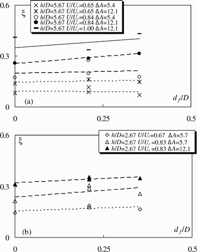
shows the effect of debris roughness for various accumulations on the temporal evolution coefficient ξ versus d f /D, indicating an increase in the temporal scour evolution with the accumulation roughness. Generally, the roughness effect is more prominent for high contraction and high flow intensities. The roughness, however, only slightly affects the scour evolution for low contractions and flow intensities. This effect is also present in shallow waters (.
Figure 7 Effect of accumulation roughness d f /D on ξ for various test conditions
From a hydrodynamic point of view, the presence of debris accumulation behaves as an obstacle developing a new boundary layer below the accumulation itself. The obstacle roughness strongly affects the boundary layer thickness, the log velocity profile shift and the Reynolds stresses under the rough debris accumulation (Krogstad et al. Citation1992, Balachandar and Patel Citation2002, Bergstrom et al. Citation2002, Balachandar and Blakely Citation2004). From small to high debris roughness surface, the boundary layer thickness increases and the log velocity profile shifts towards the bed. The presence of contraction due to debris and the consequent shift of the velocity field towards the pier bottom increases the shear stress, the turbulent burst sediment lift action in the pier wake region and, thus, the scour magnitude. Moreover, the field observation carried out by means of coloured tracers indicated that the boundary layer below the accumulation develops an upward vortex in correspondence with the stagnation bridge pier section, further affecting the flow field.
3.4 Debris porosity influence
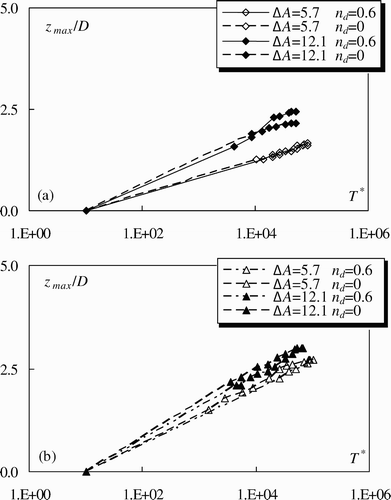
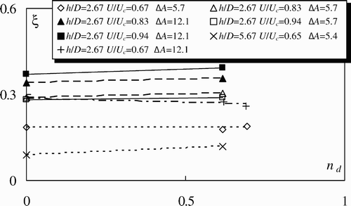
According to Parola et al. Citation(2000), the porosity of the debris was found as one of the most relevant variable affecting the overload of bridge piers due to debris accumulations. Therefore, the porosity effect on the scour evolution was analysed for various flow magnitudes, blockage ratios and flow depths. shows the temporal scour evolution for h/D = 2.67, 0 < n d < 0.6, 5.7 < ΔA < 12.1 and 0.67 < U/U c < 0.84. In both plots, the greater the blockage ratio ΔA was, the higher was the temporal scour evolution, thus confirming its importance. Likewise, the greater the flow intensity, the deeper was the scour hole, while porosity had only a small effect.
Figure 8 Effect of accumulation porosity on scour evolution for h/D = 2.67 and d f /D = 0.21 for (a) U/U c = 0.67, (b) U/U c = 0.84
shows the coefficient ξ against n d for various test conditions. Although the wide porosity ranges, its effect seems negligible in either deep water or near the threshold condition. Note that the geometric roughness was not exactly the same for the tested pervious or impervious debris. Tests with n d = 0 were made using the parallel disposition (type b), while tests with n d = 0.6 were made with type d, of geometrical roughness ϵ = 0.8 and 0.89 cm, respectively.
Figure 9 Effect of accumulation porosity on ξ for various accumulation porosities and d f /D = 0.21
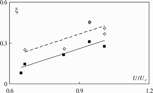
3.5 End scour prediction
shows ξ(U/U c ) for 5.4 < ΔA < 12.1, 2.67 < h/D < 5.67 and d f /D = 0. For given ΔA and h/D, ξ has a monotonic dependence on U/U c in the range of 0.65 < U/U c < 1. The results are consistent with previous findings for which the temporal scour depth evolution increases with the flow intensity up to the threshold value (U/U c = 1) (Oliveto and Hager Citation2002). Moreover, the blockage ratio ΔA significantly affects ξ. The larger the blockage ratio, the higher is the temporal scour depth, with the data indicating constant differences from low to high blockage ratios.
Figure 10 Curve ξ(U/U c ) for 2.67 < h/D < 5.67 and 5.4 < ΔA < 5.7, (▪) data, (―) regression line, and 2.67 < h/D < 5.67 and ΔA = 12.1, (▵) data, (––) regression line
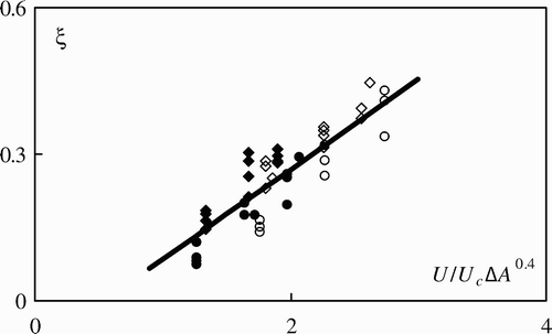
To account for the effect of ΔA on ξ, the data were plotted versus a new variable U/U c ΔA β, where coefficient β was fitted to all the data. For a given β, the temporal evolution coefficient was then linearly interpolated as
Figure 11 Dependence of ξ from the flow intensity and blockage ratio (R 2 = 0.73) for (♦) h/D = 2.67 and ΔA = 5.7, (⋄) h/D = 2.67 and ΔA = 12.1, (•) h/D = 5.67 and ΔA = 5.4, (○) h/D = 5.67 and ΔA = 12.1
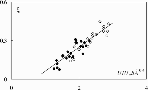
Notwithstanding, the fictitious variable (t d + d f ) explains the scour increases due to the roughness effect. shows the data for the percentage rough blockage ratio ΔÃ = [(d d –D)·(t d + d f )]/(b·h)·100. The roughness tends to increase the scour depth, thus the use of the new variable virtually increases the size of the debris accumulation, although the tested blockage ratio ΔA was kept constant for identical flow intensity and water shallowness. The use of ΔÃ increases R 2 from 0.73 to 0.80, providing a better variable ΔÃ and includes the debris roughness effect on bridge scour.
Figure 12 Dependence of ξ(U/U c ΔÃ 0.4) for (♦) h/D = 2.67 and ΔA = 5.7, (⋄) h/D = 2.67 and ΔA = 12.1, (•) h/D = 5.67 and ΔA = 5.4, (○) h/D = 5.67 and ΔA = 12.1
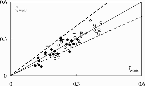
Accordingly, the temporal evolution coefficient is
Figure 13 Comparison between measured ξ data and data calculated from
EquationEq. (4). Symbols as in for (–) type c data with 0.67 < U/U
c
< 1, 2.67 < h/D < 5.67, 5.4 < ΔA < 12.1, d
f
/D = 0.26. (―) Perfect agreement, (––) ±25% deviation
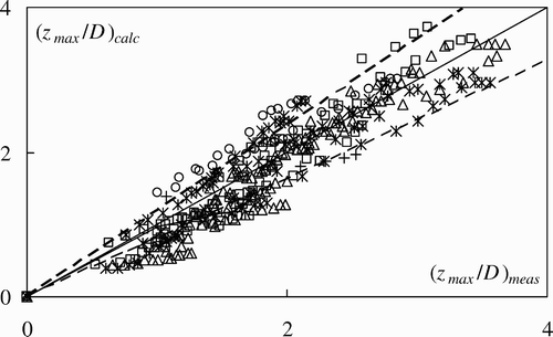
shows the temporal scour evolution using
EquationEq. (4) for various tested areas, debris roughness, flow shallowness and flow intensities. The plot substantially shows a good agreement with
EquationEq. (4)
, though some tests with high roughness and zero porosity are slightly under-predicted.
Figure 14 Comparison between measured and calculated non-dimensional scour depths (Eq. 4) for various roughness and (□) d f /D = 0, n d = 0; (○) d f /D = 0.21, n d = 0; (▵) d f /D = 0.35, n d = 0; (*) d f /D = 0.21, n d = 0.6; (+) d f /D = 0.21, n d = 0.7. (―) Perfect agreement and (––) ±25% deviation
3.6 Debris roughness and porosity influence on scour geometry
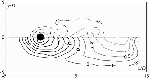
The scour hole morphology in the presence of the bridge pier is similarly affected by debris accumulation as is the maximum scour depth. shows the non-dimensional scour depth z/D contour lines measured at the test end, where z is the vertical scour depth for tests without and with accumulation, i.e. U/U c = 1.0, h/D = 5.67, ΔA = 0 (dashed lines), and U/U c = 1.0, h/D = 5.67, ΔA = 12.1 (solid lines). The comparison relates to the streamwise symmetry axis, x is the streamwise coordinate with respect to the pier centre and y the transverse coordinate with respect to the pier centre. In the presence of the debris accumulation, the scoured material tends to be transported far downstream from the bridge piers, and the maximum dune height is higher when compared with that in the absence of debris accumulation. The dune morphology has similar shapes in both cases, with the extreme dune tips propagating far downstream relative to the maximum dune height, having a typical swallow-tail shape.
Figure 15 Non-dimensional end scour z/D contour lines for U/U c = 1, h/D = 5.67, and (···) ΔA = 0 and U/U c = 1, h/D = 5.67, (―) ΔA = 12.1, (––) symmetry axis
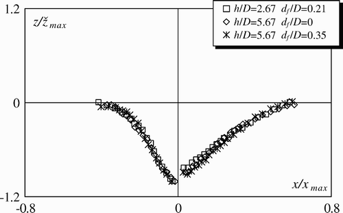
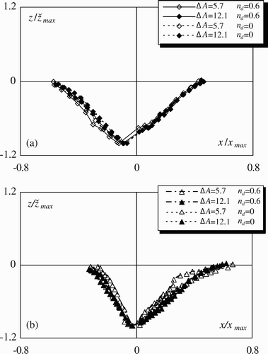
shows the non-dimensional end scour profile for 0 < d f /D < 0.35, 2.67 < h/D < 5.67, constant blockage ratio ΔA = 12.1 and U/U c = 0.84. The vertical scour depth z and the longitudinal coordinate x were related to the maximum measured scour depth ž max and the maximum scour hole length x max . The reference system is located at the centre of the bridge pier. Note that roughness does not affect the non-dimensional scour hole shape. For identical flow intensity, the shallowness influence is therefore negligible.
Figure 16 Non-dimensional scour hole profile z/ž max (x/x max ) for 0.83 < U/U c < 0.84 and ΔA = 12.1
shows the non-dimensional end scour hole profile. Although the tests with high porosity (n d = 0.6) and low blockage ratio ( slightly differ from the remainder, the non-dimensional profiles are similar and the effect of the porosity is small for both high and low flow intensities.
Figure 17 Non-dimensional scour profiles z/ž max (x/x max ) for h/D = 2.67, d f /D = 0.21 and (a) U/U c = 0.67 and (b) U/U c = 0.84
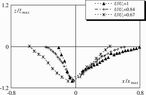
shows the effect of flow intensity on the scour hole profile. Low intensity flows (U/U c = 0.67) have a longer upstream scour profile up to x/x max = −0.57, while intermediate intensity flows are steeper and shorter (x/x max = −0.35). The maximum flow intensity generates the closest value (x/x max = −0.20). For intermediate and high flow intensities (0.84 < U/U c < 1), the scour profile has a larger downstream extension to x/x max = 0.63 and 0.80, respectively, because of the higher sediment transport capacity, while that of low intensity flows ends at x/x max = 0.54).
Figure 18 Non-dimensional scour profiles z/ž max (x/x max ) for h/D = 5.67, d f /D = 0, ΔA = 12.1 and 0.67 < U/U c < 1
4 Conclusions
This work presents an experimental analysis on the effect of debris accumulation at bridge piers and the related scour evolution. The accumulations were characterized by several log diameters, debris roughness and porosity. Flow intensities and blockage ratio were also tested. Experimentation and the data analysis evidenced the following:
-
Scour depth in the presence of debris accumulation can raise up to three times that without debris accumulation.
-
Main parameters affecting the temporal scour evolution are flow intensity and blockage ratio.
-
Porosity effect is negligible in terms of scour hole geometry, although porosity is important when evaluating the hydrodynamic overload of bridge piers.
-
Relative roughness of debris has a direct effect on bridge scour. The average log diameter successfully describes the blockage ratio.
-
Scour hole shape is not affected by the relative debris roughness, while the non-dimensional scour hole shape depends mainly on the flow intensity.
Notation
| a, b = | = |
regression coefficients |
| A acc = | = |
accumulated area |
| b = | = |
channel width |
| D = | = |
pier diameter |
| D e = | = |
equivalent debris diameter |
| d = | = |
particle size |
| d d = | = |
debris width |
| d f = | = |
average debris log diameter |
| h = | = |
approach flow depth |
| l d = | = |
debris length |
| n = | = |
Manning's coefficient |
| n d = | = |
debris porosity |
| Q = | = |
discharge |
| R 2 = | = |
determination coefficient |
| T = | = |
non-dimensional time |
| T* = | = |
non-dimensional time relative to A acc |
| t = | = |
time |
| t d = | = |
debris thickness |
| t d + d f = | = |
rough debris thickness |
| U = | = |
approach flow velocity |
| U c = | = |
critical flow velocity |
| x = | = |
longitudinal coordinate |
| y = | = |
transversal coordinate |
| x max = | = |
maximum scour length |
| z = | = |
vertical coordinate |
| z M = | = |
maximum dune height |
| ž max = | = |
maximum scour depth at the maximum scour section |
| z max = | = |
maximum scour depth near pier |
| β = | = |
regression coefficient |
| Δ = | = |
(ρ s −ρ)/ρ = relative sediment density |
| ΔÃ = | = |
[(d d −D)·(t d + d f )]/(b·h)·100 = percentage rough blockage ratio |
| ΔA = | = |
[(d d −D)t d ]/(b·h)·100 = percentage blockage ratio |
| ϵ = | = |
average debris roughness |
| ξ = | = |
temporal evolution coefficient |
| Θ = | = |
Shields' critical parameter |
| ρ = | = |
water density |
| ρ s = | = |
sediment density |
| σ = | = |
sediment uniformity |
| ϕ and ϕ′ = | = |
dry and wet sediment angles of repose |
Related Research Data
References
- Balachandar , R. and Patel , V. C. 2002 . Rough wall boundary layer on plates in open channels . J. Hydraul. Eng. , 128 ( 10 ) : 947 – 951 .
- Balachandar , R. and Blakely , D. 2004 . Surface roughness effects on turbulent boundary layers on a flat plate located in an open channel . J. Hydraulic Res. , 42 ( 3 ) : 247 – 261 .
- Bergstrom , D. J. , Kotey , N. A. and Tachie , M. F. 2002 . The effects of surface roughness on the mean velocity profile in a turbulent boundary layer . J. Fluids Eng , 124 ( 3 ) : 664 – 670 .
- Bradley , J. B. , Richards , D. L. and Bahner , C. D. 2005 . “ Debris control structures: Evaluation and countermeasures ” . Washington, DC : Federal Highway Administration . Report No. FHWA-IF-04-016, Hydraulic Engineering Circular No. 9, 3rd ed
- Briaud , J. L. , Chen , H. C. , Chang , K. A. , Chen , X. and Oh , S. J. Scour at bridges due to debris accumulation: A review . Proc. 3rd Intl. Conf. Scour Erosion . Amsterdam, NL. (CD-ROM)
- Chang , W. Y. , Lai , J. S. and Yen , C. L. 2004 . Evolution of scour depth at circular bridge piers . J. Hydraul. Eng. , 130 ( 9 ) : 905 – 913 .
- Dey , S. 1999 . Time-variation of scour in the vicinity of circular piers . Proc. Instn Civil Engrs Water, Marit. Energy , 136 ( 2 ) : 67 – 75 .
- Dey , S. and Barbhuiya , A. K. 2005 . Time variation of scour at abutments . J. Hydraul. Eng. , 131 ( 1 ) : 11 – 23 .
- Diehl , T. H. 1997 . “ Potential drift accumulation at bridges ” . In Publication No. FHWA–RD–97–028 , Washington, DC : Federal Highway Administration .
- Franzetti , S. , Larcan , E. and Mignosa , P. 1989 . Erosione alla base di pile circolari di ponte: Verifica sperimentale dell'ipotesi di esistenza di una situazione finale di equilibrio . Idrotecnica , 16 ( 3 ) : 135 – 141 . [in Italian]
- Franzetti , S. , Malavasi , S. and Piccinin , C. Sull'erosione alla base delle pile di ponte in acque chiare . 14th Convegno Idraulica e Costruzioni Idrauliche . Naples Italy 4, 13–24, [in Italian]
- Hager, W.H., Oliveto, G., Pagliara, S., Unger, J. (2004). Recent advances in scour hydraulics. River Flow 2004, Greco, Carravetta, and Della Morte (eds), Taylor & Francis, London, 1, 3–12.
- Hagerty , D. J. , Parola , A. C. and Fenske , T. E. 1995 . “ Impacts of 1993 Upper Mississippi river basin floods on highway systems ” . In Report No. 1483 , Washington, DC : Transportation Research Board .
- Kandasamy , J. K. and Melville , B. W. 1998 . Maximum local scour depth at bridge piers and abutments . J. Hydraulic Res. , 36 ( 2 ) : 183 – 198 .
- Kattell , J. and Eriksson , M. 1998 . “ Bridge scour evaluation: Screening, analysis and countermeasures ” . In Gen. Tech. Rep. 9877 1207–SDTDC , San Dimas, CA : U.S. Department of Agriculture, Forest Service .
- Kothyari , U. C. , Garde , R. J. and Ranga Raju , K. G. 1992 . Temporal variation of scour around circular bridge piers . J. Hydraul. Eng. , 118 ( 8 ) : 1091 – 1106 .
- Krogstad , P. A. , Antonia , R. A. and Browne , L. W.B. 1992 . Comparison between rough- and smooth-wall turbulent boundary layers . J. Fluid Mech , 245 ( 9 ) : 599 – 617 .
- Laursen , E. M. and Toch , A. 1956 . “ Scour around bridge piers and abutments ” . In Bulletin No. 4 , Ames, IA : Iowa Highway Research Board .
- Melville , B. W. 1997 . Pier and abutment scour: Integrated approach . J. Hydraul. Eng. , 123 ( 2 ) : 125 – 136 .
- Melville , B. W. and Chiew , Y. M. 1999 . Time scale for local scour at bridge piers . J. Hydraul. Eng. , 125 ( 1 ) : 59 – 65 .
- Melville , B. W. and Dongol , D. M. 1992 . Bridge pier scour with debris accumulation . J. Hydraul. Eng. , 118 ( 9 ) : 1306 – 1310 .
- Mueller , D. S. and Parola , A. C. Detailed scour measurements around a debris accumulation . Proc. Water Resources Engng. Conf . pp. 234 – 239 . Reston, VA : ASCE .
- Oliveto , G. and Hager , W. H. 2002 . Temporal evolution of clear-water pier and abutment scour . J. Hydraul. Eng. , 128 ( 9 ) : 811 – 820 .
- Oliveto , G. and Hager , W. H. 2005 . Further results to time-dependent local scour at bridge elements . J. Hydraul. Eng. , 131 ( 2 ) : 97 – 105 .
- Oliveto , G. , Unger , J. and Hager , W. H. 2004 . Discussion of Design method of time-dependent local scour at circular bridge pier . J. Hydraul. Eng. , 130 ( 12 ) : 1211 – 1213 .
- Pagliara , S. , Hager , W. H. and Unger , J. 2008 . Temporal evolution of plunge pool scour . J. Hydraul. Eng. , 134 ( 11 ) : 1630 – 1638 .
- Parola , A. C. , Apelt , C. J. and Jempson , M. A. 2000 . “ Debris forces on highway bridges ” . In NCHRP Report No. 445 , Washington, DC : Transportation Research Board .
- Parola , A. C. , Kamojjala , S. , Richardson , J. and Kirby , M. Numerical simulation of flow patterns at a bridge with debris . Water Resources Engng. Conf . pp. 240 – 245 . Reston, VA : ASCE .
- Raikar , R. V. and Dey , S. 2008 . Kinematics of horseshoe vortex development in an evolving scour hole at a square cylinder . J. Hydraulic Res. , 46 ( 2 ) : 247 – 264 .
- Raudkivi , A. J. and Ettema , R. 1983 . Clear-water scour at cylindrical piers . J. Hydraul. Eng. , 109 ( 3 ) : 338 – 350 .
- Raudkivi , A. J. and Ettema , R. 1985 . Scour at cylindrical bridge piers in armored beds . J. Hydraul. Eng. , 111 ( 4 ) : 713 – 731 .
- Richardson , E. V. and Davis , S. R. 2001 . “ Evaluating scour at bridges ” . In Report No. FHWA–NHI–01–001, Hydraulic Engineering Circular No. 18, 4th , Washington, DC : Federal Highway Administration .
- Wu , W. and Wang , S. S.Y. 1999 . Movable bed roughness in alluvial rivers . J. Hydraul. Eng. , 125 ( 12 ) : 1309 – 1312 .
- Zevenbergen , L. W. 2000 . Time scale for contraction scour at bridges . J. Water Res. Plan. Manage , 104 ( 3 ) : 405 – 410 .
- Zevenbergen , L. W. , Lagasse , P. F. , Clopper , P. E. and Spitz , W. J. Effects of debris on bridge pier scour . 3rd Intl. Conf. Scour Erosion . Amsterdam, NL (CD-ROM)