Abstract
There are many studies on the flow movement in compound channels, yet few are concerned with sediment transport. An experimental study on the flow movement and sediment transport in compound channels is presented. The experimental results indicate that the distribution of longitudinal velocity with depth in the main channel and the floodplains has a logarithmic component. The longitudinal velocity with flow depth in the interactive region does not obey a logarithmic distribution, but involves a wake function. In the boundary region, the longitudinal velocity obeys a parabolic distribution. In addition, based on the suspended sediment diffusion equation and the flow interaction between main channel and floodplains, expressions are derived to predict the lateral eddy viscosity and the sediment diffusion coefficients. Finally, an analytical solution for the lateral distribution of the depth-averaged velocity and sediment concentration in a compound channel is obtained. The results from the analytical solution agree well with experimentation.
1 Introduction
Overbank flow is a common phenomenon in fluvial rivers. If the discharge is small, flow runs in the main channel, while the flow enters the floodplains otherwise. The flow characteristics of compound channels, such as the flow conveying capacity, flow structure and distribution of sediment concentration, have been studied since the 1970s. Myers Citation(1978), Wormleaton et al. Citation(1982), and Prinos and Townsend Citation(1984) considered the discharge calculated using the “single channel”-method which was found 16–40% smaller than from observations, and that the error gradually increases with the resistance in the main channel and floodplain. Prinos and Townsend Citation(1984), Ervine and Baird Citation(1982), and Wormleaton and Merrett Citation(1990) suggested that the main channel and floodplain should be treated separately. The total discharge was calculated by summing the discharges of the various subsections. The estimated discharge is more accurate if the apparent shear stress between the main channel and floodplain is considered (Fukuhara and Murota Citation1990). Tominaga et al. (1991, Citation1993) analysed the turbulence intensity at the interface of the main channel and floodplain under different roughness and depth conditions. Knight and Shiono Citation(1990) proposed experimental formulas to estimate the turbulence intensity. Myers Citation(1978) suggested that the momentum transfer from channel to floodplain can be taken as an apparent shear force, and its maximum value may reach 25% of the weight of the main channel water component. Experiments conducted by Tominaga and Nezu Citation(1991) and Rajaratnam and Ahmadi Citation(1981) indicated that the maximum bed shear stresses in the main channel and floodplains are near the centre and their interface, respectively. Compared with a single channel, the shear stress in a compound channel decreases in the main channel but increases in the floodplain (Myers and Elsawy Citation1975, Myers Citation1978).
Rhodes and Knight Citation(1994), Rajaratnam and Ahmadi Citation(1981), and Ji Citation(1997) recorded the flow velocity. They deduced that the vertical velocity distribution is deformed by momentum transfer, and an obvious departure from the logarithmic law was observed in both the main channel and the floodplain. Xie Citation(1980), Zhou Citation(1995), Ji Citation(1997), and Shiono and Knight Citation(1991) presented analytical results on the transverse distribution of the depth-averaged velocity according to the kinetic flow equation. James Citation(1985) and Liu Citation(1991) simulated the distribution of sediment concentration using numerical models. Many results for the flow movement are currently available, but few works of research on sediment transport in compound channels can be found. This research generalizes the river reaches into two types: straight and the lotus-root-shape compound channels that describe common natural fluvial rivers for which experiments on the flow movement and the sediment transport are conducted.
2 Experimental methodology
2.1 Experimental conditions
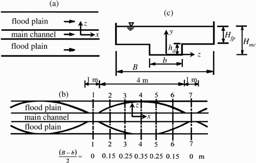
In this research, the generalized physical model includes straight and lotus-root-shape models 30 m in length. A self-circulating structure was adopted in the model, and both sides and beds were fixed with smooth cement. The values of Manning roughness coefficients for the main channel and the floodplains were 0.011 and 0.013 s/m1/3, respectively. The symmetrical cross-sections consist of one channel and two floodplains, and the bed slope was 0.001. For the straight channel, the width of the main channel was b = 0.3 m and the width of the floodplain (B – b)/2 = 0.35 m. Here B is the width of compound channel. The height difference between the channel and floodplain was h d = 0.06 m. For the lotus-root-shape channel, b = 0.3 m; however, (B – b)/2 changes from 0 to 0.35 m. The length of each lotus-root-shape reach is 4 m. There is a 1 m transitional reach between each lotus-root-shape reach (). Data were collected in seven cross-sections in a lotus-root-shape reach, but only the fourth cross-section has the same dimension as the straight channel. The data from this cross-section were used as the comparison between the two channels.
Figure 1 Sketches of (a) straight and (b) lotus-root-shape compound channels, (c) compound cross section
The experimental reach is 20 m long and extends from 7 m downstream of the model inlet to 3 m upstream of the outlet. Owing to channel symmetry, the measurements were taken only for a half cross-section from the channel axis to one channel side. Ten to fifteen vertical lines, of which each line has 5–20 nodes, were used to measure velocity and sediment concentration. The cross-section for measuring velocity and sediment concentration was 18 m downstream of the inlet. Experiments were conducted in the two channels under various flow and sediment conditions. Selected experimental conditions are listed in , including discharge, flow depth, velocity, Froude number F = U/(gH)1/2, where g is the gravitational acceleration and Reynolds number R = UH/ν, where ν is the kinematic viscosity. For experiments in the straight channel, the flow and sediment conditions included the flow depth of the main channel (subscript mc) H mc = 0.025–0.127 m, the discharge and sediment concentration at the inlet, Q = 0.002–0.039 m3/s and S = 4–83 kg/m3, respectively. For experiments in the lotus-root-shape channel, H mc = 0.030–0.122 m, Q = 0.009–0.022 m3/s, and suspended sediment concentration was S = 4–25 kg/m3. Ash from burnt coal was used as model sand, with a median diameter of d 50 = 1.4×10⁻⁵ m and specific gravity of 2100 kg/m3. The subscript “fp” used in and describes the floodplain.
Table 1 Main experimental variables
2.2 Instrumentation
Velocity measurements were undertaken with an inductive pressure measurement set. The equipment comprises a guiding-pressure system, an inductive system and a magnifying system. As the inductive probes are subjected by a flow pressure, a film resistor in the inductive probe transfers the distortion from the pressure difference into an electric signal. A steady electric pressure can be output by compensating and magnifying modes. Therefore, flow velocity can be measured depending on the calibrated linear relationship between output electric pressure and the acting flow force.
Two methods were applied to measure the sediment concentration. An ultrasonic apparatus was used for concentrations less than 15 kg/m3, otherwise pycnometers were used. The accuracy for the sediment concentration measurement was 0.1 kg/m3.
3 Analysis of experimental data
3.1 Flow conveying capacity
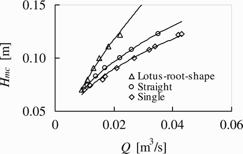
The relationships between water level and discharge in the straight and lotus-root-shape compound channels are shown in . The relationship between water level and discharge in a single channel without floodplains is also shown in , as calculated using Manning's formula by assuming identical depth and area as for the two compound channels. Because of the momentum transfer between the main channel and the floodplains, the flow conveying capacity in the straight channel is less than that in a single channel, but larger than that in the lotus-root-shape channel, with their differences increasing gradually with the flow depth. With a relative depth of floodplain to main channel H fp /H mc = 0.14–0.51, flow conveying capacities in the straight and lotus-root-shape compound channels decreased by 7–21%, and 11–48%, respectively, compared with the single channel capacity. In addition, the flow conveying capacity in the lotus-root-shape compound channel is 4–34% less than that in the straight compound channel.
3.2 Distribution of flow velocity
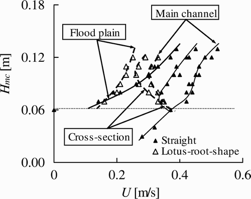
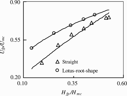
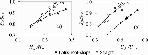
It is seen from that the tendencies of the cross-sectional mean velocity are similar for the two compound channels. With increasing depth, the mean velocities in the main channel first increase, then decrease and rise again, whereas the velocities in the floodplain continually increase. This kind of distribution indicates that momentum transfer exists between the main channel and the floodplains. The difference in distributions means that the momentum transfer is stronger in the lotus-root-shape channel than in the straight channel. The relative velocity of floodplain to channel U fp /U mc increases with relative depth H fp /H mc , and the velocities are largely different at lower relative depth, but similar at a higher relative depth, as shown in .
Distributions of depth-averaged velocity are shown in . For different depths, distributions in the two compound channels are similar, and the depth-averaged velocities decrease gradually from the central zone of the main channel to the sides of the floodplains, although some differences are observed. First, the difference between the maximum and minimum velocities and the transverse gradient of velocity near the interface are larger in the straight channel than in the lotus-root-shape channel. Second, the differences in depth-averaged velocity are obvious in the main channel zones, but the opposite is true in the floodplains.
Figure 5 Transverse distributions of depth-averaged velocity for H mc = (a) 0.09 m, (b) 0.10 m, (c) 0.11 m, and (d) 0.12 m
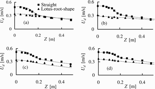
Research by Rajaratnam and Ahmadi Citation(1981), Rhodes and Knight Citation(1994), Xie Citation(1980), Zhou Citation(1995) or Shiono and Knight Citation(1991) indicates that the distributions of depth-averaged velocity have characteristics common with the present research. In general, the peak value of the momentum transfer appears near the interface of the main channel and the floodplain, where the transverse gradient of the velocity reaches a maximum. If the channel and floodplain are broad enough, a region may exist in which the transverse gradient approaches zero in the main channel and floodplain zones, and flow movement would not be affected by momentum transfer in these zones. The momentum transfer greatly affects the flow movement in the transition region between these two zones. This region is a keystone in the study of overbank flow, therefore.
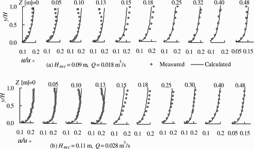
The non-dimensional velocity distributions are shown in for typical data sets. Most vertical distributions obey the logarithmic distribution law, except near the channel/floodplain interface. The distributions near this interface exhibit some distortion. At the main channel side, the locations of maximum velocity are not at the flow surface, but at a lower point. At the floodplain side, the maximum velocity is still at the water surface. The distributions obey the logarithmic law if the depth in the floodplain is less than φh. Here, coefficient φ varies between 0.5 and 1.0 in the main channel and 0.2–1.0 in the floodplain. The coefficient φ reaches a minimum at the interface, and increases gradually to a maximum from the interface to the central zones of the floodplain and the main channel. If the depth in the floodplain is larger than φh, the distributions do not obey the logarithmic law. At the side of the main channel, the measured velocities are always smaller than calculated from the logarithmic formula. On the other hand, at the floodplain side, the measured velocities are always greater than these calculated. The differences between measured and calculated velocities exhibits two characteristics: Equation(1) maximum difference in the transverse direction appears near the channel/floodplain interface and decreasing in either direction from the interface; and (2) maximum difference in the vertical direction is observed at the flow surface, and differences almost disappears if the depth is equal to φh.
3.3 Distribution of sediment concentration
For the two compound channels, the mean sediment concentration in the floodplain was smaller than in the main channel. The relationships between the relative sediment concentration S fp /S mc , the relative velocity U fp /U mc and the relative flow depth H fp /H mc are shown in . Here S fp and S mc are the sediment concentrations in the floodplain and the main channel, respectively. The relative sediment concentrations in the two compound channels increase with relative velocity and flow depth. The relative sediment concentration increases with relative depth more rapidly in the straight than in the lotus-root-shape channel. The relative sediment concentration increases with relative velocity at similar rates for the two compound channels.
Figure 7 Relationships for relative sediment concentration versus relative (a) flow depth and (b) velocity
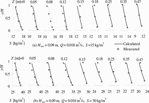
The vertical distributions of sediment concentration in the two compound channels change with the flow momentum exchange (). A distortion of the vertical distribution in the interface region between the main channel and the floodplain is apparent, and cannot be predicted by the formula of Rouse Citation(1937). The measured sediment concentrations are smaller than the calculated values in the main channel. In other regions, the distortion remains small, and the formula describes the experimental data.
Figure 8 Vertical distribution of sediment concentration compared with Rouse Citation(1937) distribution for (a) lotus-root-shape channel, (b) straight channel
Mean gradients of the sediment concentration in the vertical direction are given in . Their magnitude indicates the asymmetry in the vertical distribution. The gradients in are averages of all experimental data, namely (S b −S s )/H, where H is the flow depth in the main channel or in the floodplain, depending on the location of the measurement line, and S b and S s are the sediment concentrations at 0.1H and 0.9H, respectively. For both compound channels, the mean gradients are smaller in the lotus-root-shape than in the straight channel, and are larger on the floodplain than in the main channel, respectively.
Table 2 Averaged gradients of sediment concentration in vertical direction (kg/m3 m)
4 Theoretical analyses
4.1 Divided mode of compound cross-section
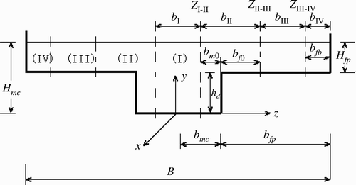
According to the flow characteristics for the two types of compound channels, the cross-section can be divided into four regions (): (I) undisturbed region of main channel (URMC), (II) interactive region between channel and plain (IRCP), (III) undisturbed region in the floodplain (URFP) and (IV) boundary region (BR). In the URMC and URFP, vertical distributions of velocity have a logarithmic component, and can be described as
4.2 Verification of logarithmic formula in IRCP
According to typical characteristics of the vertical velocity distribution, IRCP can be divided into two parts, namely the inner zone of the main channel, in which the velocity distribution follows a logarithmic formula as EquationEq. (1). The other is the outer zone in the floodplain, in which the velocity distribution follows a wake function as
-
For φH mc ≤ y ≤ H mc and z I–II ≤ z < b mc
-
For φH fp ≤ y ≤ H fp and b mc ≤ z ≤ z II–III
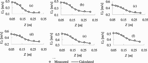
4.3 Analytical solution for depth-averaged velocity in IRCP
For a steady uniform turbulent flow, the momentum equation in the streamwise direction is combined with the continuity equation to give
It is assumed that the secondary flow contribution is linear to ρgHJ, i.e.
The eddy viscosity ϵ zx is often related to the local shear velocity u * = (τ b /ρ)1/2, depth H and the eddy viscosity coefficient λ as
This coefficient is not constant in a compound channel, with the maximum near the interface z = b mc (Xie Citation1980, Shiono and Knight Citation1991, Zhou Citation1995). It varies further in the lateral direction z, the width of the main channel b mc , or width b I of IRCP. It is described herein as
Substituting EquationEqs (14)–(17) into EquationEq. (10), and assuming U
d
2 = ηξ and ξ = α(z−b
mc
)/b
I+β for simplicity, gives a kind of Bessel equation as (Wang and Guo Citation1979)
Thus, the transverse distribution of depth-averaged velocity in the IRCP is
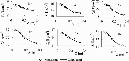
4.4 Analytical solution of depth-averaged sediment concentration in IRCP
The distribution of suspended sediment concentration was determined by considering the sediment mass balance under the influence of diffusive and convective transport. In general, for steady and uniform flow, if sediment transport is in an equilibrium state in the streamwise direction, the diffusive equation describing sediment concentration is simplified to (Chien and Wan Citation1999)
Because there is no sediment transfer across the water surface, the boundary condition requires
At the plain bed, the rate of sediment transport across the boundary is defined as the probability that a particle reaching the bed will deposit. The boundary condition for sediment transport on the bed is described as
Assuming that the sediment transport rate on the bed is linear to the depth-averaged rate, i.e. ω
b
S
b
= λ1ω
d
S
d
, and the sediment transport capacity has a similar relationship ω
b
S
bc
= λ2ω
d
S
dc
, then by combining EquationEqs (21)–(23), EquationEq. (20) is simplified as
The transverse disperse coefficient is assumed to have the same structure as the transverse eddy coefficient, namely
Substituting EquationEq. (25) into EquationEq. (24)
and assuming that ξ = α(z – b
mc
)/b
I+β, the transverse distribution of the depth-averaged sediment concentration in IRCP is
5 Conclusions
An experimental study on the flow movement and the sediment transport is presented relating to a straight and a lotus-root-shape compound channel. Using model experimentation, the main flow characteristics can be summarized as follows:
-
The flow conveying capacity is smaller in the straight compound channel than in the single channel, but larger than in the lotus-root-shape compound channel.
-
The compound cross-section can be divided into four regions in terms of flow movement and sediment transport. They comprise the (I) undisturbed region in the main channel, (II) interactive region between the channel and plain, (III) undisturbed region in the floodplain and (IV) boundary region. The width of each region was determined from measured data.
-
In both undisturbed regions (I and III), the vertical distribution of longitudinal velocity still obeys a logarithmic law, and the Rouse formula can be used for sediment concentration. There are differences in the vertical distributions of longitudinal velocity and sediment concentration between measurements and predictions in the interactive region (II), however.
-
A revised logarithmic formula is proposed using a wake function for the characteristics of the vertical velocity distribution. Based on the simplified momentum and diffusion equations, empirical expressions for the eddy and diffuse coefficients were given. Expressions to predict the transverse distributions of the depth-averaged velocity and sediment concentration are also specified. The results agree well with the measured data in the interactive region.
Notation
| B | = |
width of compound channel (m) |
| b | = |
width of main channel (m) |
| b i | = |
widths of URMC, IRCP, URFP and BR, respectively (i = I, II, III and IV) (m) |
| b m0 | = |
side width of main channel in IRCP (m) |
| b f0 | = |
side width of floodplain in IRCP (m) |
| b mc | = |
half width of main channel (m) |
| b fp | = |
half width of floodplain (m) |
| b fb | = |
width of floodplain in BR (m) |
| d 50 | = |
median diameter of sediments (m) |
| F fp | = |
Froude number in floodplain |
| F mc | = |
Froude number in main channel |
| g | = |
gravitational acceleration (m/s2) |
| H fp | = |
flow depth of floodplain (m) |
| H mc | = |
flow depth of main channel (m) |
| h d | = |
H mc −H fp (m) |
| J | = |
channel bottom slope |
| Q | = |
discharge (m3/s) |
| R fp | = |
Reynolds number in floodplain |
| R mc | = |
Reynolds number in main channel |
| S | = |
suspended sediment concentration (kg/m3) |
| S d | = |
depth-averaged sediment concentration (kg/m3) |
| S dc | = |
sediment-carrying capacity (kg/m3) |
| S fp | = |
suspended sediment concentration in floodplain (kg/m3) |
| S mc | = |
suspended sediment concentration in main channel (kg/m3) |
| S b | = |
suspended sediment concentration near bed (kg/m3) |
| S bc | = |
sediment-carrying capacity concentration near bed (kg/m3) |
| S s | = |
suspended sediment concentration near free surface (kg/m3) |
| U | = |
transect mean velocity (m/s) |
| U fp | = |
flow velocity of floodplain (m/s) |
| U mc | = |
flow velocity of main channel (m/s) |
| u | = |
flow velocity at position y (m/s) |
| u * | = |
shear velocity (m/s) |
| U, V, W | = |
temporal-mean velocities in x, z, y directions, respectively (m/s) |
| u, v, w | = |
turbulent perturbations of velocity in x, z, y directions, respectively (m/s) |
| U d | = |
depth-averaged flow velocity in IRCP (m/s) |
| x | = |
distance in streamwise direction (m) |
| y | = |
distance in normal direction from bed (m) |
| z | = |
distance in transverse direction (m) |
| α, β | = |
coefficients |
| ϵ | = |
eddy viscosity (kg/m/s) |
| φ | = |
flow depth coefficient |
| ρ | = |
water density (kg/m3) |
| μ | = |
dynamic viscosity coefficient of water (kg/m/s) |
| ν | = |
kinematic viscosity (m2/s) |
| τ | = |
bed shear stress (N/m2) |
| ρ | = |
density of water (kg/m3) |
| ω | = |
sediment settling velocity (m/s) |
Acknowledgements
This research was financially supported by the National Science Fund for Distinguished Young Scholars (50725930) and Science Fund for Creative Research Groups (50721006).
References
- Chien , N. and Wan , Z. 1999 . Mechanics of sediment transport , Reston, VA : ASCE .
- Ervine , D. A. and Baird , J. I. 1982 . Rating curves for rivers with overbank flow . Proc. Inst. Civ. Eng. , 2 ( 73 ) : 456 – 472 .
- Fukuhara , T. and Murota , A. Discharge assessment in compound channel with floodplain roughness . Intl Conf., River Flood Hydraulics . Wallingford, UK. pp. 153 – 162 .
- James , C. S. 1985 . Sediment transfer to overbank sections . J. Hydraulic Res. , 23 ( 5 ) : 435 – 452 .
- Ji , Z. W. 1997 . “ Experimental study on flow and sediment transport in compound channel ” . In Master thesis , Beijing, , China : China Institute of Water Resources and Hydropower Research . [in Chinese]
- Knight , D. W. and Shiono , K. 1990 . Turbulence measurements in a shear layer region of a compound channel . J. Hydraulic Res. , 28 ( 2 ) : 175 – 196 .
- Liu , B. Y. 1991 . “ Study on sediment transport and bed evolution in compound channels ” . In PhD dissertation , Kyoto : Kyoto University .
- Myers , W. R.C. 1978 . Momentum transfer in a compound channel . J. Hydraulic Res. , 16 ( 2 ) : 139 – 150 .
- Myers , W. R.C. and Elsawy , E. M. 1975 . Boundary shear in channel with flood-plain . J. Hydraul. Div. ASCE , 101 ( 7 ) : 993 – 946 .
- Prinos , P. and Townsend , R. D. 1984 . Comparison of methods for predicting discharge in compound open channels . Adv. Water Res. , 7 ( 2 ) : 180 – 187 .
- Rajaratnam , N. and Ahmadi , R. 1981 . Hydraulics of channels with flood-plains . J. Hydraulic Res. , 19 ( 1 ) : 43 – 60 .
- Rhodes , D. G. and Knight , D. W. 1994 . Velocity and boundary shear in a wide compound duct . J. Hydraulic Res. , 32 ( 5 ) : 743 – 764 .
- Rouse , H. 1937 . Modern conceptions of the mechanics of fluid turbulence. Paper No. 1965 . Trans. ASCE , 102 : 463 – 505 .
- Shiono , K. and Knight , D. W. 1991 . Turbulent open-channel flows with variable depth across the channel . J. Fluid Mech. , 222 : 617 – 646 .
- Tominaga , A. and Nezu , I. 1991 . Turbulent structure in compound open-channel flow . J. Hydraul. Eng. , 117 ( 1 ) : 21 – 41 .
- Tominaga , A. , Nezu , I. and Nagao , M. Hydraulic characteristics of flow in compound channels with rough floodplain . Proc. 25th IAHR Congress A, Flood and Drought . Tokyo, Japan. pp. 137 – 149 .
- Wormleaton , P. R. , Allen , J. and Hadjipanos , P. 1982 . Discharge assessment in compound channel flow . J. Hydraul. Div. ASCE , 108 ( 9 ) : 975 – 993 .
- Wormleaton , P. R. and Merrett , D. J. 1990 . An improved method of calculation for steady uniform flow in prismatic main channel/floodplain sections . J. Hydraulic Res. , 28 ( 2 ) : 157 – 174 .
- Wang , S. D. 1984 . “ Flow structure and suspend load in compound channel ” . In Master thesis , China : Wuhan University . [in Chinese]
- Wang , Z. X. and Guo , D. R. 1979 . Panorama of special function , Beijing, , China : Science Press . [in Chinese]
- Xie , H. Q. Characteristics of overbank flow and hydraulic calculation . Proc. 1st Intl. Symp. River Sedimentation . pp. 231 – 237 . Guanghua Press Beijing China . [in Chinese]
- Zhou , Y. L. 1995 . “ Experimental study of flow movement in compound channel of meandering river ” . In Master thesis , China : Wuhan University . [in Chinese]
