Abstract
Numerical simulation of high-speed turbulent water jets in air and its validation with experimental data has not been reported in the literature. It is therefore aimed to simulate the physics of these high-speed water jets and compare the results with the existing experimental works. High-speed water jets diffuse in the surrounding atmosphere by the processes of mass and momentum transfer. Air is entrained into the jet stream and the entire process contributes to jet spreading and subsequent pressure decay. Hence the physical problem is in the category of multiphase flows, for which mass and momentum transfer is to be determined to simulate the problem. Using the Eulerian multiphase and the k–ε turbulence models, plus a novel numerical model for mass and momentum transfer, the simulation was achieved. The results reasonably predict the flow physics of high-speed water jets in air.
1 Introduction
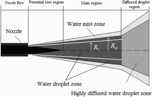
High-speed turbulent water jets having velocity of 80–200 m/s in air are extensively used in industrial cleaning operations. They exhibit a high velocity coherent core surrounded by an annular cloud of water droplets moving in an entrained air stream. Leu et al. Citation(1998) discussed the anatomy of these high-speed jets (). Much like Rajaratnam et al. (Citation1994, 1998), they divided the jet into three distinct regions:
-
Potential core regions close to the nozzle exit, instabilities cause eddies resulting in a transfer of mass and momentum between air and water with air entrainment breaking up the continuous water into droplets. There remains a wedge-shaped potential core surrounded by a mixing layer in which the velocity is equal to the nozzle exit velocity.
-
Main region where air dynamics and continuous interaction of water with surrounding air results in the break-up of the water jet stream into droplets. There is a high degree of air entrainment and the size of water droplets decreases with the increase of radial distance from the axis. Due to momentum transfer to the surrounding air, the mean velocity of the water jet decreases and the jet expands. The jet region close to the jet-axis is called the water droplet zone. Between the latter and the surrounding air, there is a water mist zone in which drops are very small and the velocity is almost negligible.
-
Diffused droplet region, where extremely small droplets of negligible velocity are produced by complete jet disintegration.
Figure 1 Anatomy of high-speed water jets in air (Leu et al. Citation1998)
Although the characteristics of submerged high-speed water jets were thoroughly studied (Long et al. Citation1991, or Wu et al. Citation1995), few experimental studies on high-speed water jets in air have been reported in the literature. Leach et al. Citation(1966) studied the pressure distribution on a target plate placed at a given axial distance from the nozzle. They demonstrated that the normalized pressure distribution along the centreline of a jet depends on the nozzle geometry while it is independent in the radial direction. The normalized pressure becomes equal to the ambient pressure at a distance of around 1.3 times the nozzle exit diameter D from the centreline. Outside this region, the shear stress is too small to clean the target surface. They also found that the normalized pressure distribution was similar for both various inlet pressure conditions and nozzle geometries.
Yanaida and Ohashi Citation(1980) did similar work and developed a mathematical expression for the centreline pressure. Unfortunately, their curve did not provide satisfactory results for the relevant axial distances in cleaning operations.
Rajaratnam et al. (Citation1994, 1998) used a converging-straight nozzle of D = 2 mm and nozzle exit (subscript “0”) velocity of around V 0 = 155 m/s. They found that the centreline jet velocity remains constant and equal to V 0 for more than 100D and then linearly decays to 0.25V 0 at about 2500D. Surprisingly, severe air entrainment causes the water (subscript “w”) volume fraction α w is the ratio of volume of a particular phase to sum of all phases present in the mixture to fall drastically. Measurements along the centreline indicate that α w at 20D is 20%, at 100D is 5% and at 200D is just 2%.
To the best of our knowledge, numerical simulation of this problem has been reported in the literature in only one instance yet the results were not validated against test results (Liu et al. Citation2004). Also their results do not simulate the actual physics as experimentally observed by Rajaratnam et al. Citation(1994). Thus the flow physics of high-speed turbulent water jets in air are simulated. The next step will be to validate the results with the available test data.
2 Novel mass-flux model
Due to Leu et al. Citation(1998), the potential core and the water droplet zones () are of prime importance for industrial cleaning, since these zones have a significant momentum to clean a surface. Yanaida and Ohashi (1980) analysed the problem by dividing the jet flow according to radial distance from the centreline (). The inner region corresponds to a continuous flow region, of which the radial width R i varies as
According to Erastov's experiment (Abramovich Citation1963), the mass flow rate of these water jets follow
Substituting EquationEq. (9) into EquationEq. (8)
gives
3 Numerical simulation
The objective is to perform numerical simulations of high-speed turbulent water jets in air and to compare the results with published test data of Rajaratnam et al. (Citation1994, 1998) and Leach et al.
Citation(1966). Equation Equation(10) needs therefore to be coupled with the continuity and momentum equations of turbulent multiphase flows.
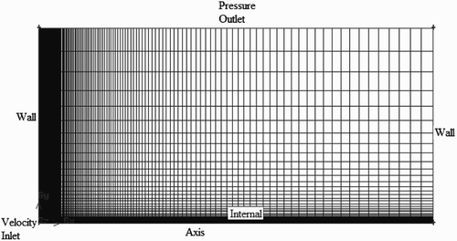
The computational domain () and a structured grid system were created in the commercial mesh generation package GAMBIT. Since this problem involves circular jets, only half of the domain was simulated in a two-dimensional axis-symmetric space. The computational space was 1000 mm × 500 mm, and a tightly clustered grid was ensured in the regions where larger flow gradients are expected. The radial extent of the domain was large enough to ensure that the pressure outlet boundary condition (set to atmospheric pressure) and the wall boundary conditions can be accurately applied, i.e. without adversely affecting the flow field. The radial width of the velocity inlet boundary (set at 155 m/s) was 1 mm as per the test conditions of Rajaratnam et al. (Citation1994, 1998).
FLUENT was applied as the flow solver. The Eulerian multiphase model and the standard k–ϵ turbulence model with standard wall functions were used to capture the flow physics. Water was treated as the secondary phase. The drag coefficient between the phases was determined by the Schiller–Naumann equation (Schiller and Naumann 1935). The continuity and momentum equations for the water phase in the Eulerian model for multiphase flows are, respectively,
The k–ϵ mixture turbulence model was used for turbulence modelling. The transport equations are:
Pressure–velocity coupling was achieved using the phase-coupled SIMPLE algorithm. All the residuals tolerances were set to 10−6 and the time step size was 10−5 s. The program was run for a time long enough to attain quasi-steady state. The default under-relaxation parameters of FLUENT were used in the computation. The discretization schemes used in the simulation are listed in .
4 Results
compare the simulation results with that of the published test data of Rajaratnam et al. (Citation1994, 1998) and Leach et al. Citation(1966). Rajaratnam et al. found that the jet centreline velocity V 0 remains constant for more than 100D and then decays linearly to about 0.25V 0 at about 2500D. Severe air entrainment causes the water volume fraction α w to fall drastically from 20% at 20D to 5% at 100D. and confirm that the simulation accurately predicts the centreline characteristics.
Figure 3 Numerical simulation of decay of centreline water-phase volume fraction and comparison with experimental results of Rajaratnam et al. (1998)
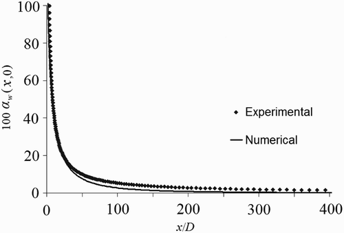
Figure 4 Numerical simulations of normalized centreline water-phase velocity and comparison with experimental results of Rajaratnam et al. (Citation1994)
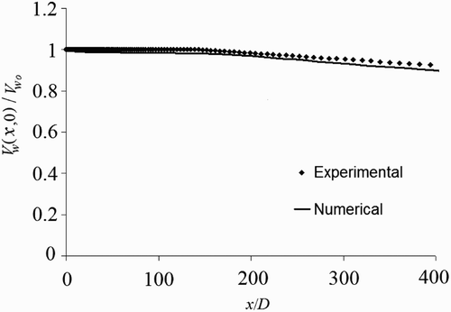
Figure 5 Velocity distribution at x/D = 100, 200, 300 and comparison with experimental results of Rajaratnam et al. (Citation1994)
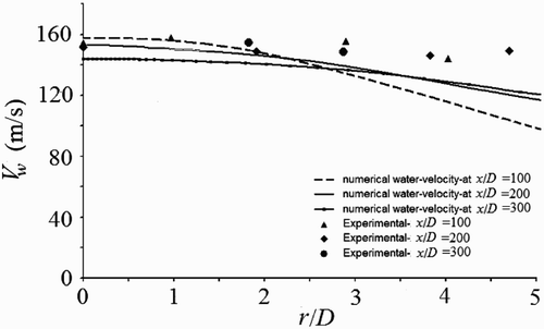
shows the velocity profiles for x/D = 100, 200 and 300. In comparison to Rajaratnam et al. Citation(1994), the velocity distribution gives good results within a radial width of 5D. Outside this region, the water mist zone is more prominent. Since the mist zone is formed of sparse droplet flows, the continuum hypothesis as a basic assumption of Eulerian model becomes invalid; hence, the model is no longer suitable to capture the flow physics.
Note that the mist zone has little effect in cleaning applications; hence its modelling is not a major concern. Thus, we can conclude that the simulation results match reasonably well with the test data of Rajaratnam et al. (Citation1994, 1998).
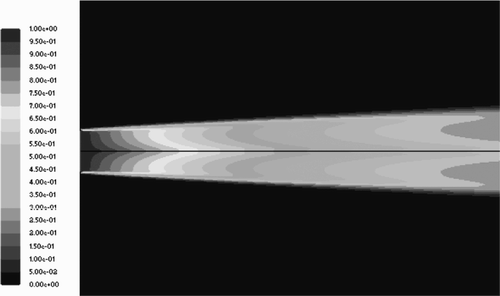
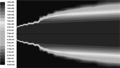
and show the velocity and volume fraction contours of the water-phase up to x/D = 10. These figures are drawn to the same geometric scale, giving a quantitative comparison between the two contours. The volume fraction contour shows that the water-phase volume fraction decays sharply with increased radial distance while the velocity contour indicates that the velocity magnitude remains almost constant for considerable radial distance. The velocity contour is much wider than the volume fraction contour. This observation is in agreement with Rajaratnam and Albers Citation(1998) yet they did not provide the results of volume fraction distribution in the radial direction. Thus, it can be concluded that a considerable amount of air is entrained within the jet. Near the outer jet region, the co-flowing air carries the water droplets (of negligible volume fraction) and has considerably high velocity. Near the centreline, the entrained air has a relatively high volume fraction increasing radially, and moving with identical velocity as the water phase.
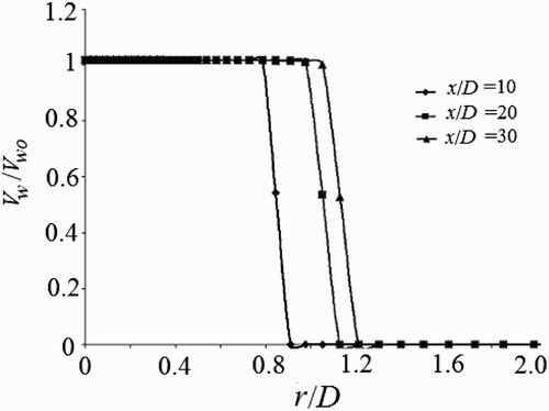
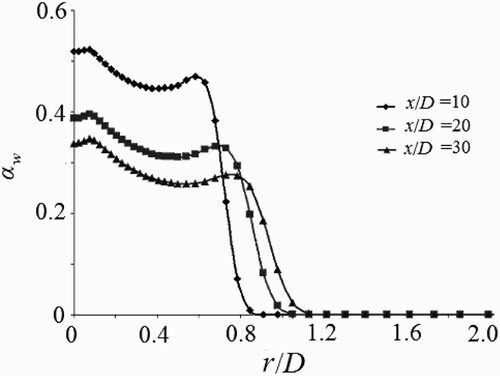
The radial distribution of the volume fraction and the water-phase velocity within x/D = 30 is of major importance in cleaning and cutting applications. and respectively show the water-phase velocity and volume fraction distributions at various axial locations. From , it is obvious that the potential core still exists at x/D = 30. shows that the volume fraction of water drops from 0.43 at x/D = 10 to 0.21 at x/D = 30, indicating the amount of air entrainment along the centreline. The distribution of water-phase volume fraction is expected to be Gaussian (Rajaratnam and Albers Citation1998), but the simulation results show a distribution close to Gaussian with a bulge at the jet–air interface. Since it is impossible to predict the mist region with an Eulerian approach, the volume fraction of water actually lost as mist numerically accumulates near the jet–air interface and produces the erroneous bulging effect. The bulging effect flattens out with increased axial distance. The entrained air flows with the same velocity as the water-phase, but owing to low air density in comparison to water (∼1:815); the momentum delivered to cutting or cleaning surface is significantly reduced.
From an application point of view, the pressure distribution on a target (subscript “T”) plate P T placed perpendicularly to the jet flow field is of prime concern. Since the jet loses a sufficient amount of centreline pressure P T(x,0) as it travels, the target plate should be kept near the nozzle exit to ensure efficient cutting or cleaning. It is essential for the simulation to predict the pressure distribution at the target plate accurately, hence the test conditions with a jet velocity of 350 m/s and nozzle radius of 0.5 mm of Leach et al. Citation(1966) were numerically implemented. compares the simulation results with the experiment.
Figure 10 Normalized pressure distribution on a target plate placed at 76D and comparison with Leach et al. (Citation1966)
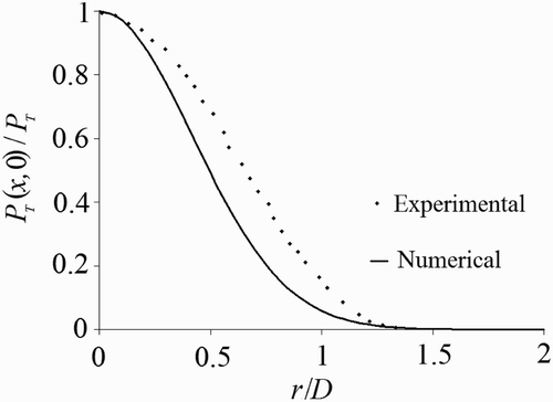
The numerical simulation matches well near the centreline but deviates slightly toward the edge. Leach et al. Citation(1966) used a third-order polynomial curve fit for their test data to represent the radial pressure distribution. According to Guha Citation(2008), the test results for different nozzle exit velocities indicate that the Gaussian fit is more appropriate (). Since the present simulation results resemble the Gaussian distribution, the flow physics are more accurately predicted than by the experiments.
Figure 11 Experimental normalized target pressure along radial direction and comparison with Leach et al. Citation(1966) (from Guha Citation2008)
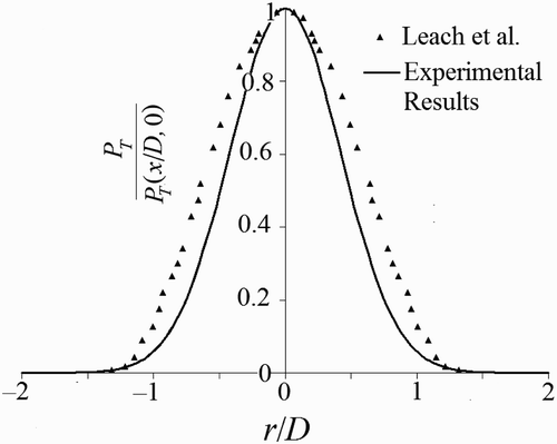
Table 1 Discretization schemes for jet flow
5 Conclusions
Numerical simulations were performed to capture the entrainment of surrounding air into high-speed water jets. The simulation reasonably predicts velocity, pressure and volume fraction distributions of high-speed water jets in air. The results accurately describe the centreline characteristics, but under-predict the velocity and over-predict the volume fraction distribution near the jet edge. Since the near-edge region is predominantly a sparse droplet flow region, the Eulerian models fail to accurately capture the physics. The proposed simulation methodology is helpful for predicting the flow behaviour of jets used in industrial cleaning applications since these focus on the near-field jet region.
Notation
| D | = |
diameter of nozzle |
| F | = |
momentum source term |
| G | = |
production of turbulent kinetic energy |
| k 1, C | = |
spread coefficients |
|
| = |
axial mass flux of water droplets |
|
| = |
mass transfer |
| P | = |
pressure |
| r | = |
radial distance |
| R | = |
radial width of jet droplet zone |
| S | = |
mass source term |
| x | = |
axial distance |
Greek symbols
| ϵ | = |
turbulent dissipation rate |
| μ | = |
viscosity |
| ρ | = |
density |
Subscripts
| a | = |
air |
| i | = |
inner |
| m | = |
mixture |
| o | = |
outer |
| t | = |
turbulent |
| w | = |
water |
| 0 | = |
nozzle outlet |
Additional information
Notes on contributors
Anirban Guha
Department of Civil Engineering, University of British Columbia, Vancouver, BC, Canada V6T1Z4References
- Abramovich , G. N. 1963 . The theory of turbulent jets , Cambridge, MA : MIT Press .
- FLUENT 6.3.26 User manual
- Guha , A. 2008 . “ Modeling of high-speed water jets in air ” . In MSc thesis , Ontario, , Canada : Mechanical, Automotive and Materials Engineering Dept. University of Windsor .
- Leach , S. J. , Walker , G. L. , Smith , A. V. , Farmer , I. W. and Taylor , G. 1966 . Some aspects of rock cutting by high-speed water jets . Phil. Trans. R. Soc. Lond. A , 260 ( 1110 ) : 295 – 310 .
- Leu , M. C. , Meng , P. , Geskin , E. S. and Tismeneskiy , L. 1998 . Mathematical modeling and experimental verification of stationary water jet cleaning process . J. Manuf. Sci. Eng , 120 ( 3 ) : 571 – 579 .
- Liu , H. , Wang , J. , Kelson , N. and Brown , R. J. 2004 . A study of abrasive waterjet characteristics by CFD simulation . J. Mater. Process. Technol , 153–154 ( 1–3 ) : 488 – 493 .
- Long , D. , Steffler , P. M. , Rajaratnam , N. and Smy , P. 1991 . Structure of flow in hydraulic jumps . J. Hydraulic Res. , 29 ( 3 ) : 293 – 308 .
- Rajaratnam , N. and Albers , C. 1998 . Water distribution in very high velocity water jets in air . J. Hydraul. Eng. , 124 ( 6 ) : 647 – 650 .
- Rajaratnam , N. , Steffler , P. M. , Rizvi , S. A.H. and Smy , P. R. 1994 . Experimental study of very high velocity circular water jets in air . J. Hydraulic Res. , 32 ( 3 ) : 461 – 470 .
- Schiller , L. and Naumann , A. 1935 . Über die grundlegenden Berechnungen bei der Schwerkraftaufbereitung . Z. Ver. Deutsch. Ing. , 77 ( 33 ) : 318 – 320 . [in German]
- Wu , S. and Rajaratnam , N. 1995 . Free jumps, submerged jumps and wall jets . J. Hydraulic Res. , 33 ( 2 ) : 197 – 212 .
- Yanaida, K., Ohashi, A. (1980). Flow characteristics of water jets in air. 5th Intl. Symp. Jet cutting technology, BHRA Fluids Engng. A(3), Hannover, Germany, 33–44.
