Abstract
A parallel study of regression and semi-theoretical equations is presented to forecast the drop force and the drop length of a free-falling nappe for an aerated straight-drop spillway. The ratio between the critical velocity and the exit velocity at the drop wall was introduced to establish semi-theoretical equations. Regression techniques were applied by using the dimensionless channel bed slope and the drop number to describe the drop characteristics. There were 64 groups of test data to calibrate the parameters of equations. Another 36 groups of test data were used to verify the developed model. The simulation results indicate that the semi-theoretical method provides reliable estimates for the drop force, and that the regression method can offer accurate predictions for the drop length.
1 Introduction
Check dams, drops, stepped spillways and cascades are common in stormwater systems, dam outlets and water treatment plants (Chanson and Toombes Citation1998). These structures may generate a free-falling nappe associated often with a scour hole (Chanson Citation1995, Citation1996, Chanson and Toombes Citation1998, Mossa et al. Citation2003, Chanson and Gualtieri Citation2008), yet the drop force is rarely discussed. The aim of this study is therefore to predict the drop force and the drop length of free-falling jets by semi-theoretical equations and regression techniques. A series of test data was used to calibrate the proposed equations, and further test data were used to verify these formulae.
2 Experimental apparatus and methods
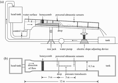
The tests were conducted in a 12 m long, 0.3 m wide and 0.4 m deep channel, whose sidewalls were made of glass panels. The bottom slope was adjustable (). The discharge was accurately controlled by a constant head tank with a variable-speed electronic controller.
The bottom slope upstream of the drop in a river is usually small because of silt accumulation, such that it was adopted to zero herein. Beyond the drop, a free-falling jet develops with an air cavity beneath the nappe (Chanson and Toombes Citation1998). The air cavity was ventilated by holes in the drop wall (). The flow depths in the drop vicinity and the bed pressures of the pool zone were measured by RPS-401® powered ultrasonic sensors and eight KYOWA® pressure transducers, respectively. The drop characteristics were investigated by varying the bottom slope S o of the pool zone from 0 to 9%, the drop height H from 0.15 to 0.30 m and the unit discharge q from 0.0076 to 0.0402 m2/s (). Note that the Froude number is F = v/(gh)1/2, where v is the water velocity and h the flow depth; the Reynolds number is R = vR h /ν, where R h is the hydraulic radius and ν the kinematic viscosity of water. Subscripts o and w relate to approach flow and tailwater conditions, respectively.
Table 1 Experimental flow conditions
displays the test conditions. There were 64 groups of test data of Huang and Chen Citation(2008) to calibrate the model. The authors conducted 36 groups of new test data to simulate the results. Most of approach flows to the drop were trans- and supercritical flows.
The drop number D = q 2/(gH 3) was excessively studied in the past, in which g is the gravitational acceleration and H the drop height. Rand Citation(1955) found that the flow geometry of straight-drop spillways can be described by only D. Chinnarasri and Wongwises Citation(2004) discovered that as D increases, the energy loss ratio decreases. The Federal Highway Administration (Citation2006) classified the “low drop” structure if D > 1. indicates that the present D values result in a “high drop”.
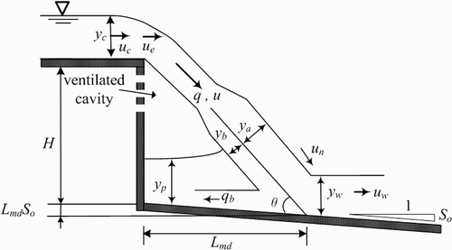
shows a free-falling nappe of an aerated straight-drop spillway, where u e is the exit drop velocity. The distance measured (subscript m) from the drop to the maximum pressure position was defined as the drop length L md (). The vertical unit drop force F md was determined by the measured drop pressure P of the downstream channel as follows:
3 Analysis of drop characteristics
3.1 Semi-theoretical equations
For critical (subscript c) flow,
also shows the drop area, onto which the nappe impacts the channel generating flow recirculation and thus increasing the discharge q b into the nappe, changing the nappe velocity near the channel. According to momentum conservation in the vertical direction, the semi-theoretical vertical unit drop force F td is given as follows:
3.2 Regression equations
From EquationEq. (7), the regression (subscript r) drop length L
rd
is given by
4 Discussion of drop characteristics
4.1 Accuracy of drop characteristics
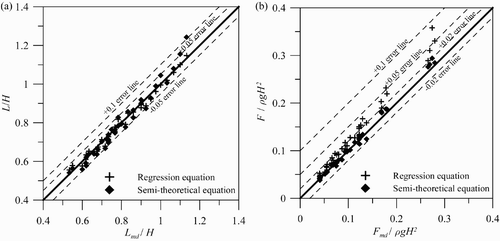
compares the semi-theoretical and regression equations using dimensionless parameters. The root-mean-square error (RMSE) was also determined to estimate the difference between measured and predicted values.
Figure 3 Comparison between measured/predicted drop characteristics: (a) dimensionless drop length and (b) vertical unit drop force

4.1.1 Drop length prediction
Except for two values, the predictions using the semi-theoretical equation are within ±0.05. The RMSE (= 0.0328) of the semi-theoretical method is larger than that of the regression method (= 0.0194). Therefore, the regression approach can be applied to predict the drop length.
4.1.2 Unit drop force prediction
The semi-theoretical equation can be used to predict the unit drop force to be within ±0.02, except for two values within the range of 0.05. The RMSE of the semi-theoretical method (= 0.0069) is smaller than that of the regression method (= 0.0270). Therefore, semi-theoretical method provides a better estimate.
Scale effects may exist if dimensionless terms have different values between model and prototype (Chanson and Gualtieri Citation2008). Henderson Citation(1966) stated that the drag coefficients of the model and prototype are identical for Reynolds number R > 1000. Herein, R > 10,000 as shown in . The dimensional analysis indicates that the drop characteristics are D, F and S o . Therefore, the present method can be used to simulate free-falling jets of high drops (0.00026 ≤ D ≤ 0.04874), mild tailwater slopes (0% ≤ S o ≤ 9%) and transcritical approach flow (0.83 ≤ D ≤ 1.48).
4.2. Drop length comparison with literature
Rand Citation(1955) (subscript r) estimated the drop length L rd by the regression method for aerated nappes as follows:
Chanson Citation(1995) assumed that the flow upstream of the drop is subcritical, and suggested for non-aerated nappes
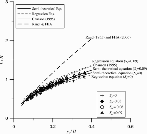
shows the relationship between the dimensionless drop length and the dimensionless critical depth. Rand Citation(1955) and Federal Highway Administration (2006) obviously overestimated the drop length. Although the equation of Chanson Citation(1995) overestimates the drop length, his trend is closer to the present test data than the others. The discrepancy between Chanson's and the present data may be attributed to the downstream slope, resulting in a longer drop length.
5 Conclusions
The drop characteristics of a free-falling nappe were determined by regression techniques and a semi-theoretical approach. The semi-theoretical method provides an accurate estimation for the unit drop force, and the regression method accurately predicts the drop length. This study includes the effect of tailwater channel slope on the drop length. The results apply to relatively high drops, mild tailwater slopes and transcritical approach flow. Further research is required to generalize the present experimental limitations.
Notation
| D | = |
drop number (-) |
| F md | = |
vertical unit drop force (N/m) |
| F | = |
Froude number (-) |
| H | = |
drop height (m) |
| L d | = |
drop length (m) |
| P | = |
drop pressure (N/m2) |
| q | = |
unit discharge (m2/s) |
| R | = |
Reynolds number (-) |
| S o | = |
bottom slope (-) |
| u | = |
velocity (m/s) |
| y c | = |
critical flow depth (m) |
| α | = |
velocity ratio (-) |
Subscripts
| a | = |
effective |
| b | = |
below |
| c | = |
critical |
| d | = |
drop |
| e | = |
exit |
| m | = |
measured |
| n | = |
nappe |
| o | = |
approach flow |
| r | = |
regression |
| t | = |
semi-theoretical |
| w | = |
tailwater |
References
- Chanson , H. 1995 . Hydraulic design of stepped cascades, channels, weirs and spillways , Oxford, , UK : Pergamon .
- Chanson , H. 1996 . Discussion to energy loss at drops . J. Hydraulic Res. , 34 ( 2 ) : 273 – 278 .
- Chanson , H. and Gualtieri , C. 2008 . Similitude and scale effects of air entrainment in hydraulic jumps . J. Hydraulic Res. , 46 ( 1 ) : 35 – 44 .
- Chanson , H. and Toombes , L. 1998 . Supercritical flow at an abrupt drop: Flow patterns and aeration . Can. J. Civ. Eng. , 25 ( 5 ) : 956 – 966 .
- Chinnarasri , C. and Wongwises , S. 2004 . Flow regimes and energy loss on chutes with upward inclined steps . Can. J. Civ. Eng. , 31 ( 5 ) : 870 – 879 .
- Federal Highway Administration . 2006 . “ Hydraulic design of energy dissipators for culverts and channels ” . In Hydraulic Engineering Circular , Denver, CO : U.S. Department of Transportation . No. 14, 11-2, ed. 3
- Ferro , V. 1992 . Flow measurement with rectangular free overfall . J. Irrigation Drainage Eng. , 118 ( 6 ) : 956 – 964 .
- Henderson , F. M. 1966 . Open channel flow , New York, , USA : MacMillan .
- Huang, H.S., Chen, J.D. (2008). Study of impact force by free overfall flow. Proc. 17th Hydraulic Engng. Conf. Chinese Institute of Civil and Hydraulic Engineering, Taichung Taiwan, [in Chinese], C(25), 1–8.
- Mossa , M. , Petrillo , A. and Chanson , H. 2003 . Tailwater level effects on flow conditions at an abrupt drop . J. Hydraulic Res. , 41 ( 1 ) : 39 – 51 .
- Rand , W. 1955 . Flow geometry at straight drop spillways . J. Hydraul. Div. ASCE. , 81 ( 791 ) : 1 – 13 .
- White , M. P. 1943 . Discussion on energy loss at the base of a free over-fall . Trans. ASCE. , 108 : 1361 – 1364 .


