Abstract
Solution monitoring (SM) is a type of process monitoring (PM) intended to improve nuclear safeguards in large commercial facilities that contain solutions. Typically, masses (M) and volumes (V) are estimated from frequent in-process measurements. Transfers between tanks can be identified in these data, segments of which can then be compared to generate transfer differences (TDs). A safeguards concern might then be raised if either these TDs or deviations in M or V data during “wait” modes become significant. Average M and V TDs should be 0 (perhaps following a bias adjustment) to within a historical limit that is a multiple of the standard deviation of the M or V TD, as should deviations during “wait” modes. Statistical test options can be compared on the basis of their estimated probabilities to detect various material loss scenarios. Multivariate statistical PM options have previously been applied to residuals produced from simulated SM data that had no process variation, only random and systematic measurement errors. This article examines how detection probabilities might be estimated with real data. To do this, realistic effects such as pump carryover, evaporation, condensation, and mixing/sparging, are included in simulated data. In real facilities false alarms are a concern, particularly when data need to be evaluated regularly, on a day-to-day basis. The need to widen control limits to avoid alarming on innocent process variation effects is discussed, and the consequential reduction in DPs is illustrated with numerical examples.
1. Introduction
Solution monitoring (SM) is a type of process monitoring (PM) intended to improve nuclear safeguards in facilities such as reprocessing plants [Citation1–Citation14]. In a modern large reprocessing facility, such as the Rokkasho Reprocessing Plant (RRP), SM is used to provide assurance that the facility is operating as declared. The main roles for SM as an additional measure in international safeguards are to provide direct or indirect support of inventory measurement for near-real-time accounting (NRTA) and to provide a tool for data consistency monitoring [Citation3,Citation7,Citation8]. To attain the timeliness goal, interim inventory verification (IIV) has to be performed with NRTA at the RRP. Because of the large RRP throughput, frequent inventory verification with minimum intrusion to facility operation is desired. Alternatively, a combination of real-time PM and less frequent IIV with NRTA has been proposed. In this role, a further possibility for SM data in international safeguards has been demonstrated by estimating the operator's loss detection probabilities for various cases. In the present safeguards approach, SM is not fully utilized despite the huge amount of automatically generated SM data. Although quantitative metrics to evaluate SM data are still developing, SM is a candidate supplement to NRTA in future bulk handling facilities.
Typically in SM, masses (M) and volumes (V) are measured from frequent in-process measurements. Transfers between tanks can be identified in these data, so that transfer differences (TDs) can be generated. A safeguards concern might then be raised if either these TDs or deviations in M or V data during “wait” modes become significant. Currently the term “significant” is interpreted in a subjective manner [Citation6,Citation10]. A statistical approach would provide more rigor. To do this, statistical significance would probably be based on assuming that the average residual will be zero (perhaps following a bias adjustment) to within a historical limit that is a multiple of the standard deviation of the residual. The residual is either the M or V TD or the M or V change during “wait” mode. To investigate this possibility, a few multivariate statistical PM options have previously been applied to these residuals using “vanilla” simulated SM data that had no process variation, only random and systematic measurement errors [Citation2,Citation4,Citation5,Citation6,Citation11,Citation12]. The main performance measure has been the estimated loss detection probability (DP) for various material loss scenarios.
This article goes further by examining what happens when realistic effects observed in real SM data are included in simulated data, such as pump and pipe carryover (temporary changes in solution in the unmonitored transfer lines between tanks), evaporation, condensation, and mixing/sparging. Consideration is also given to the practical challenge that involves the need for SM to be part of the day-to-day assessment without leading to too many “alerts” or “alarms,” so we widen the control limits to avoid alarming on innocent process variation effects. Widening the control limits lowers the DPs as illustrated with numerical examples.
The main findings are:
| 1. | Process variation results in more complicated statistical distributions and reduces loss detection probabilities compared to the case of zero process variation. M and V changes in some tanks during “wait” or “transfer” modes cannot be adequately described by common probability distributions such as the normal distribution. Because of “process variation,” a mixture of distributions having different mean values (some positive, others negative, others near zero) is required. These nonzero means are caused by evaporation, condensation, other heating and cooling effects, and temporary deposits and withdrawals from the solution transfer lines (airlift at some plants, pumps at others). Process variation effects should be evaluated using statistical methods; the main statistical distribution to be used here is a mixture of components that have different mean values. | ||||
| 2. | Continuous modes in tanks reduce loss detection probabilities. Tanks that have a continuous ship or receive mode have considerably lower loss DP than batch receipt and batch ship mode tanks. | ||||
| 3. | There are relatively sample size requirements for training SM algorithms. Approximately 100 or more wait or transfer modes for each tank or pair of tanks are required to adequately estimate the specific statistical distribution for that tank, and corresponding loss DPs in future tank data. | ||||
| 4. | The usual Gaussian distribution can perhaps still provide an adequate approximation. Although not strictly correct, the normal (Gaussian) distribution might still provide a reasonably accurate (sometimes biased high, sometimes biased low) approximation to the actual mixture distribution described in finding (1). This is because the estimated variance is inflated by the presence of ignored multiple means, and DPs estimated from a variance-inflated normal distribution are reasonably accurate. Therefore, it might be adequate to continue to assume a bivariate normal distribution for (M,V) pairs that are monitored during each tank's wait and transfer modes. One concern here is the possible need for very low per-event and per-tank false alarm rates which requires accurate probability estimation in the tails of the actual distribution. The other concern is that this rough approximation will be biased low in some cases and high in other cases, so unless each tank and tank pair were actually evaluated in training data, it would not be possible to assess the quality of the rough approximation. | ||||
The following sections include background of SM evaluation, description of simulated data from Glasgow University's (GU) Reprocessing Plant Simulation Program (GU-RPSP), examples from real facility SM systems, effects observed in real SM data, loss DP estimation, and the impact of having some tanks with a continuous ship or receive mode compared to batch mode.
2. Background of SM evaluation
Traditional SM data available essentially continuously in each tank are three hydrostatic pressures and a temperature (T). These are combined to give solution level (L), density (D), and temperature (T), where L and D are based on common measurements and hence have correlated errors. In addition, L and D measurements can vary when tank contents are not in a settled, static state. Such variability is therefore one example of “process variation.” Calibrations relating volume (V) to L as a function of T are available, so solution V and mass M (M = V × D) are also available essentially continuously [Citation14–Citation16]. Measurement errors associated with M and V are therefore also likely to be correlated and possible somewhat complicated. Various filters are applied, reducing the data to an (L,D,T,V,M) vector approximately every 5 min from each tank [Citation17,Citation18]. Some SM evaluation systems (SMES) mark this 5-min data to find regions of interest such as transfers and other transients such as mixing or sparging or sampling [Citation7,Citation10].
Currently, there are two main types of SM evaluation methods: (1) monitor each tank cycle for approximate agreement with its “reference signature” or typical behavior during each cycle [Citation14], and (2) monitor the M and V transfer difference in each tank-to-tank transfer and during all “wait” modes for each tank [Citation2,Citation3,Citation7,Citation8,Citation10]. Both evaluation types result in “residuals” that arise by comparing observations to predictions. In finding (1), the prediction in a given tank cycle is the “reference signature” for that tank. In finding (2), the predictions are based on assuming that the average M and V TD will be zero (perhaps following a bias adjustment) to within a historical limit that is a multiple of the standard deviation of the M or V TD. A few multivariate statistical process monitoring (PM) options have been applied to finding (2), and other options could also be applied to finding (1). This article will only discuss type (2) monitoring.
One study [Citation6] evaluated SM benefits on the basis of estimated misuse DPs that might be achieved by several statistical PM options in type (2) monitoring of M and V TDs and M and V changes during tank wait modes. DP estimates were based on Python-simulated M and V data provided by GU-RPSP code [Citation9]. Python is a powerful but relatively simple object-oriented programming language that easily ports across windows, unix, and mac platforms (www.python.org)
The GU-RPSP tracks U, Pu, HNO3, H2O, and lumps all other constituents into a category denoted as ‘X.’ Discrete time steps are used to update constituent masses in each tank using flow rates as specified by the user in input files that initialize tank classes. However, in [Citation6] the assumed measurement error effects were simplistic, optimistic, and process variation effects were ignored. Measurement error effects in real SM data suggest that the standard deviation of the M and V TD in tank-to-tank transfers is approximately 5–10 times larger than international target values [Citation19] and tank calibration studies suggest [Citation5,Citation15,Citation16]. SM systems of type (1) or (2) will have lower loss DPs as a result of process variation effects such as varying evaporation rates, varying amounts of solution carryover, and temperature changes that impact volume measurements. More realistic simulated SM data are reanalyzed here using multivariate statistical PM options to estimate loss DPs for various loss scenarios. Because not all tanks have independent inspector measurements, these DPs should be viewed as operator rather than inspector loss DPs because the possibility of data falsification by the operator to conceal facility misuse from the inspector is not being considered here [Citation20].
3. Adding realism to simulated data
is a plot of tank volume versus time step for four tanks simulated in GU-RPSP. In , each time step is 5 min, so the time span is approximately two days. The data have zero measurement error and zero process variation. A given tank has identical behavior in each tank cycle. Tank volumes are simulated on the basis of flow rates into and out of each tank as specified by the user in input files that define tank classes [Citation9]. By editing the input files, the user can modify the flows so that tank cycles are not all identical.
Figure 1. Volume time series in tanks from GU-RPSP without measurement error or process variation: (a) input accountability tank (Stage 1 IAT); (b) buffer tank 1 (Stage 1 Buffer 1); (c) buffer tank 2 (Stage 1 Buffer 2); (d) control tank (Stage 1 control).
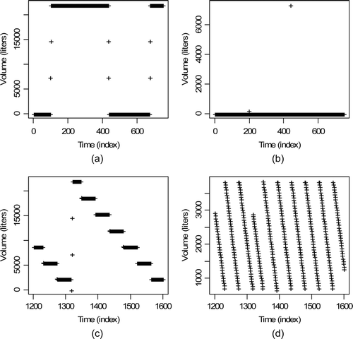
We modified the V and D data for the four tanks in by including independent random measurement errors, systematic measurement errors, and process variations due to pump and/or pipe carryover during shipments and receipts and process variation due to evaporation and/or condensation during wait modes.
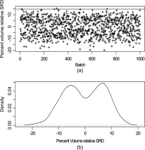
A reasonable model for carryover [Citation7,Citation21] is a mixture of possible temporary gains or losses during the transfer. plots 1000 simulated realizations of the V shipment from the input accountability tank (IAT) at time index approximately 400 and the corresponding receipt in the stage 1 buffer tank 1. The mixture behavior is clearly evident in b, illustrating a bi-modal distribution.
Figure 2. (a) Percent volume relative TD from tank 1 (IAT) to tank 2 (buffer) for each of 1000 batches. The upper line near 14% is at twice the simulated-based approximation estimates RSD of 7%. (b) Estimated probability density of the percent volume relative TD.
For , simulated shipment measurements were generated using
There are two process variation terms in Equation (1). The process variation term PV 1 is also assumed to be normal with relative standard deviation σ PV1 = 0.02, depicting random effects observed in real data that are too large to be explained by measurement error alone. The process variation term PV 2 is a mixture with equal (1/3) probability from three random signed values whose magnitudes are normal with relative standard deviation σ PV1 = 0.01 (see Section 4). The signed values represent give-and-take quantities due to the solution transfer mechanism. A plus sign indicates a “give” to the pipes/pump and a minus sign indicates a “take” from the pipes/pump. The sign was randomly generated for each event, with a probability 0.5 for plus and 0.5 for minus to model random pattern in the sequence of “giving” and “taking” from the pipes/pump. This PV 2 is therefore a mixture of three mean values, with each value representing an average M or V amount given to or taken from the pipes/pump during each tank-to-tank transfer. If one averaged over many TDs then the central limit effect implies that the average TD should be approximately Gaussian in distribution. However, individual TDs will exhibit the mixture behavior and because the SM system must also evaluate individual TDs, the mixture model is needed. Choosing the number of mixture component requires training on real data; here, the choice of three mixture components gives reasonable agreement with available training data.
The e marking error term would be zero if the start and stop time of the shipment and receipt were identified perfectly without marking error [Citation7]. However, there will be marking errors, so e marking contributes to the TD measurement error. There can be both random and systematic (such as usually being late with the mark of the start of an event) effects in e marking. Simulation is valuable in assessing the impact of marking error. Because real data are often recorded every 1 min, we linearly interpolated the 5-min data output from GU-RPSP to 1-min data, and marked the 1-min data with estimated start and stop times of events using custom marking algorithms in R [Citation22]. All error modeling and DP-related simulations were performed in R.
As a rough approximation, ignoring marking error, the relative standard deviation of the amount shipped is
is the same as , but is for the volume TD between the bottom two tanks in (Buffer and control tanks). Again the horizontal alarm limit line in a is at twice the estimated RSD, with an simulation-based estimated RSD of 0.11, which is considerably larger than 0.03. Event marking is more error prone in the shipments from the buffer to control tanks because the control tank ships continuously and because there is an additional relative standard deviation of 0.01 in the flow rate (1% relative) during each shipment from the control tank. Note that the control tanks ships constantly, including during the receipt from the Buffer tank. The same rough approximation ignoring marking error
Figure 3. Same as Figure 2, but for tank 3 (buffer) to tank 4 (control) shipments.
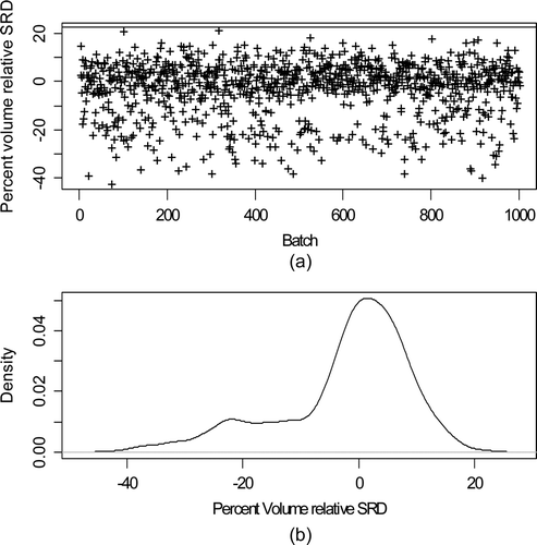
In summary, the simulation-based estimates of the %RSD of the TDs are 7% for the B/B (batch receipt/batch ship) mode shipment from the IAT to the buffer and 11% for the B/C (batch receipt/continuous ship) mode shipment from the buffer tank to the control tank. These estimates are for illustration only, but it has been noted that as in this simulated data, the V and M TDs are larger in real data than calibration data for individual tanks would predict. Burr et al. [Citation5] report RSDs in real data of approximately 10%, in good agreement with these simulated RSDs.
The corresponding estimated relative V changes during wait modes for tank 1 (IAT) and tank 3 (buffer tank) are approximately 2%, again in reasonable agreement with those found in real L data. In wait modes, most errors essentially cancel because the initial and final true L are nearly identical. The 2% relative V changes are due nearly entirely to random measurement error and process variation due to varying evaporation and/or condensation rates.
4. Mixture distributions
It is common to set alarm thresholds assuming the M and V TDs have approximately a normal distribution. Therefore, a key question in the SM context is the extent to which percentiles of the real distribution agree with those of a corresponding normal distribution. Any real distribution can be well approximated by a mixture of normal densities, which we use here, as in and . Therefore, in the next subsection we examine the extent to which percentiles of a mixture of normals agree with percentiles of a corresponding variance-inflated single-component standard normal.
For example, in the IAT to buffer tank transfers (scaled to unit variance), the 90, 95, 99, and 99.9% percentiles are 1.33, 1.55, 1.92, and 2.22, respectively. In the corresponding standard normal distribution having the same mean (0) and variance (1) as the mixture distribution (a RSD of 7% or 11% for tank 1 to tank 2 or tank 3 to tank 4, respectively, but then scaled to unit variance), the 90, 95, 99, and 99.9% percentiles are 1.33, 1.69, 2.48, and 3.20, respectively. Therefore, the corresponding normal distribution has a higher probability of exceeding large values such as 2.48 (in scaled units) than the approximating mixture distribution. The simulated mixture distribution has probabilities of 0.1, 0.03, 0.001, and <0.0001 of exceeding 1.33, 1.69, 2.48, and 3.20, respectively. Therefore actual false alarm probabilities are smaller than those from the corresponding standard normal distribution. At first glance, this result is encouraging because it suggests that using a simple normal.
Approximation (not a mixture) will give conservative results, resulting in lower false alarm rates than nominal. However, in the tank 3 to tank 4 V TDs, the 90, 95, 99, and 99.9% percentiles are 1.69, 2.03, 2.73, and 2.98, respectively. In this case, the opposite effect occurs, with the single-component standard normal having slightly lower probability of exceeding moderately large values such as 2.73. Or, stated another way, if one assumes the standard Gaussian percentiles are adequate for the mixture distribution, the actual tail probabilities from the simulated mixture distribution are 0.09, 0.04, 0.01, and 0.002 rather than the nominal 0.1, 0.05, 0.01, and 0.001.
We also analyzed wait modes for the tank 1 (IAT) and tank 3 (buffer tank). In the tank 1 relative V changes, the 90, 95, 99, and 99.9% percentiles are 1.39, 1.89, 3.06, and 3.72, respectively. And for the single-component standard normal, the 90, 95, 99, and 99.9% percentiles are still 1.33, 1.69, 2.48, and 3.20, respectively. The corresponding observed tail probabilities in the simulated mixture are 0.11, 0.08, 0.03, and 0.004, respectively. In the tank 3 relative V changes, the 90, 95, 99, and 99.9% percentiles are 1.42, 1.81, 2.71, and 4.24, respectively. And for the single-component standard normal, the 90, 95, 99, and 99.9% percentiles are 1.29, 1.63, 2.24, and 3.00, respectively. The corresponding observed tail probabilities in the simulated mixture are 0.12, 0.07, 0.02, and 0.005, respectively. Note that the normalized percentiles of the tank 1 and tank 3 wait modes are larger than the percentiles of the corresponding single-component standard normal distribution. So, assuming a single-component standard normal approximating distribution leads to actual tail probabilities being larger than the nominal tail probabilities.
We next investigate further the behavior of mixtures of normal (Gaussian) variables.
4.1. Mixtures of scalar-valued Gaussian variables
A mixture [Citation23] X arising from mixing N component (Ncomp) scalar-valued Gaussian random variables can be expressed as , where π
i
is the probability that component i is chosen, and component i is Gaussian with mean μ
i
and standard deviation σ
i
, denoted as
. In the SM context, μ1 > 0 for a particular batch transfer when solution from the receiver tank is partly donated to the pipe work and μ2 < 0 when solution is drained from the pipe work to the receiver tank in a different batch transfer.
It is sufficient here to consider the case where the means μ
i
differ among components, but the standard deviations σ
i
are the same in each component, denoted σ. The mean and standard deviation of the mixture are then and
. Our main interest is in the probabilities of exceeding specified thresholds. It can be shown by straightforward calculation that
Perhaps surprisingly, for many mixtures, these probabilities are smaller than those of the corresponding reference distribution, which is a single-component Gaussian having the same standard deviation as the mixture, σmix. Therefore, higher probabilities of mean-centered values exceeding kσ are not necessarily expected. However, for many other mixtures, particularly those having very unequal π i , the tails are fatter (giving larger probabilities to extreme values) than the reference Gaussian. For example, if the random variable X arises a mixture consisting of three components having π1 = 0.083, π1 = 0.83, and π3 = 0.083 and μ1 = −3, μ2 = 0, and μ3 = 5 with σ = 1, then P(|X − μmix| > kσmix) = 0.079, 0.022, and 0.0006 for k = 2, 3, and 4, respectively, and the kurtosis equals 2.76. The kurtosis is the ratio of fourth moment to the fourth power of the standard deviation minus 3 (E(X 4)/{E(X)}4 − 3, where E denotes expected value with respect to the distribution of X) and the kurtosis of a standard normal distribution is 0. The corresponding probabilities for the single-component reference Gaussian are 0.046, 0.003, and 0.00006, which are significantly smaller, indicating that this particular mixture has fatter-than-Gaussian tails. On the other hand, if the random variable X arises a symmetric mixture consisting of three components having π1 = 0.25, π1 = 0.5, and π3 = 0.25 and μ1 = − 3, μ2 = 0, and μ3 = 3 with σ = 1, then P(|X − μ mix| > kσ mix) = 0.023, 0.000014, and 4.4 × 10⁻¹¹ for k = 2, 3, and 4, respectively, indicating that this mixture has thinner-than-Gaussian tails. And, its kurtosis equals −0.67.
Although kurtosis measures tail behavior fairly well, it is possible for a distribution to have less than Gaussian kurtosis, yet have higher probability of exceeding some of these thresholds, and vice versa. For example, one example 10-component Gaussian having very different component fractions has kurtosis −0.333 but P(|X − μmix| > kσmix) = 0.0002. This is significantly larger than the corresponding probability for a single-component Gaussian, which is 0.00006.
Skewness and kurtosis are two of many measures used to gauge how close a distribution is to Gaussian [Citation23,Citation24]. Testing for univariate or multivariate normality is somewhat of an art because: (1) there are many possible tests; (2) any test applied to real data is practically guaranteed to reject the Gaussian hypothesis provided the sample size is large enough, and (3) some types of non-normal behavior can be present, yet the Gaussian approximation is still adequate for some goals. Regarding (2), the probability of detecting nonGaussian behavior approaches one as the sample size increases, even if the departure from normality is very small. Therefore, in view of (3), it is often prudent to compare conclusions made using the real data to corresponding conclusions made from simulated Gaussian data.
5. Density estimation
Several figures have plotted an estimated one-dimensional probability density, which is essentially a “smoothed histogram.” See for example b. Density estimation [Citation24] is also reasonably accurate in two or a few dimensions using moderate amounts of data, such as 100 or more univariate or bivariate observations. We used the kde2e function in R with the default normal kernel to estimate the bivariate density f(m,v) of (M,V) change during wait mode or TD during transfer mode, respectively. This bivariate density estimator is nonparametric, meaning that it makes no assumptions about the underlying bivariate density, despite the use of the default normal kernel. We then used the estimated f(m,v) (using linear interpolation and f(m,v) estimate for each (M,V) pair over a reasonably fine grid of (M,V) values) to simulate (M,V) pairs in assessing bivariate sequential tests in the next section. For comparison, we also simulated (M,V) pairs assuming a bivariate normal distribution. Sampling (M,V) from a fine grid with probabilities estimated via bivariate density estimation provided a nearly continuous-valued bivariate distribution for ease of comparison to the corresponding bivarate normal distribution.
6. Crosier's multivariate CUSUM
Crosier's multivariate CUSUM is a leading contender for the option to monitor many tank-to-tank M and V TDs and within-tank M and V changes during wait modes [Citation4,Citation5]. Here we illustrate Crosier's multivariate CUSUM on the mixture distribution for the V and M TDs from tank 1 (IAT) to tank 2 (buffer) and tank 3 (buffer) to tank 4 (control), and also for the V and M changes during the tank1 and tank 3 wait modes.
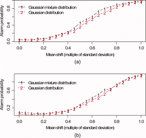
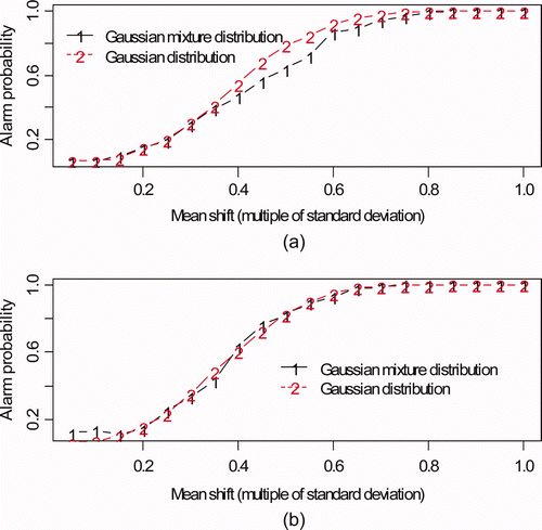
plots the alarm probability (AP) using Crosiers' bivariate cusum [Citation4] versus mean shift for the (a) input accountability tank to buffer tank (see a and b) and (b) buffer tank to control tank (see c and d). The mean shift persisted for 30 batches and was constant in magnitude ranging from 0.05 to 1 times the volume TD standard deviation and the mass TD standard deviation, for a total mean shift (loss) over the 30 batches of 1.5–30 times the volume and mass TD standard deviation. The alarm threshold was empirically chosen to give a false alarm probability (FAP) per 30 batches of 0.05. Because of the multiple tests per tank, the FAP will probably be set much lower [Citation2,Citation7,Citation25], but using 0.05 is adequate to illustrate that effect of having this particular mixture distribution modeled by a single-component standard normal.
Figure 4. Alarm probability versus mean shift. The mean shift persisted for 30 batches and was constant in magnitude ranging from 0.05 to 1 times the volume TD standard deviation and the mass TD standard deviation. (a) Input accountability tank to buffer tank (see Figure 1a and b); (b) buffer tank to control tank (see Figure 1c and d).
is based on 1000 realizations from the estimated density (via kde2e) of the mixture distribution in Equation (1), so simulation error is negligible.
Remark: The terms DP and alarm probability (AP) are almost interchangeable. However, in figures such as in which a true loss of 0 units is included, the term AP is preferred because when the true loss is 0, the alarm is not a “detection” but is a false alarm.
and are the same as , but are for tank 1 (IAT) and tank 3 (buffer) wait modes. is the same as , but is for the wait mode for tank 1 (IAT) and tank 3 (buffer).
Figure 5. Input tank wait mode: (a) Percent volume relative change during the tank 1 (IAT) wait modes for each of 1000 batches; (b) Estimated probability density of the percent volume relative change.
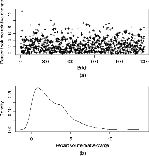
Figure 6. Buffer tank wait mode: (a) Percent volume relative TD during the tank 3 (control) wait modes for each of 1000 batches; (b) Estimated probability density of the percent volume relative change.
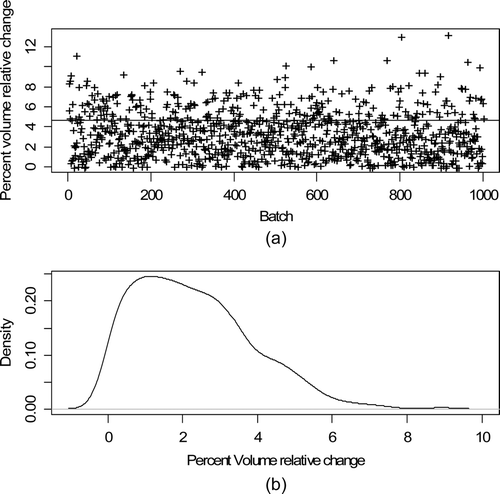
Figure 7. Alarm probability versus mean shift. The mean shift persisted for 30 wait modes and was constant in magnitude ranging from 0.05 to 1 times the volume change standard deviation and the mass change standard deviation. (a) Input accountability tank. (b) Buffer tank.
An important practical consideration is to assess how many wait and transfer modes must be observed in order to set alarm thresholds and to assess detection probabilities.
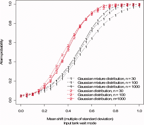
is same as a (based on 1000 simulated wait modes) except is based on 30, 100, or 1000 simulated wait modes for the input and buffer tank.
Figure 8. Alarm probability versus mean shift, same as Figure 7 (a) (input accountability tank), but based on 30, 100, or 1000 training observations. The mean shift persisted for 30 wait modes and was constant in magnitude ranging from 0.05 to 1 times the volume change standard deviation and the mass change standard deviation.
The procedure to assess the impact of a small sample size such as 30 is as follows.
| 1. | Use kde2d in R to estimate the bivariate density f(m,v) from a random sample of n = 30 (M,V) pairs (either change during wait mode or TD during transfer mode). | ||||
| 2. | Use the estimated bivariate density f(m,v) to simulate 30 (M,V) pairs. The density f(m,v) is computed on a fine grid of (M,V) values which are chosen with probabilities proportional to the density at each value. | ||||
Because kde2d is a smoothed histogram, this procedure allows different realizations to have somewhat different (M,V) values than in the original sample of 30 (M,V) pairs.
On the basis of we note that if we use only 30 wait modes, there will be non-negligible effects of small sample size. When we increased from 30 to 100 wait events, results were more similar to results for 1000 wait events (for both the input accountability tank as shown in , and for the buffer tank wait mode, results not shown) so on the basis of this limited study, we require approximately 100 or more events to adequately estimate alarm thresholds and assess detection probabilities.
6.1. Data collection frequency effects
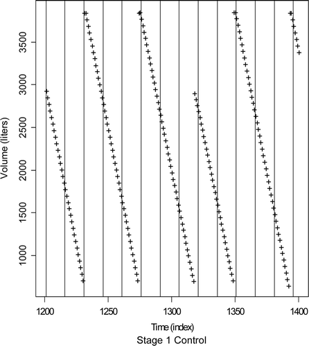
Data collection frequency impacts the error in marking either transfer or wait modes. For example, illustrates the impact of data collection frequency on event marking for the control tank from . The vertical lines depict possible data collection times. Notice that the maximum of some fill cycles is not directly observed (such as the one near time index 1320 or index 1400), and so infrequent data collection will add considerable error to event marks. The AP results in , 7, and 8 did not explicitly consider data collection frequency because it was fixed at 1 min. However, data collection frequency impacts the behavior of PV 2 in Equation (1), and the assumed frequency for all quantitative results presented was every 1 min (by linear interpolation of the original 5-min data and 1-min data was available).
Figure 9. The impact of data collection frequency on event marking for the stage 1 control tank. The vertical lines depict possible data collection times. Notice that the maximum of some fill cycles is not directly observed (such as the one near time index 1320 or near index 1400.
Generally, more frequent data collection improves APs, at least for the types of transients considered here.
7. Real data example
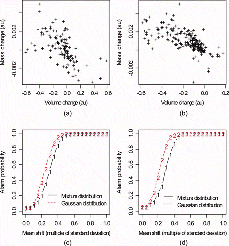
is L readings in arbitrary units from tanks at Savannah River Site during May 2005. a is tank 17-2 and b is tank B3-1. c and d plot the percent relative rate of change in volume (defined as the volume change divided by the duration of the wait mode) for wait modes for each tank during 2005. Notice the patterns in the relative rate of change. For example, there is very little change during the first 10 or so wait modes for tank 17-2 (10c). The relative rate of change accounts for the duration of the wait mode and appears to be more consistent than the relative change (not shown). a is the estimated density for the relative rates of change in volume for tank 17-2 in c. Bimodality is evident (notice the small rise in density near a relative rate of change of 2 in a). b is a normal probability plot, which should be approximately linear if the data are independent normal (L changes during wait modes should be approximately independent because systematic errors which lead to non-independence will cancel or nearly cancel). c and d are the same, but are for tank B3-1. plots (M,V) pairs for (a) 129 and (b) 208 wait modes for tank B3-1 and E4-2. sub-plots (c) and (d) plot the estimated AP versus mean shift as in a, but for the data in (a) and (b). In both cases, the Gaussian approximation overestimates the AP compared to estimates using density estimation applied to the real (M,V) pairs.
Figure 10. Real data example. Normalized level in arbitrary units (au) versus time for two tanks at Savannah River Plant during 2005 (99 and 73 wait modes, respectively). (a) May 2005: tank 17-2. (b) May 2005: tank B3-1. (c) May 2005: tank 17-2. (d) May 2005: tank B3-1.
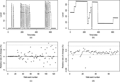
Figure 11. Estimated density and normal probability plots of the relative rates of change in (a) Tank 17-2 wait mode. (b) Tank B3-1 wait mode.
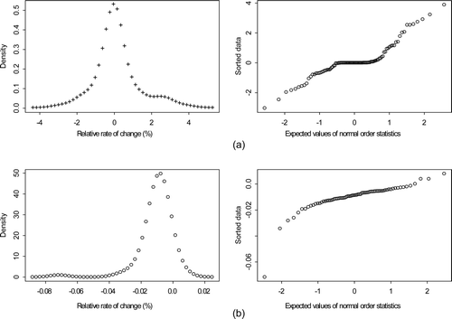
Figure 12. Mass, volume pairs for (a) tank B3-1 and (b) tank E4-2 during 129 and 208 wait modes. Estimated AP versus mean shift for (c) tank B3-1 and (d) tank as in Figure 7a where the mean shift persisted for 30 wait modes and was constant in magnitude ranging from 0.05 to 1 times the volume change standard deviation and the mass change standard deviation.
Real data examples are currently available to us from three aqueous facilities. As discussed in previous sections, such real data help to add realism to corresponding simulated data. For example, (top) is more realistic simulated true L readings which we denote μ t . These true readings in arbitrary units (au) do not include any measurement error but do illustrate most of the challenges we consider, including the presence of: (1) many change rates and change durations; (2) different spacings between events; (3) nuisance high-noise subevents or outliers; (4) break or bend points in true signals that arise due to solution transfer rates changing; and (5) inconsistent event signatures. Events labeled A are typical receipt/ship events. Event B is also a receipt/ship event but the shipment is interrupted before completion and there is evaporation during the “wait” mode. Event C is a sparging/agitation event. Events D are two sets of erratic measurements due to instrument faults (outliers). Event E is a recirculation event.
Figure 13. Example of different batches (simulated data without measurement error).
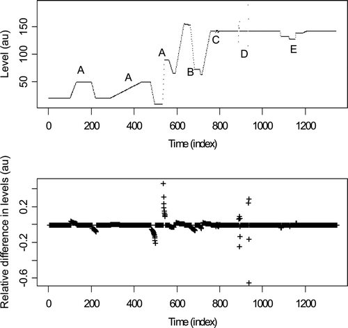
The term “noise” can refer to either measurement error or to nuisance changes in true tank level μ t such as occur in sparging/agitation or temporary instrument faults.
(top) suggests that the true levels in the real data can be well modeled as piecewise linear or constant (as was assumed for the simulated data). Of course any function observed at discrete time steps is piecewise linear, but the pieces in our applications are relatively long time sections reflecting tank activity or inactivity.
Measured readings yt will have some type of measurement errors present, and there could be both relative and absolute errors so for example yt = μ t (1 + RR ,t ) + RA ,t where RR ,t is the relative random measurement error at time t and RA ,t is the additive measurement error at time t. The bottom plot in is the relative lag − 1 (using only the values at t and t − 1) differences dt = (yt − yt− 1)/y t = (μ t – μ t − 1)/μ t in the case of zero measurement error. The simplest change detection method considered in Burr et al. [Citation7] is based on such lag − 1 differences. We need to mark the start and stop times for each event and lag − 1 differences are used in one option to locate events. As mentioned in discussing Equation (1), event marking errors e marking are included in Equation (1) and the standard deviation of e marking can be characterized via simulation.
8. Discussion
Previously reported [Citation2,Citation6] detection probabilities (DPs) based on simulated data are probably somewhat optimistic. In this article, DPs have been estimated when realistic effects are included in the simulated data, such as pump and pipe carryover in transfer modes, evaporation and/or condensation in wait modes. These realistic effects lead to mixture probability densities. And, DPs were estimated in corresponding variance-inflated single-component (single mean) Gaussian probability densities to evaluate the impact of using a wrong but “reasonable” probability density. Using this “reasonable” but wrong probability density can lead to either over-estimating or under-estimating desired tail probabilities. As an aside, Burr and Howell [Citation6] estimate DPs in simulated data that assumes single-component and lower variance Gaussian probability densities than considered here. Not surprisingly, these DPs are higher (more optimistic) than those presented here.
DPs were also estimated in real tank data ( and ). illustrates simulated evaporation during wait modes and mixing/sparging. Ideally, a SM system would ignore mixing/sparging because it occurs during “wait” modes, but the SM system should check every wait mode for M and V changes as illustrated. Therefore, if diversion occurs during sparging, it is potentially detected in the wait model monitoring. Instrument faults raise another “issue,” and Howell et al. [Citation26] illustrate an approach requiring inspector interaction to resolve anomalies that are most likely caused by temporary instrument faults. If Crosier's bivariate cusum alarms due to an instrument fault in one tank, the goal is to flag the alarm, resolve it, archive the “event,” make the event archive available to the International Atomic Energy Agency (IAEA), but not require that any such resolved non-safeguards “events” be reported to the IAEA in order to avoid information overload.
In the SM context, it is unlikely that a single component bivariate normal approximation for (M,V) can be chosen that works either on any given tank or tank pair or “on average” across multiple tanks or multiple shipper-receiver tank pairs. It is safer to separately analyze each tank and tank pair for suitable alarm thresholds, and to estimate the bivariate density using kde2d rather than assume a bivariate normal distribution. However, as a rough approximation in some contexts, it might be adequate to continue to assume a bivariate normal distribution for (Mroman V) pairs that are monitored during each tank's wait and transfer modes. One concern here is the possible need for very low per-event and per-tank false alarm rates which requires accurate probability estimation in the tails of the actual distribution. Another concern is that this rough approximation will be biased low in some cases and high in other cases, so unless each tank and tank pair were actually evaluated in training data, it would not be possible to assess the quality of the rough approximation.
9. Summary
Previous loss DP estimates for SM evaluation systems were known to be optimistic [Citation7]. Here we revised the DP estimates based on larger variances in the V and M TDs in transfers and V and M changes during wait modes. Because real data can exhibit non-normal behavior, partly explainable by process variation leading to a mixture distribution, we simulated effects that lead to mixture distributions. We compared estimated loss DPs arising from these mixtures and arising from the usual approximating single-component standard normal.
We did not find a consistent pattern relating the DPs from mixtures to the DPs from single-component standard normal distributions. Although it appears more common that the DPs based on single-component standard normal distributions are optimistically higher than those from mixtures, a general trend is missing (compare – for example). Therefore, simulation is required to set thresholds, and perhaps to choose good alarm rules. Choosing optimal alarm rules was neither considered here, nor was the possibility of monitoring solution flow rates with pump monitors [Citation27].
Future work will include: (1) options to control family wise FAPs in multiple testing [Citation25]; (2) link Crosier's bivariate cusum monitoring with anomaly resolution. As an example, Crosier can/should alarm on a sensor fault, but the alarm should be resolved as a “nonsafeguards issue;” (3) further investigate option (2) involving monitoring transfer and nontransfer modes, including a detailed evaluation of the expected number of statistical tests by tank per inspection period; (4) current efforts to quantify SM benefits have focused almost entirely on operator loss DP [Citation20]; extend evaluations to inspector loss DP by considering the possibility of self-authentication of SM data and suggesting inspector activities; (5) investigate mixing rules to provide short cut but essentially continuous nuclear material assay by tracking Pu mass in addition to tracking bulk solution mass as presented here; and (6) as in Burr et al. [Citation2], bias adjustments based on historical data could reduce the RSDs reported here.
Acknowledgments
The authors wish to thank the US DOE and NNSA (NA-22 and INSEP) support programs for sponsoring this work.
Related Research Data
References
- Ehinger , M. , Chesnay , B. and Creusot , C. Solution monitoring applications for the Rokkasho reprocessing plant . Seventh International Conference on Facilities Operations–Safeguards Interface, American Nuclear Society . Charleston , SC
- Burr , T. , Coulter , A. and Howell , J. 2003 . Solution monitoring: quantitative and qualitative benefits to safeguards . J. Nucl. Sci. Technol , 40 : 256 – 263 .
- Burr , T. , Ehinger , M. and Howell , J. A review of process monitoring for safeguards . Eighth International Conference on Facility Operations–Safeguards Interface . March 30–April 4 . Portland, OR available on CD-ROM or from [email protected]
- Burr , T. , Hamada , M. and Howell , J. 2008 . Multivariate statistical process monitoring options for solution monitoring, LA-UR-08-06290 Los Alamos National Laboratory Unclassified Report available at [email protected]
- Burr , T. , Howell , J. , Suzuki , M. , Crawford , J. and Williams , T. Evaluation of loss detection methods in solution monitoring for nuclear safeguards . American Nuclear Society Conference on Human–Machine Interfaces . Knoxville, TN
- Burr , T. , Howell , J. and Bevan , G. The performance of current solution monitoring evaluation systems approaches in best cases . Proceedings of 49th Annual Meeting of the Institute of Nuclear Materials Management . Nashville, TN
- Burr , T. , Suzuki , M. , Howell , J. , Longo , C. and Hamada , M. 2011 . Signal estimation and change detection in solution monitoring for safeguards . Nucl. Instrum. Methods Phys. Res. A , 640 : 200 – 221 .
- Howell , J. , Ehinger , M. and Burr , T. 2007 . Process monitoring for safeguards, LA-UR-07-7305 Los Alamos National Laboratory Unclassified Report available at [email protected]
- Howell , J. and Bevan , G. 2008 . The contribution of solution monitoring to reprocessing safeguards, University of Glasgow Technical report available at [email protected]
- J. , Howell . 2008 . Methods and algorithms for tank monitoring evaluation systems SRDP-R302, UK D01363, UK safeguards support for the IAEA report, Technical report available from J. Howell upon request
- Suzuki , M. and Burr , T. A study on loss detection algorithms for tank monitoring data using multivariate statistical analysis . Proceedings of 29th Annual Meeting of INMM Japan Chapter . Tokyo , , Japan available at [email protected]
- M. , Suzuki , Hori , M. , Nagaoka , S. and Kimura , T. 2009 . A study on loss detection algorithms using tank monitoring data . J. Nucl. Sci. Technol , 46 : 184 – 192 .
- M. , Ehinger , Zack , N. and Franssen , F. 1991 . Use of process monitoring for verifying facility design for large-scale reprocessing plants Los Alamos National Laboratory Unclassified Report, LA-12149-MS, ORNL 11856
- Richir , P. , Dechamp , L. , Janssens-Maenhout , G. , Holzleitner , L. , Janssens , W. , Schwalbach , P. , Casteleyn , K. and Duinslaeger , L. Data analysis and interpretation software from solution monitoring towards near real time accountancy . Proceedings of 47th Annual Meeting Institute of Nuclear Materials Management . Nashville, TN
- R. , Binner , Howell , J. and Jahssens-Maenhous , G. 2008 . Practical issues relating to tank volume determination . Process Des. Control Ind. Eng. Chem. Res , 47 : 1533 – 1545 .
- Howell , J. 2009 . Towards the re-verification of process tank calibrations . Trans. Inst. Meas. Control , 31 : 117 – 128 .
- Miller , E. and Howell , J. 1999 . Tank measurement data compression for solution monitoring . J. Nucl. Mater. Manage , 28 : 25 – 33 .
- Burr , T. Solution monitoring scoring systems . Proceedings of 50th Annual Meeting Institute of Nuclear Materials Management . Tucson, AZ
- Aigner , H. 2002 . International target values 2000 for measurement uncertainties in safeguarding nuclear materials . J. Nucl. Mater. Manage , 30 available at www.inmm.org/topics/publications
- Burr , T. , Ehinger , M. , Howell , J. and Pomeroy , G. Reducing inspector uncertainty via solution monitoring . Proceedings of 48th Annual Meeting Institute of Nuclear Materials Management . Tucson, AZ
- Howell , J. and Scothern , S. 1997 . A prototype diagnostic aid for a tank monitoring system UK Safeguards R&D, SRDP-R244, Technical report available from J. Howell upon request
- 2004 . R Core Development Team software available at http://www.r-project.org
- Burr , T. , Foy , B. , Fry , H. and McVey , B. 2006 . Characterizing clutter in the context of detecting weak gaseous plumes in hyperspectral imagery . Sensors , 6 : 1587 – 1615 .
- Venables , W. and Ripley , B. 1999 . Modern Applied Statistics with Splus , New York : Springer .
- Romano , J. and Wolf , M. 2005 . Exact and approximate stepdown methods for multiple hypothesis testing . J. Am. Stat. Assoc , 100 : 94 – 108 .
- Howell , J. , Burr , T. and Ehinger , M. The inspector interface in solution monitoring systems . Proceedings of 50th Annual Meeting Institute of Nuclear Materials Management . Tucson, AZ
- Burr , T. , Hamada , M. and Howell , J. Measurement error modeling and simulation for solution monitoring . Proceedings of 49th Annual Meeting Institute of Nuclear Materials Management . Nashville, TN