Abstract
Sodium-water reaction (SWR) in a steam generator of sodium-cooled fast reactor (SFR) is a significant phenomenon for safety assessment of the system. One of the top concerns in the SWR is an overheating rupture phenomenon in which a neighbor heat transfer tube fails instantaneously because of a deterioration of structural integrity under a high temperature condition. Hence, the heat transfer coefficient on the tube surface is of importance. Since hydrogen gas is generated in the SWR and liquid water will evaporate quickly due to depressurization, the reaction region is covered with a multi-phase flow structure, and thus the value of the heat transfer coefficient will vary widely. In the present paper, a correlation diagram has been developed between the heat transfer coefficient and the void fraction based on one dimensional homogeneous flow simulation. Furthermore, the transient of void fraction in SWAT-1R experiment is investigated using the diagram.
1. Introduction
Sodium-water reaction (SWR) is a significant phenomenon for safety assessment of sodium-cooled fast reactor (SFR). It will take place at a steam generator (SG) of SFR when water/steam leaks from a heat transfer tube into the shell side of the SG in which liquid sodium flows. Since the SWR generates a large amount of reaction energy and an alkaline reaction product, such as a sodium hydroxide and sodium oxide, a neighbor heat transfer tube might fail caused by wastage and overheating rupture phenomena when it is covered with the reaction jet. The neighbor tube is damaged by erosion and corrosion in case of the wastage phenomenon, while a deterioration of structural integrity due to high temperature of the reaction jet causes the overheating rupture.
One of the important issues in the SWR is that the overheating rupture will take place immediately once the tube temperature reaches a certain level because water/steam is highly pressurized inside the tube. In 1987, the SWR accident was happened at the super heater of the Prototype Fast Reactor (PFR) in UK. In that accident, it was reported that 39 over heating ruptures occurred within 10 s [Citation1]. Accordingly, an evaluation of heat transfer tube's temperature covered by the reaction jet is a key issue to predict a probability of overheating rupture and thus a heat transfer coefficient is of importance upon the overheating rupture phenomena.
Since the reaction jet region consists of liquid (sodium and sodium hydroxide) and gas (steam and hydrogen), a magnitude of heat transfer coefficient at the tube surface will vary widely due to its physical properties such as a velocity and a void fraction. The authors have investigated the heat transfer coefficient based on SWAT-1R experiment [Citation2] in the previous work [Citation3].
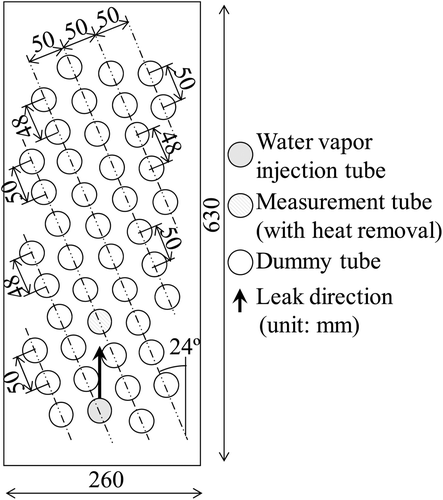
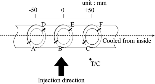
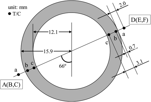
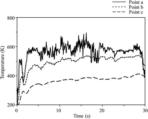
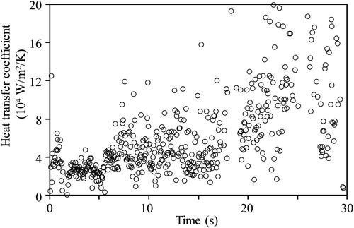
In SWAT-1R experiment, 43 tubes were installed as shown in and steam of 620K and 17.0 MPa was leaked into liquid sodium vertically upward at approximately 0.3 kg/s and the temperature transients were measured at the measurement tube (gray colored tube in during the experiment. shows the location of the temperature measurement. There are six locations (Location A to F) at the measurement tube and each location consists of three thermo-couples (T/C). The position of T/C and the temperature transient measured in the experiment are summarized in and respectively. As a result of the authors’ previous work [Citation3], the heat transfer coefficient has been evaluated in the range of 15,000-128,000 W/m2/K as shown in and . In the SWR, it was observed that the maximum temperature exceeded 1300 K [Citation2] where the deterioration will be initiated. Taking into account the boiling point of liquid sodium (approximately 1150 K at atmospheric condition), the high temperature region will consist of the gas phase dominantly that will result in a comparative small magnitude of the heat transfer coefficient rather than that in liquid dominant flow. Hence, it is necessary to estimate the void fraction near the tube so that one obtains the heat transfer coefficient and predicts the probability of the overheating rupture in detail.
Table 1. Heat transfer coefficient.
In the present paper, a correlation diagram between the void fraction near heat transfer tube and the heat transfer coefficient on the tube surface has been developed so as to estimate the heat transfer coefficient precisely. For this purpose, one dimensional thermal hydraulics simulation based on a homogeneous fluid and boundary layer approximation analysis has been carried out. A velocity of outermost boundary and an average void fraction in homogeneous fluid are chosen as a parameter in the analysis. Furthermore, the void fraction transient process in the SWAT-1R experiment has been also investigated using the developed diagram.
2. Development of correlation diagram between heat transfer coefficient and void fraction
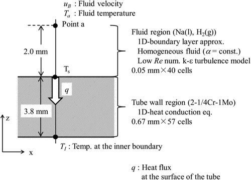
shows the analytical region. The upper boundary of the fluid region is 2 mm above the tube surface that corresponds to the same position with T/C-a (see ). Since the fluid region exists only near the tube surface, a boundary layer approximation [Citation4,Citation5] is applied as a numerical method.
As the result of the experimental and the mechanistic approach using molecular orbital method [Citation6], it is concluded that the dominant reaction of SWR is given as
The rate of steam inlet is approximately 0.3 kg/s. Hence, the generation of the hydrogen gas is estimated approximately 0.017 kg/s. As mentioned in the introduction, the reaction jet region consists of two phase flow. As a result of numerical simulation of SWAT-1R experiment by SERAPHIM code [Citation6], it was demonstrated that the measurement tube was covered by liquid sodium and hydrogen gas dominantly. Hence, liquid sodium and hydrogen gas are considered as a working fluid in the analysis.
Taking into account a wettability of liquid sodium on stainless-steel, a liquid film of sodium might appear at the tube surface during the experiment. Thus, a void fraction would not be constant near the tube surface. In that situation, the tube temperature will not exceed the boiling point of sodium although a high temperature (over 1300K) is achieved outside the liquid film. Accordingly, a homogeneous fluid model is assumed in the present analysis from the viewpoint of both a simplified and conservative estimation.
In the numerical simulation by SERAPHIM, it was also demonstrated that a comparative high velocity was investigated near the measurement tube. Therefore, a low Reynolds k– ϵ turbulent model [Citation7] is implemented. It is mentioned that the present set of numerical method are the same with the previous work [Citation5] in which the heat transfer coefficient on the tube surface is estimated directly from the numerical simulation. In the analysis, the fluid velocity and the void fraction nearby the heat transfer tube surface are given parametrically as the boundary condition. As a result, the correlation diagram between the heat transfer coefficient and the void fraction has been developed.
2.1. Numerical procedure
In the boundary layer approximation theory [Citation4,Citation5], a tangential velocity profile is evaluated with a space derivative of non-dimensional flow stream function f ′. The tangential velocity in the boundary layer ux is evaluated using boundary velocity u B as
The governing equations of mass, momentum and energy are described respectively as
where t is the time. x and z mean the tangential and vertical to the surface coordinates, respectively. u z is the velocity vertical to the tube surface. ρ, p and T mean the density, the pressure and the temperature of the mixture gas, respectively. ν, λe and Cp are the dynamic viscosity, the thermal conductivity and the specific heat of the mixture fluid. νt, and αt are the turbulent viscosity and the turbulent thermal diffusivity, respectively.
In the low Reynolds number k-ϵ turbulence model [Citation7], the equations for turbulence energy k and the energy dissipation ratio ϵ are given as
where C 1 and C 2 are the constant decided empirically and are set to 0.09 and 1.44. σk and σϵ are the constants as the turbulent Prandtl number and are set to 1.0 and 1.3. τ is the turbulent time scale used in this model and written as
The νt is calculated in following equation:
where C μ is an empirical constant and set to 1.92. The model function in the turbulent number f μ is given as
The variable number R z is written as
The numerical constants a 1, a 3 and a 5 are set to 1.5 × 10⁻⁴, 5.0 × 10⁻⁷ and 1.0 × 10⁻¹⁰, respectively. The turbulent thermal diffusivity αt is described as
where Pr t means the turbulent Prandtl number and is set to 0.9.
In Equation (5), a volumetric average is considered in terms of the density and the specific heat. On the contrary, an effective thermal conductivity should be taken into account instead of the volumetric average. For instance, the following Davis's equation [Citation8] was applied in the previous work [Citation5].
where λc is the thermal conductivity of continuous phase, p is the ratio of the thermal conductivity of the dispersed phase to λc, and f c is the volume fraction of the continuous phase.
Equation (13) is obtained based on a theoretical analysis where a spherical shape of dispersed phase is assumed. To develop the equation, it is also assumed that the void fraction of the continuous phase is quite large. Additionally, the continuous phase is replaced by the dispersed phase when the void fraction becomes small. However, the displacement is not considered in the equation. Therefore, the accuracy of the evaluation of the effective thermal conductivity becomes small when the void fraction is small.
Nield [Citation9] also proposed an empirical correlation as:
where λd is the thermal conductivity of the dispersed phase.
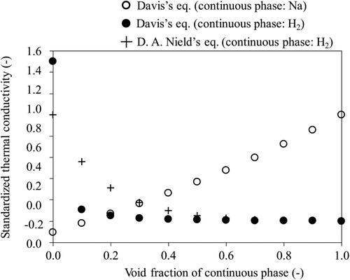
shows the comparison of the effective thermal conductivity, in which liquid sodium and hydrogen gas are considered as a component of mixture fluid, between Equations (13) and (14). In , the effective thermal conductivity is normalized as
In the Nield's model, the effective thermal conductivity at high volume fraction (f c ≫ 0.5) is similar with the Davis's equation (continuous phase: H2). In case of the low volume fraction, it becomes an intermediate value of the Davis's equations. In the present analysis, two models are examined. One is the Davis's model in which the continuous phase is exchanged at f c = 0.5 so as to eliminate the unpractical value. The other is the Nield's model. The influence of the effective conductivity will be discussed in the next section. As concerns the tube structure region, the following one dimensional equation of heat conduction is solved.
The subscript st means the structure (heat transfer tube).
2.2. Development of correlation diagram
The analytical region is divided equally into 40 and 57 computational cells for the fluid and tube wall regions respectively as shown in . In the analysis, the boundary temperatures at both ends of the analytical region (T a and T I in ) are set to 1173 K for T a and 773 K for T I based on SWAT-1R experiment (). The boundary velocity (u B) and the average void fraction (α) are chosen as a parameter in order to obtain the diagram.
Firstly, the boundary velocity is given. Then a parametric analysis of the average void fraction is carried out. In each simulation, the heat flux on the surface (q) is calculated by adjoining two computational cells’ temperature and thermal conductivity after a steady state is achieved. Next, the tube surface temperature T s is evaluated using the heat flux and the steady state heat conduction equation. Finally, the heat transfer coefficient is obtained based on the heat flux, T a and T s. The heat transfer coefficient is written as
With regard to the boundary velocity, three cases of 0.5, 1.0 and 1.5 m/s are selected based on the previous work [Citation5].
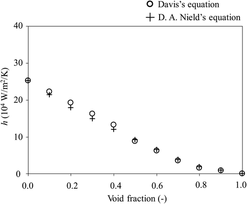
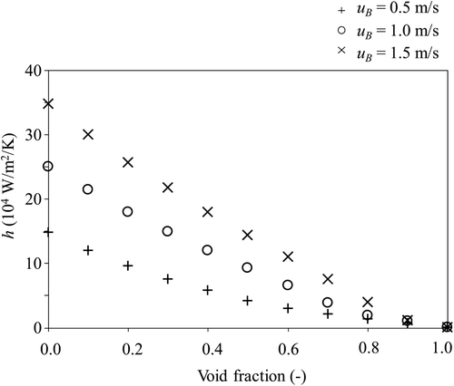
shows the comparison of the diagram between the effective thermal conductivity models. In the analysis, the boundary velocity is set to be 1.0 m/s. As shown in , the effective thermal conductivity model has a little influence on the diagram. This is attributed the fact that the turbulent thermal diffusivity becomes much larger than the molecular thermal diffusivity. Taking into account the simplicity and the practical value through all range of the void fraction, the Nield's equation (EquationEquation 14) is applied in the following analysis.
The influence of the boundary velocity on the diagram is shown in . When the void fraction is high (α > 0.8), almost similar value of the heat transfer coefficient is obtained as seen in . On the other hand, the boundary velocity has much influence on the heat transfer coefficient if the void fraction is lower than 0.8. From the viewpoint of overheating rupture possibility, the high temperature region (>1300 K) is important and will exists in a high void fraction region considering the boiling point of sodium. Consequently, the boundary velocity might be less influential in terms of the overheating rupture possibility.
3. Investigation of void fraction in SWAT-1R experiment
An investigation of the void fraction transient in SWAT-1R experiment is carried out using the present diagram in order to investigate an applicability of the diagram. Since there was no measured data in terms of the velocity near the T/C, the diagram of u B = 1.0m/s is applied firstly to the transient of the heat transfer coefficient investigated in the authors’ previous work [Citation3] (for instance, ). It is mentioned that some data of heat transfer coefficient is eliminated in the conversion into the void fraction when it exceeds the range of the diagram.
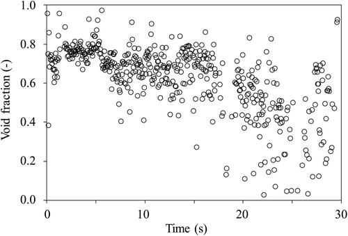
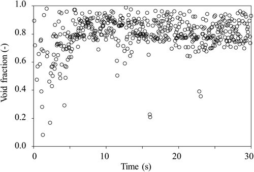
and show the transient of the void fraction at Location A and E, respectively. A median value and its standard deviation at each location are summarized in . As discussed in the previous work [Citation3], a comparative high void fraction (>0.7) is investigated at Location A from the beginning of the leakage as seen in .
Table 2. Void fraction and standard deviation.
Location A is located at comparatively lower side of the tube and faced to the leakage (). The void fraction reached larger than 0.7 (, ) and the oscillation is not large in the initial 5 s. Hence, it is expected that the reaction jet covered the location quickly and the gas phase existed stably around Location A. Consequently, the void fraction is evaluated quasi-steady state until 18 s. After that, the void fraction decreases lower than 0.6 and fluctuates widely. This indicates that the fluid condition changed after 18 s. Probably, the interface of reaction jet region would cover over Location A at that duration. Meanwhile, the Location E is set at the upper side of the tube. At Location E, the void fraction oscillates significantly at the beginning of the leakage (). Hence, it is expected that the reaction jet was developing and the fluid state was unsteady in this time period. However, a constant void fraction of approximately 0.8 is achieved after 5 s as in . It could be said that the reaction jet appears stably at Location E after 5 s.
Let us discussed the magnitude void fraction especially when it achieves a comparative steady state (> 0.7). Kudoh et al. [Citation10] measured the distribution of void fraction around a horizontally located single rod. In the experiment, argon (Ar) gas was blowed upward vertically into liquid sodium at 25 mm far from the bottom of the rod. The average velocity of Ar was set to approximately 100–350 m/s and the circumferential distribution of the void fraction was measured at 1–4 mm above the rod surface. As an example, the experimental result is shown in (173 m/s of inlet velocity). In the experiment, it was demonstrated that the rod would be covered over Ar gas and the void fraction is around 0.6 to 0.9 at 1 and 2 mm above the tube surface. In SWAT-1R experiment, a critical flow (several hundred m/s) was achieved at the leakage that is set at approximately 100 mm far from the measurement tube (). It is difficult to compare the velocity magnitude around the tube between SWAT-1R and Kudoh's experiments. However, a comparative high inlet velocity was applied in Kudoh's experiment and thus it is said that the present investigation would have a consistency with the measurement profile.
Figure 12. Void fraction profile around a single rod in sodium pool [Citation10].
![Figure 12. Void fraction profile around a single rod in sodium pool [Citation10].](/cms/asset/cc6084ce-4829-4921-a6f9-3210be9f9fba/tnst_a_686810_o_f0012g.gif)
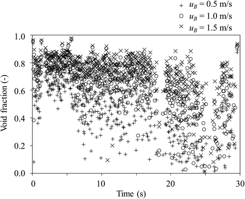
shows the influence of the boundary velocity in the diagram (u B) on the investigation of the void fraction at Location A. During first 5s, the void fraction varies from approximately 0.6 to 0.9 as u B changes. However, it is almost in the range of Kudoh's experiment as mentioned above. After 5 s, the distribution of the void fraction dispreads widely regardless of u B. In the present investigation, it is commonly said that the standard deviation becomes large when the median value of the void fraction becomes small as shown in . In the experiment, the temperature was measured by T/C. Hence, the uncertainty of the measurement will be enlarged especially when non-equilibrium between liquid and gas phases state is developed under a low void fraction condition. Consequently, the present result of the low void fraction investigation will have a large uncertainty, which comes not only from the uncertainty of the diagram (influence of u B) but also from the uncertainty of temperature measurement. When the high temperature gas phase heats liquid sodium, evaporation of liquid sodium would be started and the void fraction of the fluid would become large. Hence, it is expected that most of the high temperature fluid consist of the gas phase. Meanwhile, comparatively small void fraction fluid includes liquid phase which have lower temperature than the boiling point of liquid sodium. Therefore, it is expected that the temperature of the low void fraction fluid is not so high. Therefore, it is again noted that an overheating rupture phenomenon will not be taken place in a low void fraction condition because of the boiling temperature of liquid sodium and thus the uncertainty of the diagram may not be influential in terms of the prediction of overheating rupture.
4. Conclusions
In the present study, the correlation diagram between the heat transfer coefficient and the void fraction has been developed in order to enhance a predictability of an overheating rupture occurrence. One dimensional thermal hydraulics simulation based on a homogeneous fluid and boundary layer approximation analysis has been carried out for this purpose. The influences of the models in the effective thermal conductivity and of the boundary velocity conditions on the diagram have been investigated. As a result, it is demonstrated that the models of the thermal conductivity effects a little on the diagram. Considering the practical thermal conductivity, the Nield's equation would be appropriate.
As concerns the influence of the boundary velocity, it influences on the diagram if the void becomes small, while the influence is small when the void fraction is large (α > 0.8). Taking into account a predictability of overheating rupture occurrence, the high temperature region, which will appear at the high void fraction region, is of concern. Hence, the boundary velocity will have less influence from the viewpoint of the prediction.
The transient of the void fraction in SWAT-1R experiment has been carried out and the applicability of the diagram has been discussed. When the void fraction is estimated to be comparative high (>0.7), the fluctuation of the fraction weakens comparing with that in lower void fraction case. Probably, a stable gas dominant jet region would exist in the experiment. The range of the high void fraction evaluated in the present study agrees almost with the measurement result by Kudoh.
The uncertainty of the diagram that comes from the uncertainty of the boundary velocity (u B) increases in case of a low void fraction estimation. However, the uncertainty of the temperature measured by T/C also increases in case of the low void fraction. Furthermore, the overheating rupture would not be taken place in that situation because of the boiling point of liquid sodium. Hence, it is concluded that the developed diagram would be useful to investigate the overheating rupture, although it has uncertainty in terms of the determination of the boundary velocity. It is also noted that the present diagram is efficient when it is coupled with a numerical investigation of the SWR, such as SERAPHIM code because the boundary velocity is estimated easily in the numerical simulation.
Nomenclature
| C p | = |
Specific heat J/kg/K |
| C μ | = |
Empirical constant |
| f ′ | = |
Space derivative of non-dimensional flow stream function |
| f c | = |
Volume fraction of continuous phase |
| k | = |
Turbulence energy m2/s2 |
| P | = |
Ratio of the thermal conductivity of the dispersed phase to λc |
| Pr t | = |
Turbulent Prandtl number |
| Q | = |
Heat flux W/m2 |
| T | = |
Temperature K |
| t | = |
Time s |
| ux | = |
Tangential velocity m/s |
| u B | = |
Boundary velocity m/s |
| uz | = |
Velocity vertical to the wall m/s |
| x | = |
Vertical to the wall direction m |
| z | = |
Tangential to the wall direction m |
Greek Letters
| α | = |
Void fraction |
| αt | = |
Turbulent thermal diffusivity m2/s |
| λc | = |
Thermal conductivity of the continuous phase W/m/K |
| λd | = |
Thermal conductivity of dispersed phase W/m/K |
| λe | = |
Effective thermal conductivity W/m/K |
| λs | = |
Thermal conductivity of tube wall W/m/K |
| ν | = |
Dynamic coefficient of viscosity m2/s |
| νt | = |
Turbulent viscosity m2/s |
| ρ | = |
Density kg/m3 |
| ϵ | = |
Turbulence energy dissipation ratio m2/s3 |
Additional information
Notes on contributors
Toshinori Matsumoto
†Present address: Japan Atomic Energy Agency, Nuclear Safety Reserch Center, 2-4 Shirane, Shirakata, Tokai-mura, Naka-gun, Ibaraki, JapanReferences
- Currie , R. , Linekar , G.A.B. and Edge , D.M. The under sodium leak in the PFR superheater 2 in February 1987 . Proceedings of the Specialists’ Meeting on Steam Generator Failure and Failure Propagation Experience . pp. 107 – 132 . France
- Nishimura , M. , Shimoyama , K. , Kurihara , A. and Seino , H. Sodium-water reaction test to confirm thermal influence on heat transfer tubes . JNC Tech. Rep . TN9400-2003-014 (JNC) . [in Japanese]
- Matsumoto , T. , Takata , T. , Yamaguchi , A. , Kurihara , A. and Ohshima , H. 2011 . Estimation of heat transfer coefficient and flow characteristics on heat transfer tube in sodium-water reaction . J. Nucl. Sci. Technol , 48 : 315 – 321 .
- Smooke , M.D. 1992 . Numerical modeling of axisymmetric laminar diffusion flames . Impact Computing Eng , 4 : 46 – 79 .
- Yamaguchi , A. Thermal influence on steam generator heat transfer tube during sodium-water reaction accident of sodium-cooled fast reactor . NURETH-12 . Pittsburgh , PA : USA, September 30-October 4 .
- Takata , T. and Yamaguchi , A. 2003 . Numerical approach to the safety evaluation of sodium-water reaction . J. Nucl. Sci. Technol , 40 : 708 – 718 .
- Yang , Z. 1993 . New time scale based k-e model for nearwall turbulence . AIAA J , 31 : 1191 – 1198 .
- Davis , R.H. 1986 . The effective thermal conductivity of a composite material with spherical inclusions . Int. J. Thermophys , 4 : 609 – 620 .
- Nield , D.A. 1991 . Estimation of the stagnant thermal conductivity of saturated porous media . Int. J. Heat Mass Transfer , 34 : 1575 – 1576 .
- Kudoh , H. , Sugiyama , K. , Narabayashi , T. and Ohshima , H. Void fraction behavior of argon gas jet around a single rod horizontally set in the sodium pool, . NTHAS7 . Chuncheon , , Korea : November 14–17 .
