Abstract
A steam generator at a nuclear power plant consists of thousands of thin tubes, and is a highly important component in operation. Also, steam generator tubes play a critical role in maintaining pressure boundaries of the primary and secondary sides, and can be easily damaged due to operation conditions caused by high temperature and pressure. Therefore, considerable amount of efforts are being committed to evaluating structural integrity of steam generators during in-service inspection. Eddy current testing is the commonly used inspection technique to evaluate a steam generator tube's integrity, but it has limitations in accurately sizing flaws due to the nature of the technique which determines size based on the entire volume of a flaw. In this study, experiments were performed by using ultrasonic testing instead of eddy current testing for the inspection of steam generator tubes to detect various kinds of flaws and to see if the detected flaws can be sized accurately. Consequently, the ultrasonic testing technique could detect various types of flaw, and the flaw sizing results were reliable in length and depth.
1. Introduction
Steam generator tubes at a nuclear power plant are a pressure boundary between the primary side where radioactive materials exist and the secondary side's pressure boundary, which is not contaminated by radioactive materials. A steam generator tube is an important element of a nuclear power plant that can influence entire safety of the plant. More specifically, if a steam generator tube is damaged, radioactive materials on the primary side may leak, leading to a serious accident. In other words, damage or rapture involving a steam generator tube is closely related to the life and output power of a nuclear power plant. So far, several items have been known causing damage to a steam generator tube, and of these, damage to primary water stress corrosion cracking (PWSCC) taking place at the inner diameter, which is the primary side, and outer diameter stress corrosion cracking (ODSCC) at the outer diameter, which is the secondary side account for 60% of all flaws, taking up the biggest portion Citation1. In addition to the aforementioned, steam generators are damaged in various ways including fretting and other fatigue crack, wear, denting and pitting due to its high-temperature and pressure operational conditions. The most frequent damage occurring at steam generator tubes of nuclear power plants in Korea is caused by PWSCC in the primary side and wear. In particular, PWSCC happens when the inner tube is cracked, and the depth of a crack increases toward the outer side alongside the wall thickness. Here, cracks can be divided into those in the axial direction where the length of a crack grows in the direction of a tube's length, and those in the circumferential direction where the length of a crack grows along the circumference of a tube. Both types of cracking at nuclear power plants in Korea have been reported Citation2. In general, inspection of steam generator tubes during in-service inspection of nuclear power plants is currently performed by eddy current testing. While eddy current testing have advantages such as fast inspection speed and convenience, but it is difficult to evaluate accurate sizes of flaw length or depth with this method, because the sizing estimation based on signal amplitude is affected by the flaw's entire volume due to the nature of eddy current testing. Steam generator tube inspection using ultrasonic testing began as part of efforts to develop various inspection methods in order to meet inspection requirements specified by “PWR Steam Generator Examination Guideline” introduced by Electric Power Research Institute (EPRI) of the US in 1981 Citation3. L. Gay performed studies on steam generator tube inspection and applicability by using a rotational ultrasonic transducer Citation4, whereas Kenefick studied a steam generator tube testing method using phase array testing Citation5–Citation7. More recently, studies and efforts are underway to apply array-type eddy current testing in order to overcome limitations of the existing eddy current testing technique.
In this study, volumetric examination was performed on tube thickness using an array-type ultrasonic transducer with five high-frequency, focused ultrasonic transducers placed within the tube of steam generator in order to measure the size of a flaw precisely when it is detected primarily through eddy current testing. The purpose of this experiment is to see if various flaws can be detected, and to verify accuracy of ultrasonic testing for steam generator tubes at nuclear power plants by confirming flaw sizing accuracy experimentally through ultrasonic testing.
2. Ultrasonic transducer modeling
2.1. Configuration of ultrasonic transducer
In addition to cracking-related flaws such as stress corrosion crack (SCC), various other flaws such as wear, bulge, and dent are found in a steam generator tube. Such flaws are generated in a steam generator tube's axial or circumferential direction and thus have various orientations. Therefore, inspection in all directions must be performed in consideration of this characteristic.
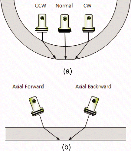
Used in this experiment is an array-type ultrasonic transducer consisting of one 0° normal transducer to check thickness change and wear of steam generator tubes, two 45° shear wave transducers for flaw detection in the axial direction, and two 45° shear wave transducers for flaw detection in the circumferential direction. Beam orientation and array of each transducer is shown in .
2.2. Ultrasonic modeling
Each ultrasonic beam to be arrayed inside the array-type ultrasonic transducer body, which will be inserted into steam generator tubes, should be designed so that they are focused on half way between the inner and outer diameters in order to enhance the transducer's ability to detect flaws occurring on the steam generator tube. High ultrasonic frequency must be applied in order to raise sensitivity for micro-cracks. Also, because ultrasonic transducer to be used in experiments is inserted inside steam generator tubes, it is necessary to analyze ultrasonic beam's propagation characteristics that may occur in a curvature shape. Therefore, a modeling for ultrasonic sound field is necessary to determine various characteristics of such ultrasonic transducers and to evaluate propagation characteristics of ultrasonic beams.
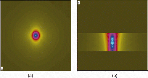
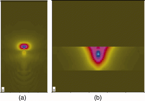
Ultrasonic field was calculated by using three-dimensional modeling in consideration of the actual shape of steam generator tubes. The modeling condition of the tube inside is water filled and the outside condition of tube is air. The Kirchhoff approximate solution was applied to the modeling, and the shear wave speed of the steam generator tube upon modeling was 3020 m/s. In addition, it was assumed that inside the tube was in water condition and outside the tube was in air condition. shows the results of modeling using a normal 0° transducer. As shown in the modeling results in , beam focus of the ultrasonic beam generated from the transducer with 15 MHz frequency was realized in the middle of inner and outer diameters of the tube.
Figure 2. The modeling result of normal beam sound field focused at middle of tube thickness. (a) C-scan image. (b) B-scan image.
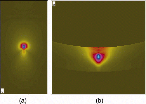
is the modeling result of the CW (clock wise) and CCW (counter-clock wise) transducer which was designed to detect flaws in the axial direction. As shown in the outcomes of C-scan and B-scan, ultrasonic beam was focused in the middle of the tube.
Figure 3. The modeling result of CCW and CW beam sound field focused at middle of tube thickness. (a) C-scan image. (b) B-scan image.
is the modeling result of a beam moving 45° forward and backward to detect flaws in the circumferential direction.
Figure 4. The modeling result of backward and forward beam sound field focused at middle of thickness. (a) C-scan image. (b) B-scan image.
As can be seen from the modeling result, each ultrasonic beam was focused in the middle of the tube thickness. The distance between the transducer and the specimen's inner diameter, as well as the shape of focus lens of the ultrasonic transducer was determined based on the modeling result.
2.3. Ultrasonic transducer assembly design
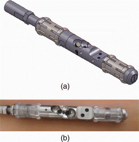
Using the modeling result, an array-type ultrasonic transducer having five transducers arrayed in a cylindrical body with 16 mm diameter was manufactured, which was to be inserted inside the steam generator tube. shows the shape of the array-type ultrasonic transducer designed based on the modeling result and the manufactured transducer.
Figure 5. Ultrasonic transducer for steam generator tube inspection designed based on the modeling result. (a) Modeling result. (b) Manufactured multi-array ultrasonic assembly.
outlines ultrasonic characteristics of each ultrasonic transducer designed to be arrayed.
Table 1. Ultrasonic characteristic measurement of each element (at 6 dB).
3. Specimen and experimental method
3.1. Specimen
For this study, an experiment was performed on steam generator tubes at Uljin Nuclear Power Plant Units 1 and 2, which are known to experience PWSCC and ODSCC flaws. The steam generator tubes at the Uljin Nuclear Power Plant Units 1 and 2 are Framatom-type nuclear reactors whose outer diameter is 22.22 mm and are 1.27 mm thick with relatively larger diameter than Westinghouse or CE reactor steam generator tubes. The tube specifications are shown in .
Table 2. Dimensional specification of steam generator tube specimen.
For this study, a tube specimen with fabricated electric discharge machining (EDM) notch was manufactured in order to perform an experiment to detect flaws. To simulate flaws with various orientations, flaws in the axial and circumferential directions were fabricated at various depths. shows specifications and shape of the notch specimen devised for this experiment.
Figure 6. Test tube drawing for the steam generator ultrasonic testing experiment with artificial flaws (unit : mm).
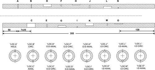
and show detailed dimension including location and orientation of each flaw.
Table 3. Detail dimensions of EDM flaws embedded in steam generator tube.
3.2. Composition of the experimental apparatus
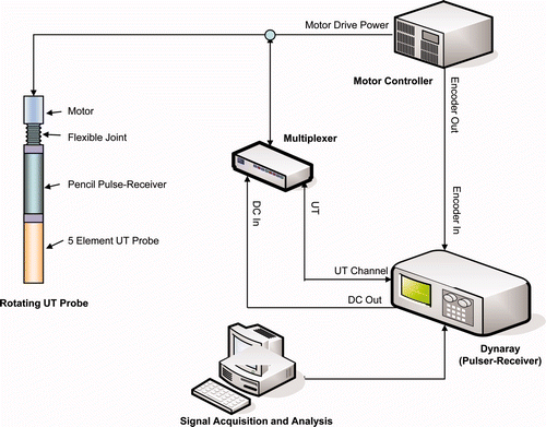
The steam generator tube testing system can be largely divided into two parts, an ultrasonic system and a vertical work bench. The schematic diagram of an ultrasonic system is shown in .
ZETEC's Dynaray was used for the ultrasonic system's pulse-receiver, and a multiplex was installed between the pulse-receiver and the transducer so that five transducers can transmit and receive signals through a single cable, thereby minimizing the diameter of the cable to be embedded into the tube. A dual-axial control was used to allow the transducer body to rotate 360° and to move toward the axial direction of the tube.
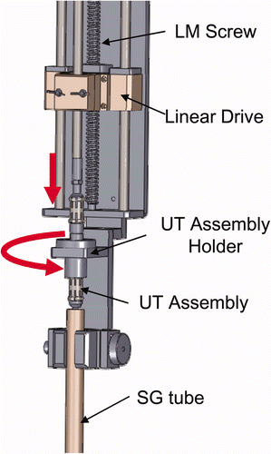
The vertical work bench is devised so that it can fix the steam generator tube and insert and transport the rotating ultrasonic transducer vertically into the tube. Its composition is shown in . The transducer was used to obtain data at 90°/s of rotation speed in the circumferential direction and at 0.125 mm/s of axially travelling speed.
4. Results and discussions
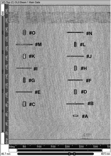
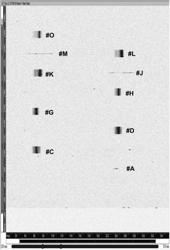
The ultrasonic testing experiment was carried out for detection and quantitative sizing of fabricated flaws in the steam generator tube, and as a result, all of the 15 artificial EDM flaws were detected. represents C-Scan signals of flaws detected from the 0° normal transducer. In , the horizontal direction is the circumferential angle of the tube, whereas the vertical direction represents the axial direction of the tube. As shown in the figure, all 15 flaws were detected, and the geometrical orientation of the flaws could be visibly confirmed. The length and width of the flaws could be measured by using the test results of the 0° transducer.
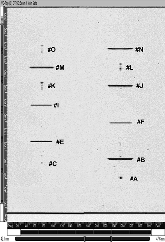
In addition to the 0° normal transducer used in this experiment, all flaws were detected with four 45° shear wave transducers and 0° normal transducers. shows signals as a result of the CW transducer experiment, which was used to detect axial flaws. All axial flaws, i.e. #C, #D, #G, #H, #K, #L, and #O and hole #A with 100% penetration were confirmed. Circumferential flaws having depth greater than 40% of tube thickness and located on tube inside #J and #M were detected but have low amplitude. shows signals detected by the backward transducer whose ultrasonic beam propagates toward the tube's axial direction designed to detect circumferential flaws. As a result of the experiment, all the circumferential flaws #B, #E, #F, #I, #J, #M, and #N were detected. Axial flaws having depth greater than 20% tube thickness and located on tube inside #K, #L, and #O were found. Also, the deepest depth flaw #C located on tube outside is detected.
The length sizing of artificial flaws of the experimental tube was performed, and from the highest amplitude of the flaw to the point where the signal went down to the level of 6 dB was evaluated as the length and width of the flaw, and the tip-diffraction technique using diffracted ultrasonic signals at the top of the flaw was employed as the basic depth evaluation technique. shows sizing results of ultrasonic signals for all EDM notches used in the experiment.
Table 4. Sizing results of detected flaws.
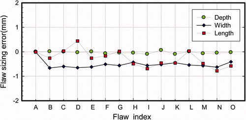
is a graph showing the difference between the length, width, and depth of the notches measured in this experiment and the actual size of the flaws. The horizontal axis is for flaw numbers whereas the vertical axis denotes the error between actual size and the size measured in this experiment. As shown in the graph, the notch's width had the greatest error and the length had a smaller error compared to the width, and the depth had the most accurate result. Length measurement result shows that the biggest error is 0.78 mm, and root mean square error (RMSE) for the measured length of all the flaws was calculated to be 0.42 mm.
Figure 12. Comparison of measured flaw size errors based on flaw length, width and depth for each flaws.
Root mean square error was calculated by using the equation below:
Here, mi = length or depth of the flaw measured in the experiment; ti = length or depth of the actual flaw; n = the number of measured flaws.
Root mean square error of the measurement result for the flaw's width was 0.66 mm. It was analyzed that, although minimization of the ultrasonic beam's focus can be attempted by using a focused ultrasonic transducer, the 0.12 mm EDM notch width was relatively over-evaluated due to the notch's relatively small width as well as overlapping of the ultrasonic beam at both corners, which are the starting points of the notch width. The RMSE value for the depth of evaluated flaw has the smallest error, 0.05 mm, and it was confirmed that the results measured with the tip-diffraction method was quite accurate.
5. Conclusions
In order to measure various flaws occurring at steam generator tubes at a nuclear power plant accurately and quantitatively, an array-type ultrasonic transducer with orientation was designed. From the experiment, the following conclusions could be drawn:
| 1. | An ultrasonic transducer for inspection of steam generator tubes at nuclear power plants was designed through ultrasonic modeling, and an array-type ultrasonic transducer was manufactured based on the modeling results. | ||||
| 2. | By using the manufactured ultrasonic transducer, various types of artificial flaws fabricated inside and outside of steam generator tubes could be detected. | ||||
| 3. | It was possible to detect all fabricated flaws at the inner and outer diameters, and length measurement for all detected flaws was performed with RMS error of 0.42 mm. | ||||
| 4. | Flaws having depth from 20% of the steam generator tube thickness to 100% penetration holes were measured and accurate results with RMS error of 0.05 mm could be obtained. | ||||
| 5. | Consequently, the size of artificial flaws could be measured very accurately by using an array-type ultrasonic transducer in steam generator tubes of nuclear power plants. Thus, this inspection technique, once applied to nuclear power plants, is expected to enhance reliability of steam generator inspection. | ||||
Additional information
Notes on contributors
Byungsik Yoon
†Present address: 1312 Gil, 70. Yuseongdaero Yuseong-gu, Daejeon 305–343, KoreaReferences
- Choi , M.S and Hur , D.H. 2002 . Signal characteristics of eddy current test for intergranular attack of steam generator tubes . J. Korean Soc Nondestruct. Test , 22 : 198 – 199 .
- Choi , M.S. and Hur , D.H. 2001 . Evaluation of eddy current signals from the inner wall axial cracks of steam generator tubes . J. Korean Soc Nondestruct. Test , 21 : 501 – 509 .
- Behravesh , M. and Henry , G. 2002 . Pressurized Water Reactor Steam Generator Examination Guidelines, Revision 6 Charlotte, NC, USA TR-1003138, EPRI NDE Center,
- Gay , L. and Bourgogne , R. Steam Generator Tubes: Crack Sizing by Ultrasonic Inspection Using a Rotating Multi-Transducers Probe . Proceedings of the 7th European Conference on Non-Destructive Testing . May 26–29 . pp. 26 – 29 . Copenhagen, Denmark
- Kenefick , S. and Henry , G. 1999 . Field Implementation of Ultrasonic Crack Tip Diffraction Sizing Techniques in Steam Generator Tubing at Comanche Peak Steam Station, TE-114508, pp 1 – 2 . Charlotte, NC, USA EPRI NDE Center
- Kenefick , S. Recent Applications of Ultrasonic Examination of Steam Generator Tubes . 2nd International Conference on NDE in Relation to Structural Integrity for Nuclear and Pressurized Components . May 24–26 . pp. 3 – 5 . New Orleans, Louisiana, USA
- Kenefick , S. and Henry , G. 1999 . Phased Array Ultrasonic Inspection of Steam Generator Charlotte, NC, USA TE-114394, EPRI NDE Center
