Abstract
A design concept for a small nuclear reactor for neutron transmutation doping silicon (NTD-Si) using a Pressurized Water Reactor (PWR) full-length fuel assembly was proposed in our previous work. The excess reactivity was suppressed by a combination of Gd2O3 and soluble boron, which results in a flatter flux profile over the core than with control rod insertion; however, the soluble boron system for reactivity control is quite complex and expensive. The removal of this system would make the design much simpler. In the current work, the removal of soluble boron is considered. Criticality, neutron transportation and core burn-up calculations were performed using the MVP/GMVP II code and MVP-BURN code. The calculation results show that the insertion of control rods in five of the nine assemblies is enough to suppress reactivity. The thermal hydraulic analysis showed that heat removal from the core was possible under 1 atm operating pressure. Silicon ingots up to 30 cm in diameter could be irradiated with sufficient uniformity in the irradiation channels.
1. Introduction
The use of electric vehicles, such as hybrid cars and electric trains is increasing rapidly. Each such vehicle requires a considerable amount of power semiconductor devices, suggesting an ever-growing demand for such devices in the near future. Thus, the mass production of semiconductor materials is becoming an important issue for many manufacturers.
There are many methods to produce silicon (Si)-based semiconductor materials and the most promising method to produce highly uniform doped Si semiconductor is neutron transmutation doping (NTD). The NTD-Si method is based on a nuclear reaction in which a thermal neutron is captured by the naturally occurring stable isotope 30Si to form the unstable isotope 31Si; this unstable isotope decays by the emission of a 1.471 MeV β− with a half-life of 2.62 h to the stable isotope 31P [Citation1].
Natural Si has three stable isotopes: 28Si (92.3%), 29Si (4.7%), and 30Si (3.1%). These stable isotopes are homogenously mixed in natural Si crystal. The principle of the NTD-Si is that conversion of a small amount of natural stable isotope 30Si into the stable natural isotope 31P by nuclear reaction; uniformly doped Si crystal can therefore be expected after irradiation.
One of the important challenges in this method is how to achieve uniform doping within the Si ingot both in the radial and axial directions. Thermal neutron flux distribution becomes inhomogeneous when a long ingot with large diameter is irradiated. Simple solutions to reduce radial and axial inhomogeneity are rotation of the ingot and constant movement along the axial direction during irradiation.
It was confirmed that almost 1000 tons of NTD-Si will be needed in 2030 to meet the demand. At present, the worldwide capacity of the NTD-Si facilities is estimated to be 150∼180 tons per annum [Citation2]. This capacity cannot be increased drastically because most research reactors with NTD facilities were constructed many years ago and they have little potential for expansion; in addition, the number of research reactors to be constructed in the future is few. Another important issue is that the present research reactors are not NTD-dedicated facilities, and thus a stable and adequate supply is not expected. As such, a new doping facility with a large irradiation capacity for NTD-Si may need to be constructed to ensure an adequate supply of NTD-Si.
A design concept for a small nuclear reactor for NTD-Si using a PWR full-length fuel assembly was proposed in the previous work [Citation3]. The conventional PWR full-length fuel assembly was used to assure the stable and reliable supply of fuel because this small reactor was intended for industrial use only, not for research. The NTD-Si process is usually performed in the existing research reactors, and they use plate-type fuels. The fuel plates are required to be replaced by new ones very often due to the rapid depletion. The number of manufacturers for plate-type fuel is few (limited), and delay in the supply of fuel can be expected. However, there are several manufacturers for PWR-type fuel (pin type). The stable and reliable supply can be expected even if the fuel specifications is little different from the commercial available PWR fuel.
Criticality, core burn-up and neutron transport calculations were performed, and the results showed that the proposed reactor could be critical over 18 years and the excess reactivity was suppressed by a combination of Gd2O3 and soluble boron. Preliminary thermal hydraulic analyses also were performed, and it was confirmed that heat removal from the core was possibly under 1 atm operating pressure. Silicon ingots up to 30 cm in diameter could be irradiated in the reactor irradiation channel and a uniform irradiation condition was achieved for large-diameter ingots. The reactor semiconductor production rate was estimated depending on target resistivity and the estimated rate was 115.5 tons/year for 50 Ω · cm target resistivity.
The soluble boron system for reactivity control is a complex and expensive system. The elimination of soluble boron gives capital and operational savings, and this is the main advantage of the soluble boron free concept. In addition, a negative moderator temperature coefficient is assured for a poison-free moderator. Also, the operational and hardware problems related to soluble boron system can be eliminated.
The purpose of this study was to simplify the previous design concept by eliminating soluble boron. Instead of soluble boron, control rods were used. There are many options for the type of absorption material, and B4C was chosen. Control rod insertion from the top of the core results in the deformation of the neutron flux along the axial direction. It changes the power density distribution in the core and thermal neutron flux in the reflector region; furthermore, it can change the reactor semiconductor production rate.
2. Reactor design
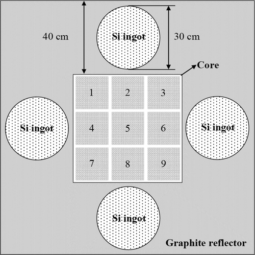
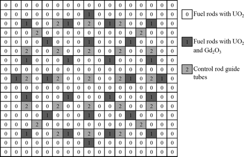
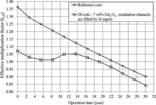
In the current work, the design of the reactor was almost same as that in the previous work; the only difference was the elimination of the soluble boron system. The core size was 64.26 cm × 64.26 cm × 400 cm, and the core contained only 9 (3 × 3) PWR fuel assemblies, numbered 1–9 starting from the top left corner for the convenience of determining the position of the control rods in each assembly (). Enrichment of the fuel was 4 wt%. The coolant and moderator were light water. A 40-cm-thick graphite reflector was placed around the core, and 40-cm-thick water reflectors were placed at the top and bottom of the core. Burnable poison Gd2O3 and control rods were used to suppress excess reactivity. All assemblies were the same, each containing 28 fuel rods with 7.0 wt%-Gd2O3, which was determined as an optimized configuration in the previous work (). The changes in k eff for cases of the reference core, defined as containing no control rods, burnable poison, or soluble boron, but only fuel assemblies and the core with burnable poison (optimized configuration) are shown in . The excess reactivity was greatly suppressed by burnable poison; but excess reactivity still remained, and needed to be suppressed by the insertion of control rods. There are two peaks in the change in k eff, which indicates that the control rods should be inserted at the start of the operation, and then withdrawn to certain level, and then inserted again.
The reactor power was set to 15 MWth, the same as in the previous work, and the operating pressure was 1 atm. There are four irradiation channels in the reflector region and Si ingots up to 30 cm in diameter can be irradiated.
3. Burn-up analyses in reactivity compensation by control rods
There are nine assemblies in the core, and all assemblies have control rod guide tubes. The assemblies are numbered as 1–9 as shown in . The main requirement for use of the control rods is to not reduce the neutron flux too drastically in the reflector region where the Si ingots are to be inserted. To achieve this requirement, control rods need to be inserted in as few assemblies as possible, and not in the assemblies close to the irradiation channels. Thus, assemblies 2, 4, 6, and 8 were excluded from control rod insertion because they are the assemblies closest to the irradiation channels, although emergency control rods can be inserted there. The control rods for reactivity control were only inserted in the remaining assemblies. The insertion of the control rods results in the deformation of the neutron flux along the axial direction. Therefore, higher local power peaking is expected, and the water coolant temperature can rise drastically; boiling could even occur locally since the reactor operating pressure is 1 atm. The power peaking was limited by the melting point of UO2 fuel and Zircalloy-4 cladding, and the coolant temperature which should be lower than 100°C. The coolant density coefficient should be negative. The boron-free coolant can assure the negative coefficient.
Criticality and burn-up analyses were performed to determine the positions of the control rods using the continuous energy Monte Carlo code MVP/GMVP II [Citation4] with the JENDL-4.0 data library [Citation5]. The core burn-up calculation was carried out by auxiliary code MVP-BURN [Citation6]. The MVP-BURN code enables the burn-up calculation using both the continuous-energy Monte Carlo code MVP and the auxiliary code BURN, which calculates the buildup and decay of nuclides in irradiated materials. The execution of MVP is possible if the geometry and material composition are given. As a result of the MVP execution, microscopic reaction rates of every nuclide were calculated in every spatial region. On the other hand, depletion calculation is possible if the microscopic reaction rates are given. The BURN code has the function of depletion calculation, file management, and interface with MVP. Alternate executions of MVP and BURN constitute a whole burn-calculation.
In Okumura et al. [Citation6], the MVP-BURN was applied to the analysis of a post irradiation experiment together with SRAC95 and SWAT codes. It was confirmed that the effect of statistical errors of MVP-BURN was sufficiently small, and could give a reference solution for other codes. The result of the three codes with JENDL-3.2 agreed with the measured values within an error of 10% for most nuclides; however, large underestimation by about 20% was observed for 238Pu, 242mAm, and 244Cm. It was suspected that it was a common problem for nuclear data files which were existed in that time.
Benchmark calculations were also performed with continuous-energy Monte Carlo code and with the deterministic procedure with JENDL-4.0 nuclear data library, and the calculations with JENDL-4.0 were reproduced the experimental values of criticalities of uranium-fueled and MOX-fueled light-water-moderated systems within about 0.5% Δk/kk′ differences [Citation7].
The MVP-BURN calculations for same core configuration and burn-up time step with different history numbers, such as 1, 6.5, 13, 26, and 52 million for each burn-up step, were performed to check the effect by the history numbers. The difference of k eff between two calculations with different history numbers became very small (within 0.07%) after the history number reached 13 million or more. The history numbers of 13 million was chosen to minimize the computation time.
The MVP-BURN calculations for the same core configuration and history numbers with different burn-up time step, such as 2000, 1000, 500, and 320 days for each burn-up step, were performed to check the effect by the time step. The time step was basically limited by the computational time, and 1000 days for each burn-up step was chosen. The difference of k eff between two calculations with different burn-up time step was within about 7% during the burn-up calculation after the time step was reduced to 1000 days or less.
The similar calculations were also performed changing the size of the tally region. If the coarse tally regions were defined, the reaction rate error decreased, but the local power peaking could not be determined clearly. If the very fine tally regions were defined, the reaction rate error increased drastically which could lead even more statistical error in further burn-up steps. Considering these effects, non-uniform tally regions were selected to be as an optimum definition, and the every section of the fuel pin with burnable poison was tallied separately from the normal fuel pins. A total number of the tally region reached 840.
The burn-up time step was 1000 days and there were 12 steps in one calculation. MVP calculation was carried out at the start point of each burn-up step, and each burn-up step was divided into 20 substeps for the depletion calculation by BURN. The calculation geometry is shown in , and the calculation conditions are shown in . The standard chain model for nuclear calculation (u4cm6fp50bp16T) was used for the burn-up chain model. The number of history for each burn-up step was 13 million.
Table 1. Calculation conditions.
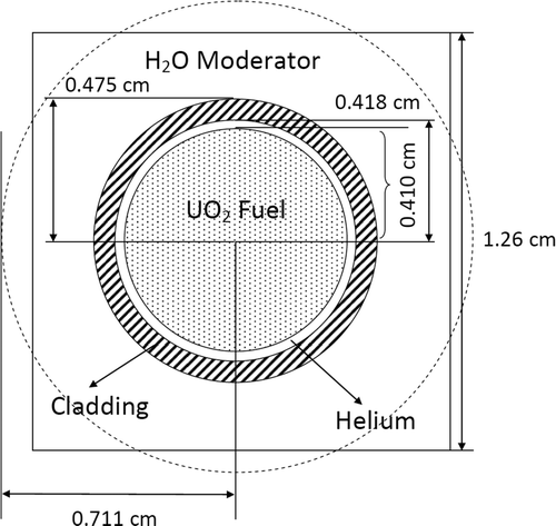
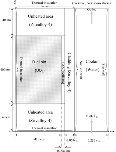
In order to check the fuel, cladding surface, and coolant temperature, preliminary thermal hydraulic analyses for normal operation were performed in each burn-up step. From the burn-up analysis, the location of the power peaking and the axial power density distribution at that location could be obtained for each burn-up step. Based on the obtained local power density distribution, single-channel steady-state preliminary thermal hydraulic analysis was performed using COMSOL Multiphysics [Citation8] which is a finite-element analysis, solver, and simulation software. An axial-symmetry (2D, r–z) geometry was used in the analyses. The actual cell was square and it was changed to circle with an equivalent area in order to use a 2D symmetric geometry model (). The calculation geometry and boundary conditions are shown . A 40-cm unheated area was added to both the top and bottom of the channel to obtain fully developed turbulence flow in the channel. The calculation conditions are shown in . The material properties of the coolant, cladding, gap, and unheated area were taken from the COMSOL material library. In the simulation, the solid–fluid interaction in the turbulence flow, the compressible Navier–Stokes equation (k– ϵ turbulence model), and Fourier's law of conduction (convection and conduction model) were used.
Table 2. Calculation conditions.
The control rods were inserted to the assemblies from the top of the core, and their positions were determined as the distance in centimeters from the bottom of the core for each burn-up step. The positions of the control rods in each fuel assembly, numbered 1–9 in , were determined in each burn-up step (). If the position equals zero, that means that the control rods are fully inserted. The control rod in assembly 5 are used only to suppress initial excess reactivity, and the four corner assemblies, numbers 1, 3, 7, and 9, are basically used for reactivity control. Up to burn-up step number 4, the control rods are continuously withdrawn; but they are reinserted at this step because of the complete burn-out of the burnable poison.
Table 3. Control rod positions.
There was enough shutdown margin such that k eff well below critical even with the most reactive control rod, which was the control rod in the number 5 assembly, stuck in the full out position. If the control rod in the assembly 5 was stuck in the full out position, and all remaining control rods were fully inserted, the k eff would become 0.827 or less depending on the time of the control rods insertion (). During the normal operation, the control rods in number 1, 3, 5, 7, and 9 assemblies were used for reactivity control, and the k eff would also become well below the criticality if those control rods were fully inserted.
Table 4. Excess reactivity and shutdown margin.
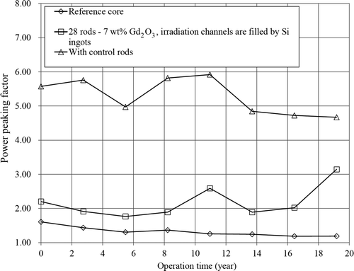
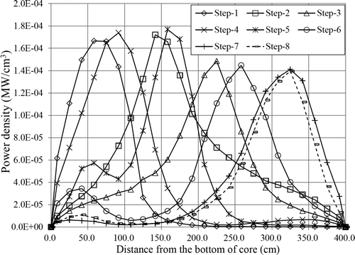
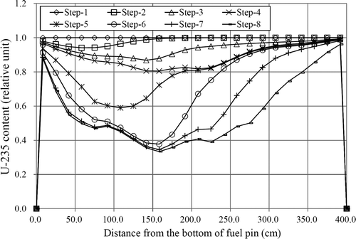
The depletion of the 10B in the local region of control rod was estimated. The estimation result showed that the depletion of the 10B was very small, and there was almost no effect on the position of the control rods, and the control rods were not necessary to be replaced during the reactor operation. In case of control rods in the assembly 5, the total depletion during the reactor operation was 0.65% of initial content, and in cases of four corner assemblies, numbers 1, 3, 7, and 9, total depletion at the end of the reactor operation was 1.7% of initial content. The power peaking factor (PPF), the ratio of maximum to average power density, was determined in each burn-up step, and the results are shown in . The power peaking factors are much higher than the cases of reference core and the core with burnable poison only. The axial power density distributions were determined where the power peaking occurred in each burn-up step (). At burn-up steps 5 and 6, smaller peaks appeared at the bottom of the core, and the peak became smaller in further steps. The local power peaking was shifted between several fuel pins during the burn-up, and the both U-235 content and thermal neutron flux of the pin where the peaking was occurred at the burn-up step 5 are shown in and 9. First, the control rods were inserted deep and withdrawn; then reinserted deep and withdrawn again. Due to the control movement, the top part of the bottom half of the pin was depleted more compared to the other part until burn-up step 5. The control rods were partially inserted from the top, and the thermal neutron flux was much higher at the bottom half of the pin. As a result of the depletion, a smaller peak was appeared at the bottom of the pin in the power density distribution; but the peak is not very high because of the neutron leakage.
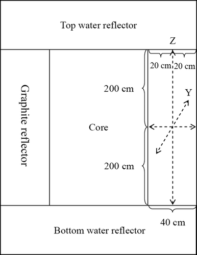
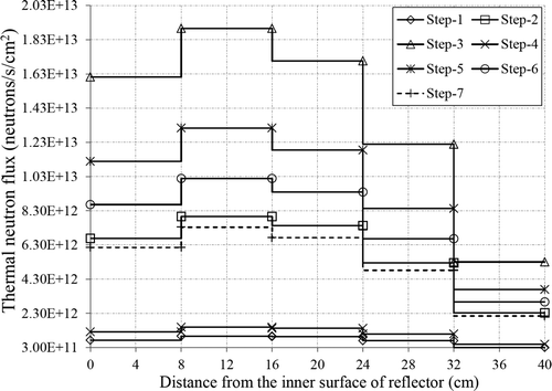
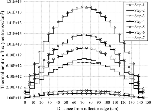
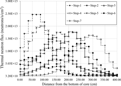
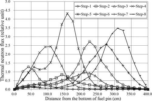
The change of thermal neutron flux in the reflector region due to the control rod insertion was obtained. The location of interest in the reflector region is shown in . The irradiation channel was filled by graphite in order to determine the neutron flux spatial dependence. The Z-axis is the vertical central axis of the irradiation channel. The X-axis and Y-axis are perpendicular to each other, and they are on the horizontal middle plane of the side reflector. The reason for choosing these axes is to check whether the thermal neutron flux is shifted or not in the horizontal direction. If the flux shifts horizontally with the control rod movement, the position of the irradiation channel needs to be changed. The thermal neutron flux distributions along the X, Y, and Z directions in each burn-up step were determined up to burn-up step number 7. At step 8, the reactor becomes subcritical. The results are shown in –13. The shapes of the thermal neutron flux distributions along the X- and Y-axes were not changed due to the control rod insertion, but the absolute values were changed. The positions of the irradiation channels did not need to be changed. However, the shape of the thermal neutron flux distribution along the Z-axis was changed depending on the control rod position.
Figure 9. Thermal neutron flux of fuel pin where the local power peaking was occurred at burn-up step 5.
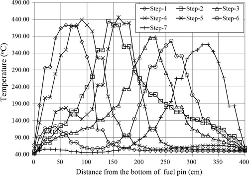
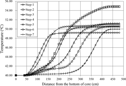
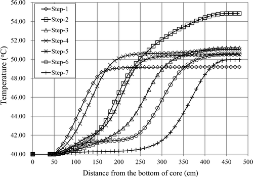
The fuel centerline temperature profile, cladding outer surface temperature profile, and the coolant bulk temperature profile for each burn-up step are shown in –16. The maximum fuel temperature was below 450°C all the time which was well below the melting point of UO2 and Zircalloy-4. It also confirms that the cladding outer surface and the coolant temperature do not exceed 56°C during the reactor operation even if much higher local power peaking occurs due to the insertion of the control rods. The peaks in each burn-up step are very high, but they are narrow peaks, and the average power density is still low compared to the conventional PWR.
4. Uniformity of doping
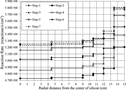
The thermal neutron flux distribution in the reflector region has a large gradient in both the radial and axial directions. To overcome these difficulties, the ingot rotates on its axis and moves with constant speed along the axial direction during the irradiation. But the neutron absorption reaction rate is much higher at the circumference than at the center for the large-diameter Si ingot. The ratio of the absorption reaction rate at the circumference to that at the center, called the O/C ratio, needs to be below 1.1, which is set by considering the in-plane electrical resistivity within ±5% error provided by semiconductor makers in some countries [Citation9]. From the O/C ratio, the radial reaction rate variation (δ) can be calculated using a simple formula (1), and the reaction rate variation needs to be within 9.52%.
RR max and RR min are, respectively, the maximum and minimum 30Si neutron absorption reaction rates in the radial direction. However, the simple rotation of the ingot and constant movement along the axial direction during the irradiation is not enough to achieve this requirement, and an additional procedure is needed. To achieve this goal, graphite spacers, with a height of 25 cm, were placed between the ingots to allow neutron current into both the top and bottom of the ingots in addition to the rotation of the ingot and constant movement along the axial direction during the irradiation, and the ingot height was limited by 20 cm in the previous work. The same idea was used in the current work.
In addition, it is desirable to have as thermalized spectrum as possible in order to reduce the irradiation damage in the crystal lattice by fast neutrons. The ratio of thermal to fast flux for a given location is an important factor to evaluate the neutron spectrum. The fast flux is considered to be the part of spectrum above 0.18 MeV. The general recommendations for new NTD-Si facilities were published in the IAEA technical document [Citation10]. They state that the thermal-to-fast flux ratio should be about 7:1, and the temperature at the irradiation position should be lower than 180°C.
A neutron transport calculation was performed in the reflector region by the continuous energy Monte Carlo code MVP/GMVP II with the JENDL-4.0 data library to determine the 30Si neutron absorption reaction rates and neutron flux in the ingots. The ingots were divided into six radial meshes; it was not, however, divided along the axial direction, assuming that the ingots move along the axial direction with constant speed in the irradiation channel. Each layer of ingots was tallied independently for each ingot to determine the neutron absorption reaction rate. For the doping calculation, the number of history for each burn-up step was increased to 300 million to obtain the thermal neutron flux and 30Si neutron absorption reaction rate with less than 1% of statistical error.
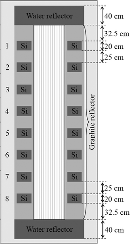
Up to eight ingots, 20 cm in height, 30 cm in diameter, can be placed in a single irradiation channel (). The 30Si neutron absorption reaction rates at positions 1–8 were determined for each burn-up step. The calculation results show that the reaction rate variations are within the limit for all positions, but the absolute value of the reaction rate changes with the control rod movement and burn-up step. In order to show these changes, the average 30Si neutron absorption reaction rate was determined for each burn-up step assuming that the ingots pass through an irradiation channel once (). The reaction rate changes with control rod movement and burn-up steps, but the change of the absolute value is not that great, and the gradients are almost the same. Also, the results show that the thermal-to-fast flux ratio changes with the position of the Si ingot and burn-up step, but the ratio is always better than that recommended value. If the Si ingot passes through the irradiation channel once, the ingot will experience a thermal-to-fast flux ratio of about 7.1:1 during reactor operation.
5. Estimation of the semiconductor production rate
The target resistivity of the doped Si ingot depends on the number of 31P nuclei introduced by NTD-Si. A specific period of irradiation time is required to create that number of phosphorus nuclei, and the required time depends on the reaction rate in the Si ingot and the ingot movement speed along the axial direction.
If the initial ingot does not have any impurities, the initial resistivity of the ingots is infinite, and the target resistivity of the ingots depends only on the number of phosphorus nuclei that are created in the Si by irradiation. The relationship between target resistivity and the number of phosphorus nuclei after irradiation was determined by an empirical formula, obtained by JAERI [Citation11], as:
The approximate semiconductor production rate of the reactor was estimated assuming that Si ingots went through the irradiation channel once. The total number of phosphorus nuclei after irradiation can be determined if the target resistivity is set. In order to estimate the approximate production rate, the irradiation channel was divided into eight identical vertical regions (leaving some unused spaces at the top and bottom), with each region containing one ingot located exactly at the middle of the region (). It is assumed that the neutron absorption reaction rate in each vertical region is the same as the reaction rate in the contained ingot.
The average neutron absorption reaction rates at positions 1–8 were obtained. If the ingot goes through the irradiation channel once with constant speed, the amount of time that the ingot stays at each vertical region can be estimated, as can the total number of reactions in each vertical region. The required speed was determined by comparing the total number of phosphorus nuclei after irradiation, which was set by the target resistivity and the sum of the total reactions in all vertical regions. In the calculation, it was assumed that ingots are loaded continuously into all four channels, and that the reactor is in 24-h operation for eight months per year, considering regular maintenance.
Since the 30Si neutron absorption reaction rates in ingots change with control rod movement and burn-up steps, the speed of the ingot is different in each burn-up step. The speed (V) and the semiconductor production rate were estimated for each burn-up step depending on the target resistivity, and the results are shown in .
Table 5. Semiconductor production rate at each burn-up step.
In case of the required 50 Ω · cm target resistivity, the speed of the ingot varies between 6.59 and 8.29 cm/h, and the production rate varies between 111.11 and 139.75 tons/year. A reduction in the reactor semiconductor production rate was expected due to the additional neutron absorption by the control rod insertion, and there would not be much advantage for elimination of soluble boron if the reduction was too much. However, it was confirmed that almost no reduction was in the production rate. At the time step 2, the production rate was decreased below the previous work result, but the rate was increased in the further time steps. The average semiconductor production rate for the whole reactor operation period is 123.73 tons/year which is slightly higher than outcome in the previous work. The reason for this slight increase is unclear, and it depends on many parameters, such as depletion of the burnable poison, and position and movement of the control rods.
6. Conclusion
The design of a small nuclear reactor for large-diameter NTD-Si can be simplified by eliminating the soluble boron system. Instead of the soluble boron, the excess reactivity can be managed by control rods. Excess reactivity was suppressed mainly by the control rods in the four corner assemblies, but the control rods in the central assembly were needed at the beginning of the reactor operation. A higher power peaking was observed due to the control rods insertion; however, heat removal from the core was possible under 1 atm operating pressure.
Large-diameter ingots 20 cm in height could be irradiated in the reactor irradiation channel with sufficient uniformity and the estimated production rate varied between 111.11 and 139.75 tons/year for 50 Ω · cm target resistivity depending on the control rod positions.
References
- Tanenbaum , M. and Mills , A.D. 1961 . Preparation of uniform resistivity n-type silicon by nuclear transmutation . J. Electrochem. Soc , 108 : 171 – 176 .
- Kim , M.S. , Park , S.J. and Lim , I.C. 2007 . Estimation of Future Demand for Neutron-Transmutation-Doped Silicon Caused by Development of Hybrid Electric Vehicle and Its Supply from Research Reactors , Daejeon , , South Korea : Korea Atomic Energy Research Institute . Available at http://www.kaeri.re.kr/
- Munkhbat , B. and Obara , T. 2012 . Design concept of a small nuclear reactor for large-diameter NTD-Si using a conventional PWR full-length fuel assembly . J. Nucl. Sci. Technol , 49 : 535 – 543 .
- Nagaya , Y. , Okumura , K. , Mori , T. and Nakagawa , M. 2005 . MVP/GMVP II: General Purpose Monte Carlo Codes for Neutron and Photon Transport Calculations based on Continuous Energy and Multigroup Methods , Tokai , , Japan : Japan Atomic Energy Research Institute . JAERI–1348
- Shibata , K. , Iwamoto , O. , Nakagawa , T. , Iwamoto , N. , Ichihara , A. , Kunieda , S. , Chiba , S. , Furutaka , K. , Otuka , N. , Ohsawa , T. , Murata , T. , Matsunobu , H. , Zukeran , A. , Kamada , S. and Katakura , J. 2011 . JENDL-4.0: A new library for nuclear science and engineering . J. Nucl. Sci. Technol , 48 : 1 – 30 .
- Okumura , K. , Mori , T. , Nakagawa , M. and Kaneko , K. 2000 . Validation of a continuous-energy Monte Carlo burn-up code MVP-BURN and its application to analysis of post irradiation experiment . J. Nucl. Sci. Technol , 37 : 128 – 138 .
- Chiba , G. , Okumura , K. , Sugino , K. , Nagaya , Y. , Yokoyama , K. , Kugo , T. , Ishikawa , M. and Okajima , S. 2012 . JENDL-4.0 benchmarking for fission reactor applications . J. Nucl. Sci. Technol , 48 : 172 – 187 .
- COMSOL-3.4 . Multiphysics Modeling and Engineering Simulation Software, COMSOL AB, 1994–2007 Available at http://www.comsol.com/
- Yagi , M. , Watanabe , M. , Ohyama , K. , Yamamoto , K. , Komeda , M. , Kashima , Y. and Yamashita , K. 2009 . Conceptual design of experimental equipment for large-diameter NTD-Si . Appl. Radiat. Isot , 67 : 1225 – 1229 .
- IAEA . 1988 . Silicon Transmutation Doping Techniques and Practices , Vienna : International Atomic Energy Agency (IAEA) . IAEA-TECDOC-456
- Horiguchi , Y. and Umei , H. 1986 . Silicon Doping by Neutron Irradiation , Tokai , , Japan : Japan Atomic Energy Research Institute . JAERI-M 86-002 [in Japanese]
