Abstract
A simple evaluation method for the analysis of thermal-hydraulic transients in reactor pressure vessel (RPV) and primary containment vessel (PCV) is proposed to support understanding the accident behaviors of the Fukushima Dai-ichi nuclear power plant (NPP). Since most of the measurements of the plants were unavailable especially in the early stage of the accident, and the accessibility to the plants had been limited by radiation, analytical investigation for the plant was required to understand the plant conditions such as the magnitude of the damages. In order to provide easy-to-use technical tools to support the analytical investigation, we developed a simplified analysis code, named “HOTCB”, based on total mass and heat balances in a lamped parameter system. The HOTCB code has capabilities to treat two-phase fluid including water, steam, and non-condensable gas in a wide range of temperatures up to highly superheated conditions, and to consider heat structures, i.e. heat capacities and heat transfer to the fluid. The code was provided to Tokyo Electric Power Company (TEPCO) and was practically used for the analysis on the accident. This paper provides the details of the code and simulations of Unit 1 and Unit 2 reactors of Fukushima Dai-ichi nuclear power plant (NPP) as examples to show the usefulness of the code.
1. Introduction
In the accident of the Fukushima Dai-ichi nuclear power plant (NPP) of Tokyo Electric Power Company (TEPCO), the loss of core cooling capability resulted from the station blackout (SBO) which occurred at Units 1 through 4 due to the attack of the tsunami, together with the loss of ultimate heat sink (LUHS). Although the alternative water injection to the reactor pressure vessel (RPV) using fire pumps was carried out as an accident management measure, the reactor cores in the Units 1, 2, and 3 reactors were severely damaged and a large amount of radioactive materials were released to the environment.
In addition, the measurements became unavailable to use due to the loss of direct-current power source, so that we encountered engineering difficulties in understanding the damages and the associated thermal-hydraulic conditions in the early stage of the accident. Because of the insufficiencies of the measurements, it was crucial to analyze the plant conditions using available information to the maximum extent possible. For such analyses, furthermore, nimble footwork and high robustness are required, even though it might be a rough estimation, to timely provide appropriate technical information. Detailed analysis using sophisticated system analysis codes, such as RELAP5 [Citation1] and TRAC [Citation2], is not suitable in this view point because plant parameters necessary for the analysis are limited and a lot of time and labor are required for the preparation of input data.
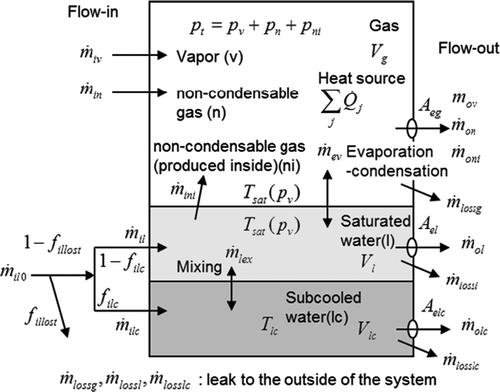
We have, therefore, created a simplified analysis code based on the evaluation of the mass and heat balances with the concept shown in . Some results using the first version of the code designated as “CVBAL” have been already published [Citation3]. This version was unable to take into account the heat transfer between heat structures and fluids, and also to superheated state of vapor. The model of heat structure exposed to superheated vapor is crucially important for evaluating core damage and thermal-hydraulic responses during plant transients including a severe accident. Thus, we have modified CVBAL to improve its analytical capability for a severe situation. The present paper describes models and numerical scheme of the improved CVBAL code designated as “HOTCB” code.
Figure 1. A mass and heat balance model for the evaluation of pressures and temperatures based on the situation inside the vessel and the inlet/outlet conditions.
In this paper, the analytical models for the HOTCB code are presented in detail with some analysis results focusing several characteristic behaviors observed during the accident. As shown in those analyses, many sensitivity calculations are required to identify important parameters and evaluate their possible ranges. In order to limit the length of the paper within the acceptable range, we will focus on the presentation of the usefulness of the code to estimate the accident conditions from the observed data. Therefore, analyses requiring thorough sensitivity calculations such as the pursuance of the most probable scenario are not discussed in this paper.
2. Analytical model
As shown in , the model consists of vessel including two-phase fluid with non-condensable gases and heat structures simulating core, RPV internal structures and vessel wall. The models of vessel and heat structures are named “Hot Can” and “Hot Body”, respectively, and the combined code is named “HOTCB (Hot Cans and Bodies)”. The code applies conventional numerical scheme for fundamental equations and simplified models with combining existing reliable correlations. Several means are made for high robustness and fast computing on them. The contents of each model are explained in this section.
2.1. Hot Can model
shows the concept of the hot can model that considers mass and heat balances in a vessel with mass input–output (I/O) and heat sources. Symbols used in this figure including attributes of components in the model (k = v,l,lc,n,ni) are summarized in Nomenclature.
The model assumes thermally equilibrium two-phase fluid if water exists in the vessel. The gas phase can include non-condensable gases and the equilibrium temperature is the saturation temperature of water at the steam partial pressure in the gas phase. The model also has an ability to treat superheated vapor if water in the vessel vanished. We consider a subcooled water layer, shown at the bottom in (denoted by subscript “lc”) to handle a part of water in the vessel that is somehow isolated and does not receive heat from heat sources of the other part of the fluid. Its temperature is given externally from input data, although the mass and the energy are included in their conservation equations. Mass exchange between the subcooled water and the saturated water can be given from the input, too. Practically, a tuning of the mass exchange rate of the subcooled water with the saturated part can change the pressure transient, so that we can match the calculation with observed data. When we obtain a good agreement of the calculated and observed pressure transients with given conditions of the subcooled layer, we can interpret that a thermally equivalent phenomenon is included in the vessel. The details of adopted models are described below. The numerical solution method is briefly described in Appendix 1.
2.1.1. Mass balance
The mass conservation equations for component k can be expressed by using variables mentioned in as follows,
2.1.2. Energy balance
The total internal energy, E, and its conservation in the system are expressed as follows.
The first line of the right-hand-side in Equation (9) denotes the work at the inlet and outlet, the second and the third the internal energy of flow-in and -out, and the last term the heat input. The evaporation term and mixing term of subcooled and saturated water
do not appear in Equation (9) because they are cancelled in the total energy equation. The gas flow-in work Wgi
is:
Three ways of handling the inlet condition are provided:
| • | separate flow-in of gas components with given inlet pressure for each; the densities and internal energies are evaluated at given pressures piv, pin, pini and given temperatures Tiv, Tin, Tini , | ||||
| • | separate flow-in with the total pressure inside the vessel pt for all the components, or | ||||
| • | flow-in as a mixture. | ||||
The mixture density is given by the following.
where
The outlet work Wgo is evaluated with an assumption of mixture flow-out.
2.1.3. Equation of state
The state equations of component k: density, specific internal energy, and equilibrium gas temperature become
The total pressure and total density of the gas phase should satisfy,
The water-vapor state is calculated by a fast running wide range steam table program, based on a table of values calculated by the JSME steam table equation [Citation4]. The ideal gas equation was used for non-condensable gases (e.g. N2, H2) with the zero point of the energy placed at 273 K.
2.1.4. Exit condition
It is assumed that each of liquid and gas flow out separately at the exit holes. The flow rate is expressed by the following, with the holes' area, the density and the velocity. The velocities of gas components are assumed common (uniform mixture).
The Bernoulli's law for incompressible fluids is used for the liquid phase.
The specific heat ratio of the gas mixture, γ, is calculated by the averaged specific heat of gas component. Flow rates of each gas component become
and
. Note that u is not the actual velocity at the hole exit, but a hypothetical velocity defined by (mass flow rate) / (hole area × up-stream density), and common for all the gas components (uniform mixture assumption).
The explicit evaluation of the flow-out rate of the gas can make the decreasing total pressure going below the outside pressure. In such cases, the flow-out rate is forced to be zero in the next time step. However, this method may cause non-physical oscillation of the pressure when the overshooting of the decreasing pressure is significant. For a remedy for this, a limitation for the velocity u is applied by the following.
The first term in the brackets means the flow-out gas volume corresponding to the maximum possible pressure decreases, the second term means the water evaporation volume corresponding to that pressure decreases. After some test calculations, f lim = 1.5 is taken as default setting. Changing this setting changes the can pressure slightly, but the mass flow-out rate does not change significantly.
2.2. Hot Body model
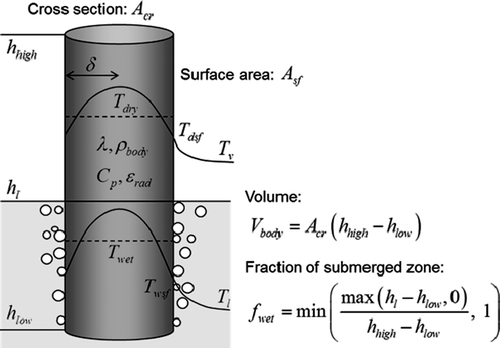
illustrates the model for a hot body with cross-sectional area Acr , heat transfer surface area Asf , top and bottom end elevations hhigh and hlow . Thermo-physical properties (density ρ body , specific heat Cp , thermal conductivity λ and emissivity ϵ rad ) and heat generation rates are considered for the bodies. The surface heat transfer rates to the surrounding fluids are evaluated with empirical correlations by considering the fluid conditions including gas components and water level. The surface temperature is used for the evaluation because sometimes the difference between the surface and inside temperatures becomes large depending on the fluid properties and the solid physical properties.
2.2.1. Evaluation of the surface temperature and the heat flux
Empirical correlation equations for heat transfer generally give non-linear dependence of the surface temperature and heat flux. With the heat transfer coefficient H (a non-linear function of a body's surface temperature; Tsf ), the surface heat flux q′′ is expressed by
Figure 4. Solution method for the surface temperature (Left: when the heat flux is a monotonic function of the wall temperature, Right: when the function is not monotonic (boiling curve). The horizontal axis variable is noted by with asterisk meaning it is parametrically moved).
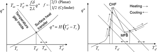
The situation is simple when the heat transfer coefficient is a monotonic function of the surface temperature, e.g. in such cases as convection heat transfer. Boiling heat transfer makes the situation much more complicated: the function q′′(Tsf ) (or H(Tsf )) is highly non-linear. Visualizing the geometric relation of the lines gives a perspective on the cases that should be considered to find correct solutions, including a jump when the boiling transition or quenching takes place. Thus, we have the solution for the surface temperature and the heat flux, which are given by the average temperature inside the body and the surface heat transfer condition. In the program, the intersection in is obtained by the bi-section convergence method.
2.2.2. Energy conservation equations
The energy conservation for the body is expressed as follows. Dry zone (exposed to the gas phase):
The surface temperatures in those equations are replaced with average temperatures by using the geometric relation of the temperature profiles,
Then, the finite difference form of the energy equations lead to a set of simultaneous linear equations for the average temperatures in the dry and wet zones, Tdry, Twet , at the new time step.
When whole the body is in one of the dry or wet zones, only one relevant equation suffices.
2.2.3. Heat transfer correlation equations
The surface heat flux or the heat transfer coefficient is given by considering radiation, natural convection, nucleate boiling and film boiling heat transfer, with a collection of well-known and widely-used existing correlation equations summarized in . The correlations describe well the difference of each heat transfer mode, but the applicability to an arbitrary system is not separately optimized. The radiation heat transfer is considered only between the body and the fluid; heat transfer between multiple bodies is not handled, since modeling of radiation among multiple bodies is considered too complicated for the scope of this work. The heat flux of the radiation is simply added to the heat flux due to the convection. The film temperature (the average for the bulk fluid and the heat transfer surface) is used in evaluating the fluid physical properties for film boiling and gas phase convection, because the temperature difference between the bulk and the surface may be large. Note that the saturation temperature of water for the boiling heat transfer is given at the total pressure of the gas phase, not at the partial pressure of steam.
Table 1. Heat transfer correlation used in the HOTCB code.
The heat transfer surface for gas phase may not be fully effective in some cases such as a rod bundle filled with stagnant gas, with the gas temperature close to that of the rods and the radiation from each rod mostly absorbed by other rods. In such a case, only outer enveloping surface is effective for heat transfer. We put the following factor to the physical surface area Asf to take account of this situation.
2.2.4. Handling of movement and geometry change of the body
Variables for the geometry and position of a body: cross section Acr , surface area Asf , top and bottom end heights hhigh and hlow can be variable in time. There are two methods to give the volume as follows,
| • | Conserve the volume and move the top/bottom ends: give hhigh and hlow by time tables, and give a single constant for Acr ; the volume is calculated at the initialization and kept constant; the cross section Acr is updated during the calculation with the volume kept constant. | ||||
| • | Change the volume (the body emerges/disappears): give Acr, hhigh and hlow by time tables. | ||||
| • | Give the surface area Asf with a single value or by a time table. | ||||
| • | Give the characteristic length ll (=δ) with a single value or by a time table and evaluate the surface area. | ||||
The latter is equivalent to the radius of a circular rod or half the thickness of a flat plate as thermal boundary layer thickness shown in . The surface area Asf is obtained by Asf /Vbody = 2/ll assuming rod bundle geometry. When a body moves from a can to the other, it is treated as disappearance of a body in a can and emergence of one in another. The energy should be conserved.
2.3. Synthesis of Hot Can and Hot Body models
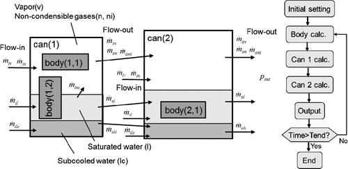
“Hot Can” and “Hot Body” described in Sections 2.1 and 2.2 can be applied for a system with multiple cans or bodies and solved in tandem (explicit coupling) for every time step. The solution for time evolution is stable and fast enough. HOTCB is a program, as illustrated in , to model a system with arbitrary number of cans including arbitrary number of bodies each connected in tandem. Other type of systems can be modeled if the main routine is modified.
3. Examples of the HOTCB Code analysis for the Fukushima Dai-ichi NPP accident
In this section, examples of the HOTCB analysis are presented to show how the code can be used to evaluate boundary conditions from the observed data during the Fukushima Dai-ichi NPP accident. Three topics were selected for this purpose: a rapid primary containment vessel (PCV) pressure increase observed late at night on March 11, and a temporal pressure increase observed around March 23 both for the Unit 1 reactor, and the PCV pressure during the first three days for the Unit 2 reactor.
3.1. Analysis for the Unit 1 reactor
Two characteristic phenomena were focused for the analysis of the Unit 1 reactor. The first phenomenon focused was a rapid increase of the PCV pressure observed within ten hours from the earthquake. The PCV pressure was found to be 0.6 MPa at 1:05 on March 12 (0.39 day after the SBO on the Unit 1 reactor), and further increased to 0.84 MPa at 2:30 (0.45 day). The RPV pressure was almost equalized with the PCV pressure at 2:45 (0.46 day), indicating the occurrence of the damage of the RPV pressure boundary before this time. This rapid pressure increase might have been caused by the vapor generation due to the decay heat release, the generation of hydrogen gas and energy due to the zirconium–water reaction, and so on. Since fresh water injection supposedly started at 5:46 on March 12 (0.59 day), it had no effects on the observed maximum pressure.
The boundary conditions used in the present analyses are summarized in . Since the present analysis focuses on the behavior after the tsunami attack (the calculation started at a time of the SBO), the isolation condenser (IC) is not modeled. Major parameters investigated were thermal stratification in the suppression chamber (SC) pool, zirconium–water reaction rate, leak condition, and water injection rates. The thermal stratification was possible to occur if the elevation of the outlet of the safety relief valve (SRV) line was not at the bottom of the SC liquid pool. That is, the pool water below the outlet might not have contributed to the condensation of the vapor flow through the SRV line. Since the elevation of the outlet was not available in the public domain, the effect was investigated in the sensitivity calculations.
Table 2. Major initial and boundary conditions for analyses of the Unit 1 reactor.
The zirconium–water reaction was modeled by adding the hydrogen gas and energy to the hot can representing the RPV and the hot body in there, respectively, of which conditions were assumed to be excessive compared to those calculated using the severe accident codes [Citation8,Citation9]. To give the excessive reaction rate, it was assumed that all the zirconium in the bundle wall and fuel cladding reacted with steam in 2.4 hours (0.3 to 0.4 day). The purpose of this assumption was to investigate effects of the other parameters by simplifying the effects of the zirconium–water reaction. The decay heat was calculated using the Way–Wigner equation [Citation10] with consideration of the fuel burnup. The water injection rates were based on the data of the injected mass per day and the event records published by TEPCO [Citation11]. Steam was discharged from the RPV to the SC through the SRV line so that the RPV pressure was controlled at the SRV operation pressure of around 7 MPa before the RPV failure. A large leak path was assumed between the RPV and PCV for the pressure equalization. After the assumed core relocation, the fuel geometry changed to a debris geometry with a packing ratio of 0.6 and a shape of 5 cm sphere. The height of the debris region was 0.3 m in the RPV.
Figure 6. Pressure response of the Unit 1 reactor during the first three days calculated by the HOTCB. (a) Case 1: all of water initially retained in the PCV is handled as “saturated water”, (b) Case 2: 40% of water inventory in the PCV is isolated from the saturation system as “subcooled water” assuming thermal stratification in the SC.
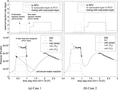
Figure 7. Calculation results of core debris temperature and the PCV pressures of the Unit 1 reactor for the boundary conditions of Case 2 specified in Table 2.
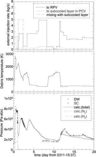
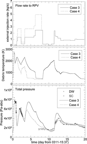
Figure 8. Calculation results of core debris temperature and the PCV pressures of the Unit 1 reactor for the boundary condition of Case 3 (solid lines) and Case 4 (dashed lines) specified in Table 2 assuming that the external water injection rate was reduced by half during the entire calculation period (Case 3) and the period after 8.0 days (Case 4).
It should be noted that a large part of the fuel presumably relocated to the pedestal because of the absence of the core cooling lasting almost 14 h (0.59 day) [Citation3,Citation12]. The present analysis, however, simulates only the vapor generations in the hot cans representing the RPV and the PCV for simplicity. In general, effects of the vapor generation due to the decay heat release on the PCV pressure do not depend on where the vapor is generated. The vapor generation in the hot can especially for the RPV in the present analysis, therefore, should be interpreted as that occurred somewhere in the PCV having a geometry similar to the RPV. In future, more detailed analysis will be conducted by adding a hot can simulating the pedestal.
Calculated PCV pressures for Case 1 are compared with the observed pressures in the drywell (DW) and the SC in . The RPV became empty of liquid at 0.4 day. Before this time, the large leakage pass between the RPV and the PCV were opened at 0.23 day to simulate the RPV failure, which did not affect the maximum PCV pressure. The figure shows that the PCV pressure increased rapidly after 0.3 day due to the assumed zirconium–water reaction, which caused the increase in the partial pressure of hydrogen. The calculated maximum pressure was, however, much lower than the measured value despite the assumed excess zirconium–water reaction and discharge of all the fluid from the RPV after the RPV failure.
The effect of the thermal stratification was investigated for Case 2, for which the liquid volume of 40% in the SC was assumed to have no effect on the heat transfer in reference to the SRV outlet elevation of a similar type of Mark-I plant with a different thermal power [Citation13]. shows that the peak pressure was much better reproduced for Case 2, indicating a significance of the thermal stratification effect on the PCV pressure.
The second topic for the Unit 1 analysis was a temporal pressure increase observed between 11.5 and 12.5 days. Although the plant situation was much improved during this time period, the cause for the temporal increase was not well understood. A possible cause may be suggested from relatively low injection rates between 8.3 and 11.3 days reported by TEPCO [Citation11], during which the water injection rates were smaller than those required for the decay heat removal. If this was the case, the fuel debris temperature might have increased during this time period, and the increase of the water injection after this might have increased the vapor generation resulting in the temporal pressure increase. It should be noted that similar reduction of the water injection rate was also recorded between 9.3 and 13.3 at Unit 3, which was later denied by TEPCO [Citation14]. The possibility of the above-mentioned scenario was investigated in the present analysis since the published water injection rates are believed to have large uncertainties [Citation12,Citation15].
shows comparisons of the calculated and measured data for Case 2 up to 20 days from the SBO. The temporal pressure increase was underestimated, indicating the underestimation of the heat accumulation in the debris if the above-mentioned scenario was true. In order to increase the accumulated heat, the Case 3 calculation assumed that the water injection rate reduced by half from the beginning of the calculation. As shown in , the pressure during the focused period increased as expected but was overestimated for the Case 3. Furthermore, the pressure between 7 and 10 days were also overestimated. The water injection rate was reduced by half only after 8.0 days to improve these discrepancies. The results of this case (corresponding to Case 4 in ) were also plotted in by dashed lines, showing improved estimations both for the maximum pressure during the temporal pressure increase period and the pressure between 7 and 10 days.
3.2. Analysis for the Unit 2 reactor
The PCV pressure during the first three days were focused for the analysis of the Unit 2 reactor, during which the reactor core isolation cooling (RCIC) systems were successfully operated to remove the core decay heat. The water source of the RCIC was changed from the condensate storage tank (CST) to the SC at 4:20 to 5:00 on March 12 (0.56 to 0.59 day after the reactor scram of the Unit 2), which was modeled in the analysis. It was presumed that the openings of the isolation valves in the RCIC system were fixed in as-is when the tsunami removed all the power sources at the Unit 2. This is believed to be a cause for the observed RPV pressure behavior that was different from that expected from the RCIC normal operation procedure. This difference was not taken into account in this analysis; the pressure was maintained around the SRV operation pressure and the water injection was adjusted to have a constant liquid level in the RPV. Since this analysis is focused on the PCV pressure, the detail of the RPV behavior does not affect the PCV behavior as long as the decay heat is transferred to the PCV in the calculation.
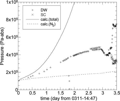
shows the calculated PCV pressures assuming adiabatic conditions: no heat removal and no leakage from the PCV, which were much higher than the measured pressures. In order to investigate the cause of the overestimation, two calculations were conducted using the following assumptions:
Case 1: Leakage from the PCV was assumed to occur 21 hours after the reactor scram (0.88 day) with the area corresponding to 78 mm in diameter. | |||||
Case 2: Outer surface of the SC was assumed to be cooled by the stagnation water accumulated in the torus room. The water level was fixed at 1.25 m, corresponding to 1/8 of the SC total height. The fluid temperature was increased linearly from 283 to 373 K in 2.5 days. | |||||
Figure 9. Calculated PCV pressure for the Units 2 reactor assuming adiabatic conditions: no heat removal and no leakage from the PCV.
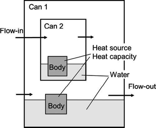
Regarding Case 2, the TEPCO also mentioned a possibility of sea water invasion into the torus room around the SC and its effect on the PCV pressure using a boundary condition different from the present analysis [Citation9,Citation16]. The heat transfer model of Case 2 is illustrated in . The wall was assumed to be cooled under a specified water level in the torus room and adiabatic above the level. The heat transfer mode such as convection or nucleate boiling was evaluated from the SC wall temperature calculated based on the assumption of steady-state heat balance expressed as,
shows the two comparison results between calculation and the observation data. The PCV pressure for both cases agrees well with the measured data until the SRV opens. The partial pressure of the nitrogen gas for Case 1 decreased immediately after the discharge hole opened, while for Case 2 it was nearly constant due to no leakage. These calculation results indicate a strong possibility that the PCV was cooled by the water accumulated in the torus room and/or the leakage to the atmosphere.
Figure 10. Illustration of wall heat transfer model for the analysis of the Unit 2 reactor (the case of flooding into the torus room).
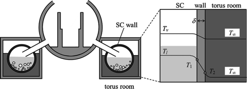
Figure 11. Calculation results of RPV and PCV pressures for the analysis of the Unit 2 reactor. (a) Case 1: assuming heat loss by gas leakage from the PCV, (b) Case 2: assuming heat loss by heat transfer on the SC outer surface.
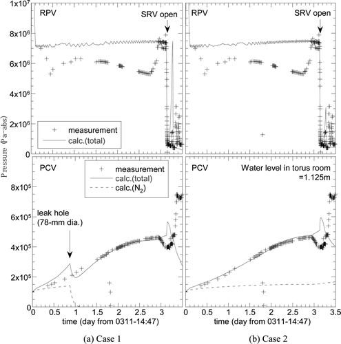
As shown in , the calculated PCV peak pressure was much lower than the data after the SRV was opened. This was probably caused by the absence of a hydrogen generation model for this analysis.
4. Conclusion
A simple code, named “HOTCB”, was developed to estimate thermal-hydraulic transients in the Fukushima Dai-ichi NPP accident. The numerical model was based on mass and heat balances in a lamped parameter system of single-phase fluid or thermally equilibrium two-phase fluid in a vessel to realize robust numerical simulation with very short CPU time. The code has capabilities to treat heat transfer between heat structures and fluids, and also to take a superheat state beyond saturation into account to evaluate the extent of reactor core damage. Analysis results for accident progression of the Unit 1 and Unit 2 reactors were presented in this paper as examples showing the usefulness of the code to understand the accident behavior. That is, causes of pressure responses and important parameters such as leak sizes are presumed from agreements of the calculated and measured pressures of the containment vessel.
The HOTCB code was distributed to members of TEPCO's headquarters and was practically used for accident analysis. From the expectation to be more widely used for the analysis on this accident, the HOTCB code is publicly available at JAEA's website [Citation17] as an open source code.
Nomenclature
| A : | = |
leak hole's area of a can |
| Acr : | = |
cross-sectional area of a body |
| Asf : | = |
surface area of a body |
| Cpl, Cpv, Cp : | = |
specific heat of water, vapor, or a body |
| ek : | = |
specific internal energy of component k |
| E : | = |
total internal energy in a can |
| f : | = |
geometric factor of a body |
| fwet : | = |
submerged fraction of a body under a water level |
| H : | = |
heat transfer coefficient |
| hl : | = |
water level |
| lL : | = |
|
| ll : | = |
Characteristic length |
| mk : | = |
mass of component k |
|
| = |
mass flow rates of flow-in (ik) and -out (ok) of component k |
|
| = |
evaporation rate of water |
|
| = |
mixing rate of subcooled water into saturated water |
| pc : | = |
critical pressure defined in Equation (21) |
| pk : | = |
partial pressure of each component k |
| pt : | = |
total pressure of gas phase |
| Pr : | = |
Prandtl number |
|
| = |
heat generation rate of heat source in a can |
|
| = |
heat generation rate of a body |
| q′′ : | = |
surface heat flux of a body |
| Ra : | = |
Raleigh number |
| Tav : | = |
average temperature of a body (Tdrt, Twet for dry and wet zone) |
| Tiv, Tin, Tini, Til : | = |
temperatures of flow-in fluids |
| Tlc : | = |
subcooled water temperature; temperature and its change rate are given from inputs |
| Tsat ( = Tv = Tn = Tni = Tl ) : | = |
temperatures of saturation system; the gas and saturated water are the same saturation temperature |
| Tsf : | = |
surface temperature of a body (Tdsf, Twsf for dry and wet zone) |
| Vbody : | = |
total volume of a body |
| Vcan : | = |
total volume of a can (vessel volume) |
| Vg : | = |
gas volume (common for each gas component) |
| Vl ,Vlc : | = |
water volume of saturation or subcool |
Greek symbol
| γ : | = |
specific heat ratio |
| ϵ rad : | = |
emissivity |
| δ : | = |
thickness of thermal boundary layer or wall |
| λ : | = |
thermal conductivity of a body |
| ν : | = |
kinematic viscosity |
| σ l : | = |
surface tension |
| σ SB : | = |
Stefan–Boltzmann constant |
| ρ body : | = |
densities of a body |
| ρ k : | = |
densities of each component k |
| ρ ik : | = |
densities of flow-in fluids (at the total pressure and the temperature of each flow-in fluid) |
| Δhfg : | = |
latent heat of water |
| Δt : | = |
time step |
Subscripts
| c : | = |
fluid surrounding a body |
| l : | = |
water (saturation) |
| lc : | = |
water (subcool) |
| n : | = |
non-condensable gas (injected from outside, e.g. nitrogen) |
| ni : | = |
non-condensable gas (produced inside can, e.g. hydrogen) |
| v : | = |
vapor |
| dry : | = |
dry zone exposed to gas phase |
| wet : | = |
wet zone under water level |
References
- U.S. Nuclear Regulatory Commission / Idaho National Engineering Laboratory . 1995 . RELAP5/MOD3 Code Manual NUREG/CR-5535 / INEL-95/0174
- Giles , M.M. , Jayne , G.A. , Rouhani , S.Z. , Shumway , R.W. , Singer , G.L. , Yaylor , D.D. and Weaver , W.L. 1992 . TRAC-BF1/MOD1: An Advanced Best-Estimate Computer Program for BWR Accident Analysis , NUREG/CR-4356 .
- Hirano , M. , Yonomoto , T. , Ishigaki , M. , Watanabe , N. , Maruyama , Y. , Sibamoto , Y. , Watanabe , T. and Moriyama , K. 2012 . Insights from review and analysis of the Fukushima Dai-ichi accident . J. Nucl. Sci. Technol , 49 : 1 – 17 .
- Moriyama , K. , Maruyama , Y. and Nakamura , H. 2008 . Steam explosion simulation code JASMINE v.3 user's guide , Japan Atomic Energy Agency . JAEA-Data/Code 2008-014
- Incropera , F.P. , Dewitt , D.P. , Bergman , T.L. and Lavine , A.S. 2007 . Fundamentals of Heat and Mass Transfer , 6th ed. , New York , NY : John Wiley & Sons Inc. .
- Kutateladze , S.S. 1952 . Heat Transfer in Condensation and Boiling, ACE-tr-3770 , US AEC .
- Berenson , P.J. 1961 . Film boiling heat transfer from a horizontal surface . J. Heat Transf , 83 : 351 – 358 .
- Nuclear Emergency Response Headquarters Government of Japan . 2011 . Report of the Japanese Government to the IAEA Ministerial Conference on Nuclear Safety , Tokyo : Government of Japan .
- TEPCO . Estimation reactor core and containment vessel condition by MAAP code Available at http://www.tepco.co.jp/nu/fukushima-np/images/handouts_120312_02-j.pdf [in Japanese]
- Way , K. and Wigner , E.P. 1948 . The rate of decay of fission products . Phys. Rev , 73 : 1318 – 1330 .
- TEPCO . Summary of actual manipulation results Available at http://www.tepco.co.jp/en/nu/fukushima-np/plant-data/f1_7_Sousajisseki_20110613teisei.pdf
- TEPCO . The evaluation status of reactor core damage at Fukushima Daiichi Nuclear Power Station Units 1 to 3 Available at http://www.tepco.co.jp/en/nu/fukushima-np/images/handouts_111130_04-e.pdf
- Powers , D.A. 1996 . A simplified model of decontamination by BWR steam suppression pools NUREG/CR-6153
- TEPCO . Fukushima Daiichi Unit 3 10 days after the earthquake disaster View on Core Re-melting Available at http://www.tepco.co.jp/en/nu/fukushima-np/images/handouts_110909_04-e.pdf
- Hoshi , H. The evaluation on reactor core condition at units 1, 2 and 3 reactor for the accident of the Fukushima Daiichi Nuclear Power Plant of TEPCO Available at http://www.nisa.meti.go.jp/shingikai/700/12/001/1-6-1.pdf [in Japanese]
- TEPCO . The investigation results of the accident situation and progress at Fukushima Daiichi Nuclear Power Plant Available at http://www.tepco.co.jp/cc/press/betu11_j/images/111222n.pdf [in Japanese]
- http://www.jaea.go.jp/04/anzen/hotcb/index.html [in Japanese]
- Oe , S. 1985 . Bussei-teisu-suisan-ho (Methods to estimate physical properties for designer) Nikkan-kogyo-shinbun-sha [in Japanese]
Appendix 1. Numerical solution method
The code carries out integrating the mass and energy equation with explicit integration scheme in terms of time and obtains the mass of each component and the total internal energy at the new time step, except that the phase change term is left unsolved with implicit scheme. After that, it solves the conservation and state equations at the new time step by Newton–Raphson method and obtains the phase change mass, pressures and volumes. From the mass equations from Equations (1) to (5), the following explicit integration are obtained,
where the superscripts (n + 1) and (n) denote new and old time step variables, * denotes the intermediate values including changes except the phase change term. The energy Equation (8) does not include the phase change term explicitly and dE/dt of Equation (9) can be calculated from the old time variables. Thus, the total internal energy at the new time step is obtained by
It is also expressed as the sum of internal energies of components in the new time step that are unknown.
The known masses at new time step (n + 1) except for are substituted in this equation. Each specific internal energy is the function of the partial pressure. Then, the following equations with Δmev, pv, pn, pni, Vg
, and Vl
as primary variables are to be solved.
The subcooled water density and volume denoted by subscript lc are known because temperature is given externally. This simultaneous equation set is solved by the Newtonian iteration. The linear equation set for the corrections of primary variables is solved by Gaussian elimination method.
Appendix 2. Remedies for numerical instability attributed to model simplification
A remedy for the case with diminishing saturated water
When the water in the saturation system is totally evaporated, the mass ml
becomes negative in the solution procedure of the equations for the primary variables (F
1 to F
6 equations in Appendix 1.). This situation is detected in the Newtonian iteration by forcing ml
= 0 instead of negative ml
and failing in convergence. When this happens, (the total water mass should be the vapor) and
are applied. The gas volume
also becomes known. Then, the following modified equation set is solved with the vapor state equation allowing superheated condition.
The primary variables in this case are Tg, pv, pn, pni . The temperature is common for all the gas components.
This model may give an underestimate of the gas-phase temperature which can be rather non-conservative. It is because the gas phase superheat state is allowed only after the whole water in the system is consumed completely, which may be different from actual situation and can delay the onset of wall heat up.
A remedy for the case with diminishing vapor
It is assumed that vapor always exists. Even when the temperature is below the saturation temperature at total pressure, vapor with the partial pressure that equals to the saturation pressure at the low temperature exists. However, flow-out of non-condensable gases accompanying the vapor sometimes causes very low vapor pressure that is now allowed by the steam table. To prevent failure of the solution, the vapor flow-out is stopped arbitrarily in the case the vapor pressure becomes close to the lower limit of the steam table range, 614 Pa. This remedy does not cause practical problem.
Appendix 3. Viscosity and thermal conductivity of ideal gases and gas mixtures
We need viscosity and thermal conductivity for heat transfer calculations. Those physical properties for gases other than steam are evaluated with the following equations [18]. Viscosity is
where M is molecular weight (kg/mol); T is absolute temperature (K); σ is a molecular diameter as a rigid sphere (Angstrom) and equals 3.711 for air, 3.798 for nitrogen, 3.467 for oxygen, 2.827 for hydrogen, and 3.941 for CO2. Ω v is collision integral for non-polar gases given by
where ϵ/kB (K) equals 78.6 for air, 71.4 for nitrogen, 106.7 for oxygen, 59.7 for hydrogen, and 195.2 for CO2. Thermal conductivity is
where R is the general gas constant (the unit is J/mol-K). The viscosity and heat conductivity for a gas mixture are evaluated by the following,
where yi is molar fraction of component i, Si = 1.5Tbi, Sij = Sji = Cs (SiSj )1/2, and Cs = 1 (Cs = 0.73, if including highly polar component). Tbi is boiling point of component i.
