Abstract
The boiling water reactors (BWRs) have steam dryer in the upper part of the pressure vessel to remove moisture from the steam. The steam dryer in the Quad Cities Unit 2 nuclear power plant was damaged by high-cycle fatigue due to acoustic-induced vibration during extended power uprate operation. The principal source of the acoustic-induced vibration was flow-acoustic resonance at the stub pipes of the safety relief valves (SRVs) in the main steam lines (MSLs). The acoustic wave generated at the SRV stub pipes propagates throughout the MSLs and eventually reaches and damages the steam dryer. Therefore, for power uprate operation of the BWRs, it has been required to predict the flow-acoustic resonance at the SRV stub pipes. The purpose of this article was to propose a numerical analysis method for evaluating the flow-acoustic resonance in the SRV stub pipes. The proposed method is based on the finite difference lattice Boltzmann method (FDLBM). So far, the FDLBM has been applied to flow-acoustic simulations of laminar flows around simple geometries at low Reynolds number. In order to apply the FDLBM to the flow-acoustic resonance simulations of turbulent flows around complicated geometries at the high Reynolds number, we developed computationally efficient model by introducing new function into the governing equation. The proposed method was compared with the conventional FDLBM in the cavity-driven flow simulation. The proposed method was validated by comparisons with the experimental data in the 1/10-scale test of BWR-5 under atmosphere condition. The following three results were obtained; the first is that the proposed method can reduce the computing time by 30% compared with the conventional FDLBM; the second is that the proposed method successfully simulated the flow-acoustic resonance in the SRV stub pipes of the BWR-5, and the pressure fluctuations of the simulation results agreed well with those of the experimental data; and the third is the mechanism of the flow-acoustic resonance in the SRV stub pipes. Acoustic waves causing the flow-acoustic resonance in the SRV stub pipes are generated by the unsteady vortices in the SRV stub pipes.
1. Introduction
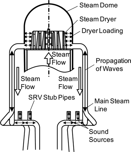
In recent years, extended power uprate (EPU) operation has been implemented in many boiling water reactors (BWRs) in the United States. The BWR in the Quad Cities Unit 2 (QC-2) experienced a significant increase in steam moisture in the main steam lines (MSLs) at EPU operation [Citation1]. Inspection showed that the steam dryer which is installed in the upper part of the pressure vessel had been damaged by high-cycle fatigue due to acoustic-induced vibration. DeBoo et al. [Citation2] investigated sound sources of the acoustic-induced vibration using actual plant data. Their results showed that the principal source was flow-acoustic resonance at the stub pipes of the safety relief valves (SRVs) in the MSLs. It was likely that the acoustic wave generated in the SRV stub pipes propagated from the SRV stub pipes to the steam dryer throughout the MSLs and eventually reached and damaged the steam dryer (). Therefore, for power uprate operation of the BWRs, the flow-acoustic resonance at the SRV stub pipes needs to be predicted. We have started a research program to develop evaluation methods for the steam dryer vibration [Citation3]. The purpose of this article is to propose a numerical analysis method for evaluating the flow-acoustic resonance in the SRV stub pipes.
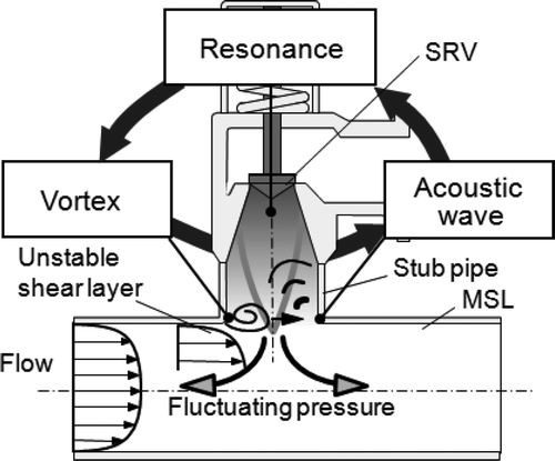
The flow-acoustic resonance may occur in a piping system with closed side branches, such as the SRV stub pipe. The flow-acoustic resonance is produced by interaction between acoustic wave and an unstable shear layer across the SRV stub pipe (). The unstable shear layer promotes and enhances the formation of vortices in the SRV stub pipe. These vortices trigger the formation of the acoustic wave. If the vortex shedding frequency is close to the acoustic resonance frequency of the SRV stub pipe, the vortex shedding frequency is locked in the acoustic resonance frequency and then the flow-acoustic resonance occurs. When the resonance occurs, the amplitude of the acoustic wave can be several times higher than the dynamic pressure in the MSLs. Many experimental studies [Citation4–Citation10] related to flow-acoustic resonance of closed side branches have been reported. Jungowski et al. [Citation4] investigated the effect of the diameter ratio on the Strouhal number and the amplitude of the acoustic wave. Bruggeman et al. [Citation5] proposed a theoretical model for the acoustic sources responsible for the flow-acoustic resonance in a piping system with closed side branches. Ziada and Buhlmann [Citation6] demonstrated that side branches in close proximity are particularly liable to resonance. Kriesels et al. [Citation7] studied the detailed behavior of the flow in a piping system with two opposite closed side branches of equal length in a cross configuration. Visualization of the flow-acoustic resonance was also studied by Ziada [Citation8], Dequand et al. [Citation9], and Li et al. [Citation10].
On the other hand, a numerical analysis is helpful for the prediction of occurrence of the flow-acoustic resonance and the easy understanding of phenomena of the flow-acoustic resonance in the stub pipes of the SRVs. However, a numerical analysis of the flow-acoustic resonance is difficult due to the need to capture interaction between the vortex and the acoustic wave in the SRV stub pipe. In particular, pressure fluctuations of the acoustic wave are very small compared with those of the vortex when the flow-acoustic resonance begins to occur. Therefore, the numerical analysis method which can accurately capture the acoustic wave is required for the flow-acoustic simulations. The compact finite difference scheme [Citation11–Citation16] is often applied to the computational aero-acoustics (CAA) simulations. However, the compact finite difference scheme is liable to become unstable and requires large computational effort compared with the traditional finite difference schemes due to its implicit algorithms [Citation17]. Recently, the finite difference lattice Boltzmann method (FDLBM) [Citation18–Citation26] has been verified as an alternative method which can accurately capture the acoustic wave. The FDLBM is the numerical analysis method which is developed from the lattice Boltzmann method (LBM) [Citation27–Citation38]. Unlike conventional computational fluid dynamics (CFD) methods based on discretizations of the fluid dynamics equations, the LBM is based on the kinetic equation of the molecular gas dynamics. Chen and Doolen [Citation38] presented the view that the LBM is not only computationally comparable with traditional numerical analysis methods, but it is also easy to program and to include new physics because of the simple form of the equation of this method. The FDLBM in which the kinetic equation is discretized by the finite difference scheme has been developed for improvements of numerical stability of the LBM. Tsutahara et al. [Citation23] has reported that interaction between the vortex and the acoustic wave can be well captured by the FDLBM in the simulation of the flow around the two-dimensional circular cylinder.
The FDLBM is considered to be appropriate to the numerical analysis method for the flow-acoustic resonance simulations at the SRV stub pipes. However, so far, the FDLBM has been applied to flow-acoustic simulations of laminar flows around simple geometries such as two-dimensional circular cylinder at low Reynolds number because of its computational cost [Citation23]. In this article, we developed computationally efficient model in order to apply the FDLBM to the flow-acoustic resonance simulations of turbulent flows around complicated geometries such as the SRV stub pipes. The developed method was compared with the conventional FDLBM in the cavity-driven flow simulation. The developed method was validated by comparisons with the experimental data in the 1/10-scale test of BWR-5 under atmosphere condition. The mechanism of the flow-acoustic resonance at the SRV stub pipes was also discussed by the simulation results.
2. Numerical method
2.1. Finite difference Lattice Boltzmann method
In this section, we introduce the FDLBM developed by Tsutahara et al. [Citation23] The FDLBM is different from traditional CFD methods and is based on the molecular gas dynamics. The FDLBM can be derived from the Boltzmann equation which is a basic equation of the molecular gas dynamics. In the FDLBM, the density ρ and the flow velocity u α are given from the velocity distribution function fi taking the moments of the molecular velocities ci α as
The equation to be solved in the FDLBM is the following kinetic equation (discrete-velocity Bhatnagar-Gross-Krook (BGK) equation):
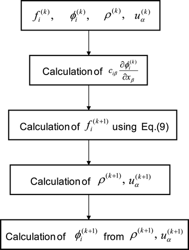
Figure 3. Calculation procedure of the conventional FDLBM [Citation23].
![Figure 3. Calculation procedure of the conventional FDLBM [Citation23].](/cms/asset/f13f90a3-87ac-48d0-9195-3d7c217f27c9/tnst_a_703943_o_f0003g.gif)
2.2. Computational acceleration
In order to apply the FDLBM to the numerical analysis of the flow-acoustic resonance at the SRV stub pipes, there is the need for improvements of its computational efficiency. In this section, we develop improvements for computational acceleration of the FDLBM. Most of the computations of the FDLBM are occupied by the calculation of the spatial-derivative terms and the calculation of the equilibrium distribution function. Equation (3) includes three spatial-derivative terms. Uniting these derivative terms leads to computational acceleration of the FDLBM. To do this, we proposed a new function φ
i
instead of the equilibrium distribution function . The new function consists of the distribution function and the equilibrium distribution function.
Figure 5. Distribution of the molecule velocities ci α [Citation26].
![Figure 5. Distribution of the molecule velocities ci α [Citation26].](/cms/asset/9b10f7c3-6d74-48b6-98d8-713c65e12190/tnst_a_703943_o_f0005g.gif)
Table 1. Cartesian components of the molecule velocities [Citation26], where  and
and  .
.
The four-stage second-order Runge-Kutta method is used for the time integration of Equation (9) because we can use a large Courant-Friedricks-Lewey (CFL) number cΔt/Δx in three-dimensional simulations compared with the two-stage second-order Runge-Kuuta method. The four-stage second-order Runge-Kutta method is as follows.
In order to increase simulation accuracy, the spatial derivative of Equation (9) is discretized by the sixth-order central-difference scheme as follows.
The turbulent viscosity is calculated by the lattice Boltzmann subgrid model [Citation38]. As the lattice Boltzmann subgrid model, we employ the Smagorinsky eddy viscosity model, which computes the turbulent viscosity μ T from the local shear rate and the filter size:
2.3. Validation of the developed method
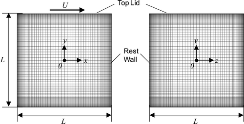
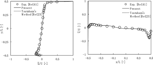
In this section, the proposed method is compared with the FDLBM developed by Tsutahara et al. [Citation23] with respect to computational efficiency. Both methods are discretized by the same numerical schemes. Comparison between the developed method and Tsutahara's method is shown in . The analysis object is the cavity-driven flow at the Reynolds number of 12,000 [Citation41]. The flow is induced by the top lid that moves in the x-direction. The non-uniform grid for the computation is shown in . The grid number is 71×71×71, and the minimum grid width is 0.002L. The CFL number is 1.0. On the rest wall, the non-slip boundary condition is applied. On the top lid, the Neumann type boundary condition is applied for the density and the velocity is constant. The flow velocity of the simulation results are shown in . Both simulation results agree well with the experimental result. The developed method can reduce the computing time by 30% compared with the conventional FDLBM.
Table 2. Comparison between the developed method and the conventional FDLBM [Citation23].
3. Acoustic resonance simulations
3.1. Analysis conditions
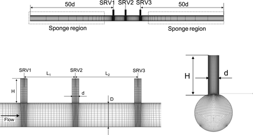
We applied the developed method to simulations of the flow-acoustic resonance in the SRV stub pipes. Our analysis object is the SRV stub pipes of the 1/10-scale test apparatus [Citation3] illustrated in . The 1/10-scale test apparatus was made with reference to a BWR-5. In these simulations, we focused on the SRV stub pipes which consist of three side branches. The configuration of the SRV stub pipes is shown in (b). Fluctuating pressures induced by the flow-acoustic resonance are measured on the top of the three stub pipes. Air at ordinary temperature is used as fluid instead of steam flow. Physical properties of the fluid are shown in .
Figure 8. Schematic presentation of the test facility [Citation3].
![Figure 8. Schematic presentation of the test facility [Citation3].](/cms/asset/b37c38ea-893d-4ed8-8dd7-ccf0b1efb0e8/tnst_a_703943_o_f0008g.gif)
Table 3. Physical properties of the fluid.
The multi-block structure grid which is shown in is used for three-dimensional simulations of the flow-acoustic resonance in the SRV stub pipes. The total number of grid points is about 1,500,000. The non-dimensional minimum grid width Δx/d is 0.01. The CFL number is 1.0. On the wall boundary, the flow velocity is given by the wall function defined by the Spaulding law and the density is given by the Neumann type boundary condition. On the inlet boundary, the velocity is constant and the Neumann type boundary condition is applied for the density. On the outlet boundary, the density is constant and the Neumann type boundary condition is applied for the velocity. In order to prevent acoustic waves generated in the SRV stub pipes from reflecting at inlet or outlet boundaries, sponge regions which attenuate the acoustic waves by numerical viscosity are placed as shown in (a).
The non-dimensional parameters of this problem are the Reynolds number Re and the Strouhal number St. The Strouhal number St is defined by the following equation:
3.2. Results and discussion
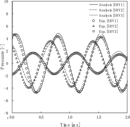
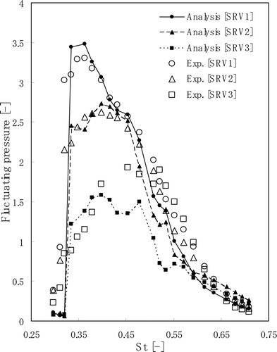
We note that the large fluctuating pressure induced by the flow-acoustic resonance occurs at the flow condition under which the flow velocity is excessively increased compared with the velocity at normal operation. Time variation of pressure fluctuations on the top of the SRV stub pipes at the Strouhal number of 0.36 is shown in . The pressure is normalized by the dynamic pressure in the main pipe. The results show a substantial sinusoidal waveform. Large pressure fluctuations occur due to the flow-acoustic resonance in the SRV stub pipes. The numerical results show good agreement with the experimental data. The amplitudes of the pressure fluctuations defined as effective value of time variation of pressure fluctuations are plotted against the Strouhal number in . The stub pipe of SRV1 placed upstream induces the largest pressure fluctuation. The amplitude of the pressure fluctuation becomes 3.5. The Strouhal number corresponding to the largest fluctuating pressure is approximately 0.36. The numerical results of SRV1 and SRV2 show good agreement with the experimental data. The numerical results of SRV3 are slightly different from the experimental data. The reason is likely that SRV3 is affected by vortices which come from SRV1 and SRV2.
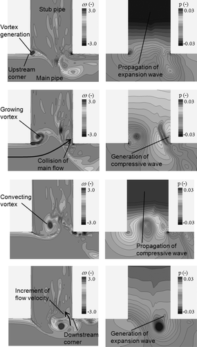
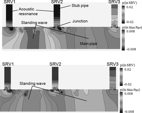
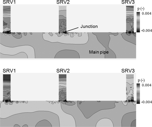
In order to investigate the mechanism of the flow-acoustic resonance, we show vorticity field and pressure field of the SRV1 of the simulation results in , where T represents the cycle of the unsteady vortex motion. The vorticity ω is non-dimensionalized by the diameter of the stub pipe d and the speed of sound c. The pressure p is non-dimensionalized by c 2 and the density ρ. Anti-clockwise vorticity is defined as positive. The Strouhal number is 0.36 which corresponds to the flow condition where the largest fluctuating pressure occurs in these simulations and experiments. The vortex is periodically generated at the upstream corner ((a)). The vortex grows and is convected downward ((b) and (c)). Finally, the vortex moves into the main pipe, passing through the neighborhood of the downstream corner ((d)). When the vortex is located at the upstream corner, a compressive wave is generated around the downstream corner due to collision of the main flow with the downstream corner ((b)). When the vortex is located at the downstream corner, the flow velocity around the downstream corner is increased by the vortex-induced velocity. As a result, an expansion wave is generated around the downstream corner. Acoustic resonance in the SRV stub pipes is shown in . The first quarter-wave resonance occurs in all stub pipes. The standing wave is observed between SRV1 and SRV2 because their phases are almost the same. Pressure distribution in the SRV stub pipes at the Strouhal number of 0.29 which corresponds to the flow condition of the small pressure fluctuations is shown in . The first quarter-wave resonance does not occur in all stub pipes. The standing wave in the main pipe is not observed in this case.
4. Conclusions
In this article, we proposed a numerical analysis method based on the FDLBM for evaluating the flow-acoustic resonance in the SRV stub pipes. In order to apply the FDLBM to the flow-acoustic resonance simulations, we developed computationally efficient model by introducing new function into the governing equation. The developed method was compared with the conventional FDLBM in the cavity-driven flow. The developed method was validated by comparisons with the experimental data in the 1/10-scale test of BWR-5. The mechanism of the flow-acoustic resonance was also discussed by the simulation results. The following results were obtained.
| 1. | In order to increase computational efficiency of the FDLBM, we developed a new function which consists of the distribution function and the equilibrium distribution function. The simplified governing equation of the FDLBM was proposed by introducing the new function. It was found that the developed method can reduce the computing time by 30% compared with the conventional FDLBM. | ||||
| 2. | The developed method was applied to the numerical analyses of the flow-acoustic resonance in the SRV stub pipes of the 1/10-scale test of BWR-5. The developed method successfully simulated the flow-acoustic resonance at the SRV stub pipes of the BWR-5. Time variation of the pressure fluctuations becomes substantially sinusoidal waveform. The pressure fluctuations of the simulation results agreed well with those of the experimental data. | ||||
| 3. | Acoustic waves causing the flow-acoustic resonance in the SRV stub pipes were generated by the unsteady vortices in the SRV stub pipes. When the vortex was located at the upstream corner, a compressive wave was generated around the downstream corner due to a collision of the main flow with the downstream corner. When the vortex was located at the downstream corner, the flow velocity around the downstream corner was increased by the vortex-induced velocity. As a result, an expansion wave was generated around the downstream corner. | ||||
Acknowledgements
We would like to thank Prof. Fujii and Dr. Nonomura of ISAS-JAXA for many enlightening discussions about the compact finite difference scheme and insightful comments.
References
- 2006 . Q2R18 concerns related to steam dryer Washington , DC LS-AA-125-1001 Revision 5, NRC
- DeBoo , G. , Ramsden , K. and Gesior , R. 2006 . Quad Cities Unit 2 main steam line acoustic source identification and load reduction . Proceedings of ICONE-14 . July 17–20 2006 .
- Takahashi , S. and M. Ohtsuka, K. Okuyama, T. Ito, and K. Yoshikawa, . 2008 . Experimental study of acoustic and flow-induced vibrations in BWR main steam lines and steam dryers . Proceedings of PVP2008 . July 27–31 2008 .
- Jungowski , W.M. , Botros , K.K. and Studzinski , W. 1989 . Cylindrical side-branch as tone generator . J. Sound Vib , 131 : 265 – 285 .
- Bruggeman , J.C. , Hirschberg , A. , van Dongen , M.E.H. , Wijnands , A.P.J. and Gorter , J. 1991 . Self-sustained aero-acoustic pulsations in gas transport systems: Experimental study of the influence of closed side branches . J. Sound Vib , 150 : 371 – 393 .
- Ziada , S. and Buhlmann , E.T. 1992 . Self-excited resonances of two side-branches in close proximity . J. Fluids Struct , 6 : 583 – 601 .
- Kriesels , P.C. , Peters , M.C.A.M. , Hirschberg , A. , Wijnands , A.P.J. , Iafrati , A. , Riccardi , G. , Piva , R. and Bruggeman , J.C. 1995 . High amplitude vortex-induced pulsations in a gas transport system . J. Sound Vib , 184 : 343 – 368 .
- Ziada , S. 1994 . A flow visualization study of flow-acoustic coupling at the mouth of a resonant side-branch . J. Fluids Struct , 8 : 391 – 416 .
- Dequand , S. , Hulshoff , S.J. and Hirshberg , A. 2003 . Self-sustained oscillations in a closed side branch system . J. Sound Vib , 265 : 359 – 386 .
- Li , Y. , Someya , S. and Okamoto , K. 2008 . A visualization study of flow-induced acoustic resonance in a branched pipe . Proceedings of NTHAS-6 . November 24–27 2008 .
- Nonomura , T. and Fujii , K. 2009 . Effects of difference scheme type in high-order weighted compact nonlinear schemes . J. Comput. Phys , 228 ( 10 ) : 3533 – 3539 .
- Nonomura , T. , Iizuka , N. and Fujii , K. 2010 . Freestream and vortex preservation properties of high-order WENO and WCNS on curvilinear grids . Comput. Fluids , 39 ( 2 ) : 197 – 214 .
- Nonomura , T. , Muranaka , H. and Fujii , K. 2010 . Computational analysis of Mach number effects on the edgetone phenomenon . AIAA J , 48 ( 6 ) : 1248 – 1251 .
- Kawai , S. and Fujii , K. 2008 . Compact scheme with filtering for large-eddy simulation of transitional boundary layer . AIAA J , 46 ( 3 ) : 690 – 700 .
- Yokoyama , H. , Tsukamoto , Y. , Kato , C. and Iida , A. 2007 . Self-sustained oscillations with acoustic feedback in flow over a backward-facing step with a small upstream step . Phys. Fluids , 19
- Yokoyama , H. and Kato , C. 2009 . Fluid-acoustic interactions in self-sustained oscillations in turbulent cavity flows. I: Fluid-dynamic oscillations . Phys. Fluids , 21 : 105103
- Bogey , C. and Bailly , C. 2004 . A family of low dispersive and low dissipative explicit schemes for flow and noise computations . J. Comput. Phys , 194 ( 1 ) : 194 – 214 .
- Nannelli , F. and Succi , S. 1992 . The lattice Boltzmann equation on irregular lattices . J. Stat. Phys , 68 ( 3 ) : 401 – 407 .
- Reider , M.B. and Sterling , J.D. 1995 . Accuracy of discrete-velocity BGK models for the simulation of the incompressible Navier-Stokes equations . Comput. Fluids , 24 : 459 – 467 .
- Cao , N. , Chen , S. , Jin , S. and Martinez , D. 1997 . Physical symmetry and lattice symmetry in the lattice Boltzmann method . Phys. Rev. E , 55 : 21 – 24 .
- Watari , M. and Tsutahara , M. 2003 . Two-dimensional thermal model of the finite difference lattice Boltzmann method with high spatial isotropy . Phys. Rev. E , 67 : 036306
- Seta , T. and Takahashi , R. 2002 . Numerical stability analysis of FDLBM . J. Stat. Phys , 107 : 557 – 572 .
- Tsutahara , M. , Kataoka , T. , Shikata , K. and Takada , N. 2008 . New model and scheme for compressible fluids of the finite difference lattice Boltzmann method and direct simulations of aerodynamic sound . Comput. Fluids , 37 : 79 – 89 .
- Tamura , A. and Tsutahara , M. 2010 . Direct simulation of Aeolian tones emitted from a circular cylinder in transonic flows using the finite difference lattice Boltzmann method . Fluid Dynam. Res , 42 : 015007
- Tamura , A. , Tsutahara , M. , Kataoka , T. , Aoyama , T. and Yang , C. 2008 . Numerical simulation of two-dimensional blade-vortex interactions using finite difference lattice Boltzmann method . AIAA J , 46 ( 9 ) : 2235 – 2247 .
- Tamura , A. , Okuyama , K. , Takahashi , S. and Ohtsuka , M. 2011 . Three-dimensional discrete -velocity BGK model for the incompressible Navier-Stokes equations . Comput. Fluids , 40 : 149 – 155 .
- McNamara , G. and Zanetti , G. 1988 . Use of the Boltzmann equation to simulate lattice-gas automata . Phys. Rev. Lett , 61 : 2332 – 2335 .
- Higuera , F.J. and Jimenez , J. 1989 . Boltzmann approach to lattice gas simulations . Europhys. Lett , 9 : 663 – 668 .
- Higuera , F.J. , Succi , S. and Benzi , R. 1989 . Lattice gas dynamics with enhanced collisions . Europhys. Lett , 9 : 345 – 349 .
- Benzi , R. , Succi , S. and Vergassola , M. 1992 . The lattice Boltzmann equation: Theory and applications . Phys. Rep. Lett , 222 : 145 – 197 .
- Chen , S. , Chen , H. , Martinez , D. and Matthaeus , W.H. 1991 . Lattice Boltzmann model for simulation of magnetohydrodynamics . Phys. Rev. Lett , 67 : 3776 – 3779 .
- Chen , H. , Chen , S. and Matthaeus , W.H. 1992 . Recovery of the Navier-Stokes equations using a lattice gas Boltzmann method . Phys. Rev. A , 45 : 5339 – 5342 .
- Qian , Y.H. , d'Humieres , D. and Lallemand , P. 1992 . Lattice BGK models for Navier-Stokes equation . Europhys. Lett , 17 : 479 – 484 .
- He , X. and Luo , L.S. 1997 . Theory of the lattice Boltzmann method: From the Boltzmann equation to the lattice Boltzmann equation . Phys. Rev. E , 56 : 6811 – 6817 .
- d'Humieres , D. , Bouzidi , M. and Lallemand , P. 2001 . Thirteen-velocity three-dimensional lattice Boltzmann model . Phys. Rev. E , 63 : 066702-1-7
- d'Humieres , D. , Ginzburg , I. , Krafczyk , M. , Lallemand , P. and Luo , L.S. 2002 . Multiple-relaxation-time lattice Boltzmann models in three dimensions . Phil. Trans. R. Soc. Lond. A , 360 : 437 – 451 .
- Guo , Z. , Zheng , C. and Shi , B. 2002 . An extrapolation method for boundary conditions in lattice Boltzmann method . Phys. Fluids , 14 : 2007 – 2010 .
- Chen , S. and Doolen , D. 1998 . Lattice Boltzmann method for fluid flows . Annu. Rev. Fluid Mech , 30 : 329 – 364 .
- Howe , M.S. 2003 . Theory of Vortex Sound , Cambridge : Cambridge University Press .
- Germano , M. , Piomelli , U. , Moin , P. and Cabot , W.H. 1991 . A dynamic subgrid-scale eddy viscosity model . Phys. Fluids , A3 ( 7 ) : 1760 – 1765 .
- Koseff , J.R. and Street , R.L. 1984 . Visualization studies of a shear driven three-dimensional recirculating flow . J. Fluids Eng , 12 : 1363 – 1376 .
