Abstract
The electrolytic reduction of spent oxide fuel involves the liberation of oxygen in a molten LiCl electrolyte, which results in a chemically aggressive environment that is too corrosive for typical alloying structural materials. Therefore, the choice of the optimum material for the processing equipment that handles molten salt is critical. We investigated the corrosion behaviors of CaO-stabilized ZrO2 (CSZ) and mullite (Al6Si2O13) at 650°C for 168 h in molten (1, 3) wt% Li2O–LiCl. The as-received and tested specimens were examined by scanning electron microscopy/X-ray energy dispersive spectrometry and X-ray diffraction. CSZ showed a much better hot-corrosion resistance in the presence of Li2O–LiCl molten salt than mullite. The surface corrosion layers of mullite consisted of LiAlSiO4 in 1 wt% Li2O–LiCl, and a LiAlO2 phase appeared as the Li2O concentration increased to 3 wt%. Furthermore, Li2SiO3 was the only corrosion product observed at 3 wt% Li2O–LiCl. The surface corrosion layers of CSZ were composed mainly of tetragonal-ZrO2 with partial monoclinic-ZrO2 in 1 wt% Li2O–LiCl, and a Li2ZrO3 phase appeared at 3 wt% Li2O–LiCl. There was no corrosion product detached from the surface for those specimens. CSZ was beneficial for increasing the hot-corrosion resistance of the structural materials that handle high-temperature molten salts containing Li2O.
1. Introduction
In recent years, pyroprocessing has been regarded as an alternative technology for recycling spent nuclear fuel due to low environmental impact, proliferation resistance, and economic efficiency. The intrinsic characteristics of pyroprocessing are derived from the highly desirable physical and chemical characteristics of molten salts, such as high electrical conductivity, high processing rates, and fluidity features. Among unit pyroprocesses, electrolytic reduction for spent oxide nuclear fuel is carried out in Li2O–LiCl molten salt at 650°C [Citation1,Citation2]. Spent oxide fuel is metalized at the cathode while oxygen is liberated at the anode, and the high-temperature molten salts create a chemically aggressive environment that is excessively corrosive for ordinary structural materials. In the early developmental stages of the electrolytic reduction process, several reports from the Argonne National Laboratory (ANL) indicated that the corrosion of structural materials was severe and that there was a need for the development of corrosion-resistant materials to scale up or commercialize the process [Citation3–Citation6]. Unfortunately, most commercial alloys exhibit high corrosion rates in the electrolytic environment, and previous reports on accelerated oxidation studies in chloride media show that significant improvement in corrosion resistance should be achieved [Citation7–Citation11]. Furthermore, long-term corrosion experiments are crucial to understand corrosion behavior in the electrolytic reduction environment, such as the formation of corrosion products and the corrosion rate, whereas most studies have been conducted on electrochemical characteristics over short periods [Citation12,Citation13].
The corrosion resistance of a metallic material mainly relies on the formation of a protective oxide layer against the corrosive environment. The composition and physical properties of the oxide layer determine the corrosion resistance of the base metal. Hence, the use of ceramic structural materials is known to be more effective than that of metallic materials, to secure long-term chemical stability in high-temperature molten salt environments [Citation5,Citation14]. However, there are few reports in the literature that describe the effects of lithium chloride molten salts containing Li2O, on the corrosion resistance of ceramic structural materials.
In the present study, we chose two ceramic materials, CaO-stabilized ZrO2 (CSZ) and mullite (Al6Si2O13), which are known to be mechanically and chemically stable in high-temperature corrosive environments, and we investigated their hot-corrosion behaviors under simulated electrolytic reduction conditions.
2. Experimental procedure
This study was conducted using two ceramic materials, CSZ and mullite; their chemical compositions are listed in . Specimens with dimensions of 70 mm (L) × 15 mm (W) × 3 mm (T) were ultrasonically cleaned in acetone before being subjected to the high-temperature corrosion test.
Table 1. Characteristics of ceramic materials.
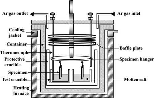
The experimental apparatus is shown in . The Li2O–LiCl molten salt was introduced into a high-density MgO crucible and then heated at 300°C for 3 h in an Ar atmosphere to remove any possible moisture. After heating to 650°C, the specimens were immersed in the Li2O–LiCl salt and kept at 650°C for 168 h. The Li2O concentrations were 1 and 3 wt% which are general range of electrolytic reduction process. Low Li2O concentration below 1 wt% leads to corrosion of Pt anode through the formation of Li2PtO3 or dissolution depending on its concentration [Citation1]. Therefore, Li2O concentration should be below 3 wt% in order to reduce rare earth oxide elements in spent fuel [Citation2]. Following the high-temperature corrosion test, the specimens were withdrawn from the salt and kept in a reactor under Ar atmosphere while the furnace was cooled to room temperature.
Next, the reactor was opened and the specimens were removed and visually examined. Then, they were ultrasonically cleaned in acetone and dried for more than 24 h in a drying oven. Initial and final weights of the specimens exposed to the molten salt were measured to assess the degree of corrosion. The corroded specimens were cut by a diamond cutter, ultrasonically cleaned in acetone for characterization purposes, and prepared for metallographic examination by cold-mounting, grinding, and polishing. The microstructures, morphologies, and chemical compositions of the surfaces and the cross sections were examined using a scanning electron microscope (SEM, JEOL, JSM-6300) equipped with an energy dispersive spectrometer (EDS). X-Ray diffraction (XRD, Rigaku, DMAX/1200) was used to determine the structures of the hot-corrosion products.
3. Results and discussion
3.1. Corrosion rate
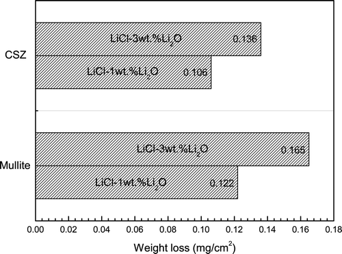
The weight changes of CSZ and mullite specimens after corrosion testing at 650°C in Li2O–LiCl for 168 h are shown in . CSZ exhibited lower corrosion rates than mullite: the weight losses for CSZ and mullite in the case of 3 wt% Li2O increased 28% and 35%, respectively, more than those in the case of 1 wt% Li2O. These weight losses of the ceramic specimens are 1/100–1/30 less value compared to that of commercial nickel-base alloy Inconel 713LC; 14.3mg/cm2 [Citation13] and iron-base alloy Incoloy 800H; 50 mg/cm2 [Citation15], respectively, at 650°C for 168 h with 3 wt% of Li2O. The weight loss of the metallic specimens over time has been attributed to the cracking of the protective layer, leading to spallation from the base metal surface as well as the dissolution of scales and other corroded products [Citation5,Citation16]. Therefore, it was thought that the formation of the corrosion layer and its adherence to the base metal significantly influenced the weight variation of the specimens. In the case of ceramic materials under these electrolytic conditions, the weight loss mechanism was mainly governed by the chemical reaction between the specimen surface and Li2O in molten LiCl and by crack formation due to phase transformation and/or thermal shock. Thus, under these experimental conditions, the weight loss of ceramic materials was not severe when compared to metallic materials, provided catastrophic failure did not occur.
3.2. Corrosion products
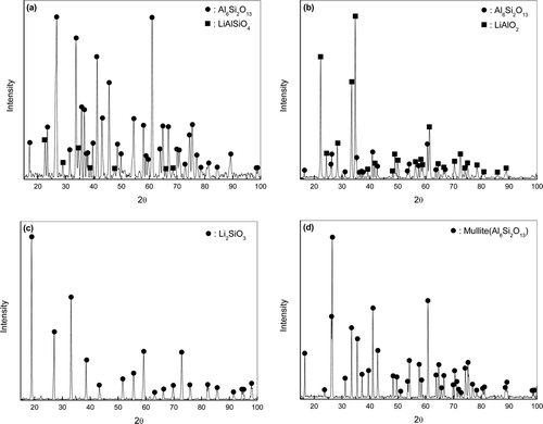
shows the XRD patterns of the surface corrosion layer and corrosion products of mullite corroded at 650°C in (1, 3) wt% Li2O–LiCl for 168 h and the as-received specimen. It was found that LiAlSiO4 and LiAlO2 were formed on the specimen surfaces in addition to the initial mullite phase at Li2O concentrations of 1 and 3 wt%, respectively, ((a) and (b)). Negligible amounts of corrosion products were observed at 1 wt% Li2O, while sufficient Li2SiO3 corrosion product was detected at 3 wt% Li2O after cleaning of the corroded specimens ((c)). It should be noted that the composition of the specimen surface differed with the concentration of Li2O in molten LiCl:LiAlSiO4 was observed at 1 wt% Li2O and LiAlO2 at 3 wt% Li2O. It seems that LiAlSiO4 was formed by the reaction between Li2O and Al6Si2O13 in the initial corrosion reaction. When the Li2O concentration is sufficiently high, Al6Si2O13 would react with Li2O to form Li2SiO3, which is a corrosion product collected after cleaning of corroded specimens. This reaction is thermodynamically favored as calculated by Equation 1 [Citation17].
Figure 3. XRD patterns of the surface corrosion layer of mullite corroded at 650°C for 168 h: (a) in 1 wt% Li2O–LiCl, (b) in 3 wt% Li2O–LiCl, (c) corrosion products in 3 wt% Li2O–LiCl, and (d) the as-received specimen.
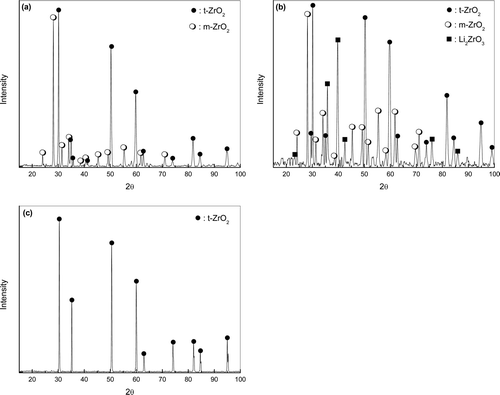
shows the XRD patterns of the surface corrosion layer of CSZ corroded at 650°C in (1, 3) wt% Li2O–LiCl for 168 h and the as-received specimen. No debris was released from the specimen surface regardless of the Li2O concentration in these specimens. The specimen surface was composed of tetragonal ZrO2 as well as monoclinic ZrO2 after the corrosion experiment at 1 wt% Li2O ((a)). With an increase in the concentration of Li2O to 3 wt%, a new Li2ZrO3 phase appeared in addition to t-ZrO2 and m-ZrO2 ((b)). While the as-received CSZ had a tetragonal crystal structure ((c)), all the product crystal structures were partially transformed to monoclinic. Because the tetragonal phase is stabilized by CaO, the presence of the monoclinic phase suggests that CaO was separated from the CSZ phase, and then, that portion of the CaO-depleted zirconia returned to its original monoclinic phase. Furthermore, the formation of Li2ZrO3 is thermodynamically favorable from the reaction between ZrO2 and Li2O, as calculated by Equation 2.
Figure 4. XRD patterns of the surface corrosion layer of CSZ corroded at 650°C for 168 h (a) in 1 wt% Li2O–LiCl, (b) in 3 wt% Li2O–LiCl, and (c) the as-received specimen.
CaO has been reported to have high solubility in molten salt systems, including LiCl [Citation18]. Hence, it could be interpreted that CaO was eluted out of the CSZ phase in molten LiCl, after which the remaining ZrO2 reacted with Li2O to form the Li2ZrO3 phase.
3.3. Corrosion behavior
Cross-sectional SEM images of the mullite and CSZ corroded at 650°C for 168 h in molten (1, 3) wt% Li2O–LiCl were obtained to investigate the morphologies of the surfaces and internal corrosion layers (). Corrosion products formed on the mullite surface and the outermost layers exhibited cracks and partial spallation of corrosion products ((a)). This seems to be because of the difference in the thermal expansion coefficient between mullite matrix and surface corrosion product, which was identified as LiAlSiO4, and thus, the induced stress could be responsible for the spallation [Citation13,Citation16]. In the case of 3 wt% Li2O, the outermost layer was cracked and spalled, and the resultant debris could be collected for XRD analysis. The main reason for the higher mullite corrosion rate at 3 wt% Li2O was formation of cracks on the specimen surface, which increased the reaction surface area and accelerated the corrosion rate as the reaction time progressed.
Figure 5. Cross-sectional SEM images of mullite corroded at 650°C for 168 h (a) in 1 wt% Li2O–LiCl and (b) in 3 wt% Li2O–LiCl and CSZ corroded at 650°C for 168 h (c) in 1 wt% Li2O–LiCl and (d) in 3 wt% Li2O–LiCl.
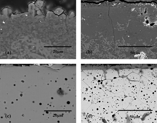
(c) shows the cross section of the CSZ specimen after the corrosion test with 1 wt% Li2O. The morphology of the corroded CSZ was somewhat different from that of mullite, as negligible microcracks were visible on the surface corrosion layer. However, there were signs of spallation, which was caused by the thermal stress induced by phase transformation and by the difference in the thermal expansion coefficient between the matrix and corrosion product [Citation19]. It was clearly observed that the morphology of the specimens changed with the increase in Li2O concentration to 3 wt% for the CSZ specimen ((d)). The corrosion behavior showed typical intergranular corrosion attacking the grain boundary up to a depth of 80 μm. The formation reaction of Li2ZrO3 could accelerate splitting CSZ into its elemental forms and thus generated free CaO became more easily soluble to molten salt. Hence, depletion of CaO at the grain boundary contributed to continuous diffusion of oxygen toward inside of specimen. This kind of corrosion was expected to increase the corrosion rate due to spallation of the corrosion product as a grain according to corrosion time. The formation of Li2ZrO3 as given in Equation 2 would result in lattice mismatch in the matrix, which could also contribute to the acceleration of the corrosion rate.
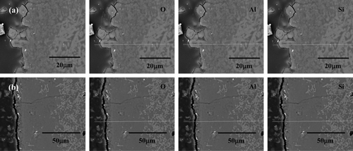
shows the cross-sectional SEM image and the EDS line analysis result of mullite corroded at 650°C for 168 h according to Li2O concentration. In the case of 1 wt% Li2O, the protruded phase of the outermost layer had increasing Si and Al concentrations with increasing depth from the surface ((a)). In contrast to the results in the case of 1 wt% Li2O, the Al concentration in the outermost layer was higher than the Si concentration in the case of 3 wt% Li2O, as shown in (b). This result agreed well with the XRD data, which detected LiAlSiO4 and LiAlO2 as the minor and major phases for 1 wt% Li2O and 3 wt% Li2O, respectively. Since the fraction of the protruded phase in the mullite specimen was relatively small compared to the surface area, the corrosion product debris on the specimen surface after the corrosion experiment was found to be LiAlSiO4.
Figure 6. Cross-sectional microstructures and EDS line analysis results of mullite corroded at 650°C for 168 h in (a) 1 wt% Li2O–LiCl and (b) 3 wt% Li2O–LiCl.
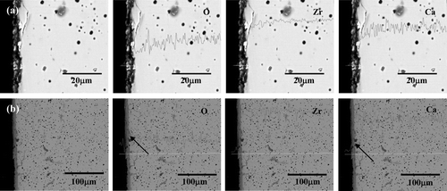
shows the cross-sectional SEM image and the EDS line analysis results for CSZ corroded at 650°C for 168 h according to Li2O concentration. It was clear that the concentrations of Zr, Ca, and O did not change in relation to the corrosion depth at 1 wt% Li2O, as shown in (a), while the Ca concentration was drastically decreased with a sharp increase in O at the surface (indicated with arrows), as shown in (b). From the EDS and XRD results on the CSZ specimen, the surface layer was partially phase-changed in the case of 1 wt% Li2O, while the Li2ZrO3 phase was formed by the reaction between Li2O and ZrO2, as a result of the depletion of CaO through dissolution into molten LiCl.
Figure 7. Cross-sectional microstructures and EDS line analysis results of CSZ corroded at 650°C for 168 h in (a) 1 wt% Li2O–LiCl and (b) 3 wt% Li2O–LiCl.
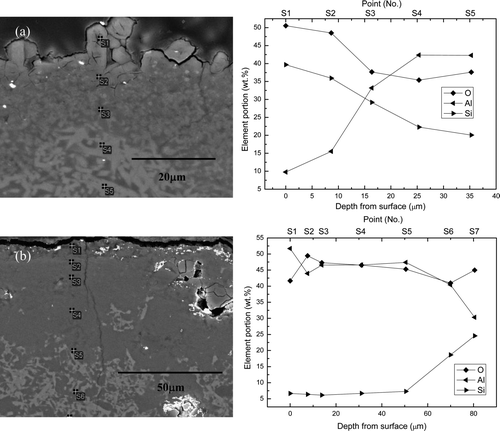
In order to more closely examine the compositional variation, the chemical composition of the corroded area was measured according to the distance from the surface. shows the cross-sectional SEM image and the EDS point quantitative analysis results for mullite corroded at 650°C for 168 h for the different Li2O concentrations. The outermost corrosion layer, especially the protruded product, had a completely different chemical composition (39.65 wt% Si, 9.78 wt% Al) as indicated by “S1” in (a), which agreed well with (a). The Al concentration gradually increased as the depth from the surface increased, and it was finally balanced. It should be noted that the equilibrium concentration point was “S4,” which indicates that the total attack depth of the mullite specimen in 1 wt% Li2O–LiCl molten salt was 31 μm. For the mullite specimen corroded in 3 wt% Li2O–LiCl molten salt, the Al concentration was found to be higher than Si, as can be seen at “S1–S5” (51.7–47.39 wt% Al, 6.64–7.27 wt% Si) in (b). This data also agreed with (b), and the total attack depth was 83 μm.
Figure 8. Cross-sectional microstructures and EDS analysis results of mullite corroded at 650°C for 168 h in (a) 1 wt% Li2O–LiCl and (b) 3 wt% Li2O–LiCl.
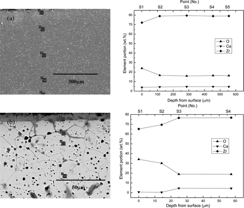
In the case of CSZ corroded at 1 wt% Li2O concentration, the EDS point analysis result in (a) showed that the Zr elemental concentration at S1 was 72.5 wt%. The normal concentration of Zr in CSZ with 5.5 wt% CaO should be 74 wt%, so slight decrease of Zr and Ca concentrations at the surface layer indicates the formation of Li2ZrO3 in addition to monoclinic ZrO2 even though Li2ZrO3 was not detected by XRD due to the small fraction. The composition of each element returned to normal after point S2, which means that the total attack depth was 25 μm. The elemental distribution of CSZ after the corrosion test in 3 wt% Li2O was completely changed, as shown in (b). The noticeable differences were the high O and low Ca concentrations at S1 in (b); these values, as well as the Zr concentration, returned to normal after the point S3. Hence, the total attack depth increased to 28 μm as the Li2O concentration increased to 3 wt%.
Figure 9. Cross-sectional microstructures and EDS analysis results of CSZ corroded at 650°C for 168 h in (a) 1 wt% Li2O–LiCl and (b) 3 wt% Li2O–LiCl.
The comparison of the experimental results for mullite and CSZ show that mullite had a thicker corrosion layer than CSZ mainly because the higher reactivity between mullite and Li2O easily generated Li2SiO3 in molten LiCl. Even though the reactivity of CSZ to Li2O was relatively lower than mullite, it formed Li2ZrO3 after the separation of the CaO stabilizer from the CSZ lattice due to the high solubility of CaO in molten LiCl. This dissolution seems to accelerate the corrosion reaction due to the formation of cracks caused by the volume mismatch between the matrix and corrosion products. This result indicates that ceramic materials such as mullite and CSZ are chemically more favorable for a structural part in an electrolytic reduction process of spent nuclear fuel than metallic materials. However, the drawbacks in using these ceramic materials are that mechanical impact should be moderately restricted and the concentration of Li2O should be controlled to as low as possible to suppress the corrosion rate.
4. Conclusion
The corrosion behaviors of mullite and CSZ were investigated in a high-temperature corrosion environment. The conclusions were as follows:
| 1. | The corrosion rate of CSZ was lower than mullite: the weight losses for CSZ and mullite increased 28% and 35%, respectively, as the Li2O concentration increased from 1 to 3 wt%. The total attack depth of CSZ increased slightly, from 25 to 28 μm, with Li2O concentration increasing from 1 to 3 wt%, whereas the depth for mullite increased dramatically, from 31 to 83 μm, with the increase in Li2O concentration. The severe corrosion of mullite at 3 wt% Li2O was mainly attributed to crack formation, facilitating internal migration of molten salt and thus increasing the reaction surface area. In contrast to the mullite results, the slight increase of attack depth for CSZ at 3 wt% Li2O was due to the progression of corrosion through the grain boundary. | ||||
| 2. | Corrosion products, such as LiAlSiO4 and LiAlO2, were formed on the mullite specimen surface at 1 and 3 wt% Li2O, respectively, and it was found that the debris released was Li2SiO3. The surface of CSZ was composed of t-ZrO2 as well as m-ZrO2 after the corrosion test at 1 wt% Li2O, and the Li2ZrO3 phase appeared in addition to t-ZrO2 and m-ZrO2 at 3 wt% Li2O. | ||||
| 3. | For applying ceramic materials such as mullite and CSZ to electrolytic reduction processes, the Li2O concentration should be kept as low as possible, desirably below 1 wt%. However, the concentration range of Li2O should be between 1 and 2 wt% taking into account of electrolytic reduction rate. Cracking and spallation should be also considered for long-term use under a thermal cyclic environment. | ||||
Acknowledgement
This work was funded by the National Mid- and Long-term Atomic Energy R&D Program, supported by the Ministry of Education, Science and Technology of Korea.
References
- Lee , H.S. , Park , G.I. , Kang , K.H. , Hur , J.M. , Kim , J.G. , Ahn , D.H. , Cho , Y.Z. and Kim , E.H. 2011 . Pyroprocessing Technology Development in KAERI . Nucl. Eng. Tech , 43 : 317–328
- Yoo , J.H. , Seo , C.S. , Kim , E.H. and Lee , H.S. 2008 . A Conceptual Study of Pyroprocessing for Recovering Actinides from Spent Oxide Fuels . Nucl. Eng. Tech , 40 : 581–592
- Indacochea , J.E. , Smith , J.L. , Litko , K.R. , Karell , E.J. and Raraz , A.G. 2001 . High-Temperature Oxidation and Corrosion of Structural Materials in Molten Chlorides . Oxid. Met , 55 : 1–16
- Karell , E.J. , Gourishankar , K.V. , Smith , J.L. , Chow , L.S. and Redey , L. 2001 . Separation of Actinides from LWR Spent Fuel Using Molten-Salt-Based Electrochemical Processes . Nucl. Tech , 136 : 342–353
- Shankar , A.R. , Mudali , U.K. , Sole , R. , Khatak , H.S. and Raj , B. 2008 . Plasma-sprayed yttria-stabilized zirconia coatings on type 316L stainless steel for pyrochemical reprocessing plant . J. Nucl. Mater , 372 : 226–232
- Indacochea , J.E. , Smith , J.L. , Litko , K.R. and Karell , E.J. 1999 . Corrosion performance of ferrous and refractory metals in molten salts under reducing conditions . J. Mater. Res , 14 : 1990–1995
- Mohanty , B.P. and Shores , D.A. 2004 . Role of chlorides in hot corrosion of a cast Fe-Cr-Ni alloy. Part I: Experimental studies . Corros. Sci , 46 : 2893–2907
- Ruh , A. and Spiegel , M. 2006 . Thermodynamic and kinetic consideration on the corrosion of Fe, Ni and Cr beneath a molten KCl-ZnCl2 mixture . Corros. Sci , 48 : 679–695
- Tzvetkoff , Tz. and Kolchakov , J. 2004 . Mechanism of growth, composition and structure of oxide films formed on ferrous alloys in molten salt electrolytes-a review . Mater. Chem. Phys , 87 : 201–211
- Ishitsuka , T. and Nose , K. 2002 . Stability of protective oxide films in waste incineration environment-Solubility measurement oxides in molten chlorides . Corros. Sci , 44 : 247–263
- Colom , F. and Bodalo , A. 1972 . Corrosion of Iron (ARMCO) in KCl-LiCl Melts . Corros. Sci , 12 : 731–738
- Cho , S.H. , Seo , C.S. , Yoon , G.S. , Park , H.S. and Park , S.W. 2006 . Corrosion Behavior of Haynes Alloys in Lithium Molten Salt under Oxidizing Atmosphere . J. Kor. Inst. Met. & Mater , 44 : 707–713
- Cho , S.H. , Kang , D.S. , Hong , S.S. , Hur , H.J. and Lee , H.S. 2008 . Corrosion Behavior of Ni-Base Superalloys in a Hot Molten Salt . J. Kor. Inst. Met. & Mater , 46 : 577–584
- Takeuchi , M. , Kato , T. , Hanada , K. , Koizumi , T. and Aose , S. 2005 . Corrosion resistance of ceramic materials in pyrochemical reprocessing condition by using molten salt for spent nuclear oxide fuel . J. Phys. Chem. Solids , 66 : 521–525
- Cho , S.H. , Seo , C.S. , Yoon , J.S. , Lee , H.S. and Park , S.W. 2007 . Corrosion Behavior of Superalloys in a Hot Lithium Molten Salt . J. Ind. Eng. Chem , 13 : 729–734
- Wood , G.C. and Stott , F.H. 1987 . Oxidation of alloys . Mater. Sci. Tech , 3 : 519–530
- 2007 . HSC Chemistry 6.1 , Pori , , Finland : Outotec Research Oy .
- Wang , S. , Zhang , F. , Liu , X. and Zhang , L. 2008 . CaO solubility and activity coefficient in molten salts CaCl2–x (x=0, NaCl, KCl, SrCl2, BaCl2 and LiCl) . Thermochim. Acta , 470 : 105–107
- Wu , B.C. and Chang, D. Tu and S.L. Wang , E. 1989 . Microstructures, Properties and Failure Analysis of (ZrO2-8wt.%Y2O3)/((Co,Ni)-Cr-Al-Y) Thermal Barrier Coatings . Mater. Sci. Eng , A 111 : 201–210
