Abstract
The thermoelastic analyses of cladding for lead–bismuth cooled accelerator-driven system (ADS) are conducted for the beam transients. The beam transients are considered to be caused by the abnormal behavior of the accelerator and are peculiar to ADS. The program of the thermoelastic analyses is developed for the evaluation of the stresses of the cladding. This program is intended to analyze a fuel pin of a cylindrical model, and solves the thermoelastic problem by the use of the finite-element-method. The beam transients are analyzed by employing the ADS dynamic calculation code and the program of the thermoelastic analyses for the ADS designed by Japan Atomic Energy Agency. As a result, the transformation of the beam shape does not cause the cladding failure. However, the ductile failure is caused by the beam incident position change in several seconds. These results are also compared with those of the creep analyses conducted in the previous study, and both the creep and the ductile failure are revealed to be caused by the beam incident position change. Consequently, the beam incident position change is concluded to have a high risk of cladding failure.
1. Introduction
Accelerator-driven system (ADS) has been investigated for the reduction of high level radioactive wastes by transmuting the minor actinides (MAs) and long-lived fission products [1,2]. The ADS is an innovative reactor and consists of a high-intensity proton accelerator, a subcritical core, and a spallation target. The ADS has a high safety margin since ADS employs a subcritical core. In addition, a large amount of MA can be loaded and transmuted because the flexibility of fuel loading is very high in the core. There are many topics to establish the technology of ADS, but the studies of the ADS dynamics are very few because of the lack of the dedicated computational code for the ADS dynamics. In particular, the beam transients are peculiar to ADS but have not been investigated. The beam transients are defined as the beam profile changes in normal beam power and cooling condition in this article. For the investigation of the beam transient, the ADS dynamic calculation code ADSE had been developed [3]. The ADSE can obtain a dynamic change of the distributions of the neutron flux, the thermal power, and the temperatures of fuel, cladding, and coolant. In addition, the cladding failure analysis program for creep was developed by introducing the method of the cumulative creep damage fraction (CDF) calculation, and various beam transients were analyzed in the previous study [4]. However, the failure caused by the instantaneous large load, such as a ductile failure, has not been investigated, and therefore, should be analyzed for the safety of ADS.
In this study, the program of the thermoelastic analyses was developed and the beam transients were analyzed from the viewpoint of a ductile failure of a cladding. In Section 2, the program for the thermoelastic analyses was developed for analyzing a ductile failure of claddings, and the validation of the program was carried out by the comparison with the result of the transient analyses of the sodium-cooled fast-breeder reactor. In Section 3, the thermoelastic analyses on the beam transients of lead–bismuth cooled ADS were conducted, and the results of the analyses were compared with those of the creep analyses in the previous study. This study was summarized in Section 4.
2. Development of program of thermoelastic analyses
2.1. Development of program
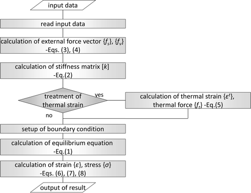
The state of the stresses in a transient should be analyzed for the prevention of the failures of fuel pins. The stress analyses with solving theoretical formulae are one of the analytical methods, but this method is difficult to follow the time-dependent changes, since some parameters such as the inner pressure of claddings are varied in a transient. The computational program is desirable for the analyses of the time variation, and the program of the thermoelastic analyses was developed with the use of the finite-element-method in this study. This program is intended to analyze a fuel pin. As a calculation model, an axisymmetric cylinder was used and the object is divided into the eight-node rectangular isoparametric elements. The following equilibrium equation is solved in the program [5]:
2.2. Validation of program
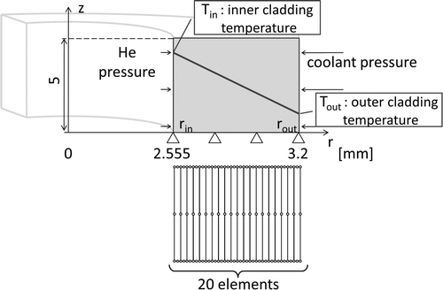
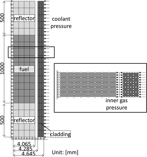
This program was validated by the comparison with the results of the transient analyses of the loss-of-flow accident for the sodium-cooled fast-breeder reactor [6]. The coolant pumps slowly stopped and the control rods automatically and gradually fell down in the core in the transient. The static distributions of stresses and the distributions of the von Mises stress in the transient were compared. These comparisons are effective for the validation because the calculation capability of the statics and dynamics is expected to be confirmed. The time variation of the temperatures after the coolant pump trip is shown in . The initial inner cladding temperature was 620°C and outer onewas 585°C. The cladding model employed in the calculation was divided into 1 × 20 elements and the lower end of the element was fixed as shown in . The material properties were based on the temperature conditions at each node. The parameters of fuel pin and the external forces acting on the fuel pin are given in .
Table 1. Fuel pin parameters in validation of the program of the thermoelastic analyses.
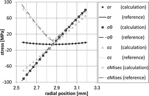
The circumferential, radial, axial, and von Misesstresses of a cladding (σθ, σr, σz, and σMises, respectively) at the steady state were compared as shown in . The calculation results of circumferential and radial stresses were well agreed with reference data, but that of the axial stress differed by up to 16%. This difference was considered to be derived from the setup of axial boundary condition. The large difference was also seen in the von Mises stress around the center of the cladding and it was about 10%. It was because the values of the stresses around the center were small compared to the other part, and therefore, the ratio between the calculation and the reference data became relatively large. Meanwhile, the von Mises stresses at neighborhood of the both surface were agreed within 2%. Considering the erratic reading of the reference data and the differences of the material properties between the calculation and the reference data, the calculation results were considered reasonable.
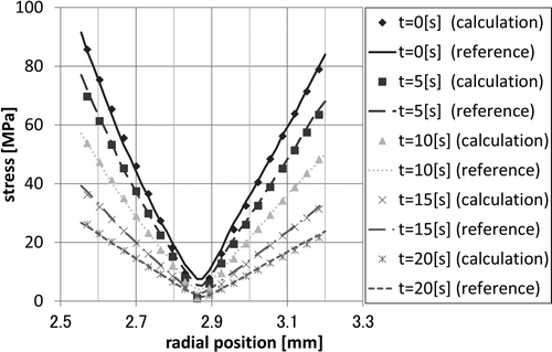
The results of von Mises stress in the transient are presented in . The von Mises stresses at each time steps were well agreed within 5% except for around the middle of the cladding. The ratio between the calculation and the reference around the middle of the cladding was above 15%. As mentioned above, the stresses around the center were smaller than those of other parts of the cladding, and these small values were considered to lead to the differences around the center. The calculation in the transient was also executed well in view of the difference of the material properties and the erratic reading.
These comparisons showed that the program of the thermoelastic analyses was proved to have a proper calculation capability in the statics and dynamics. A cladding failure was evaluated by this program in the next section.
3. Thermoelastic analyses of cladding on beam transient
3.1. ADS model and outline of transient analyses
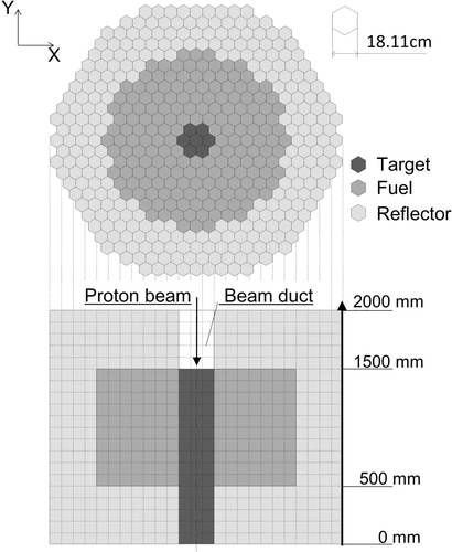
The ADS model employed in this study is the one proposed by Japan Atomic Energy Agency (JAEA) [7,8]. shows the conceptual design of ADS core. The fuel is (MA + Pu)N + ZrN, and lead–bismuth eutectic is used as a coolant and a spallation target. The thermal power of this system is 800 MW and the effective multiplication factor k eff is set to be 0.95. Detailed core parameters are summarized in . As for the plenum length, the upper one was set to 1.2 m and the lower one was 0.5 m.
Table 2. Main parameters of the ADS model in the analyses.
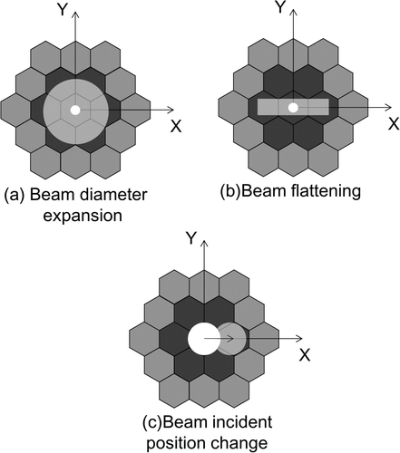
The beam transients were considered to be caused by the troubles of the magnets for the beam expansion, the focus, and the bending. These troubles of the magnets lead to the change of a beam shape and a beam incident position. Beam diameter expansion, beam flattening, and beam incident position change were analyzed as a beam transient in this section. shows the schematics of the beam transients. The beam shape and position in this study were assumed to be varied inside the spallation target instantaneously. In addition, the beam distribution was assumed to be uniform to consider the severe condition, since the influence of the edge of the uniform beam was larger than that of the practical Gaussian beam distribution especially in the case that beam edge got closer to the fuel assembly.
The transients were analyzed by ADSE and the program of the thermoelastic analyses. The fuel pin model employed in the program of the thermoelastic analyses is shown in . The calculation meshes at the axial direction were divided into 20 meshes in ADSE, and moreover, this mesh was subdivided into five meshes at the axial direction, four meshes for fuel, and three meshes for cladding at the radial direction in the program of the thermoelastic analyses. The gap between a fuel pellet and a cladding was assumed to be remained at the same size. The amount of gas in a fuel pin was set to be 0.05457 mol/pin. This amount was equivalent to the state of end-of-cycle. The release rateof a fission gas was set to be 100% to assume the severe condition. The inner gas pressure was assumed to be identical at the whole position of the inner surface. Considering these conditions, the initial inner pressure became 3.46 MPa. The inner pressure was varied in response to the coolant temperature change.
The cladding failure was assumed to occur if the von Mises stress of the node with the maximum temperature exceeded the failure criterion of the yield stress or the 0.2% proof stress. The maximum temperature node was selected as the failure assessment node, since a material degradation was supposed to be the most rapid. The yield stress means the elastic limit, and the 0.2% proof stress is equivalent to the yield stress of the material which does not show a yield point. This criterion was very severe as compared to the real condition, but effective to consider the analyses on the safe side because a plastic deformation is considered to decrease the safety of the core by causing some sort of troubles such as a change of flow channel. The yield stress and 0.2% proof stress are the substance-specific characteristics. They were calculated with the use of the temperature correlation formula on the basis of the experimental data [9,10]. The minimum values in the experiments were employed as the criteria. The strain rate in the data of the 0.2% proof stress was from 0.3%/min to 600%/min. Since the data of the yield stress are in the range between 20 and 600°C, and those of the 0.2% proof stress are in the range between 700°C and 1200°C, the temperature extrapolations of the experimental data were employed between 600°C and 700°C, and the lower value between the yield stress and the 0.2% proof stress was employed.
3.2. Results of thermoelastic analyses on beam transient
3.2.1. Beam diameter expansion
Beam diameter expansion is the possible event when some beam focus magnets become an abnormal state. The initial beam diameter was set to be 1 cm. Although this value was very severe because the small diameter beam generates the strong local power peak and has very high risk to cause the damage on the beam window, this initial diameter was adopted to consider the influence of the beam expansion severely. The diameter at the transient was expanded up to 40 cm. This value is largest in view of the size of the target. The heat on the beam window was not evaluated in the analyses.
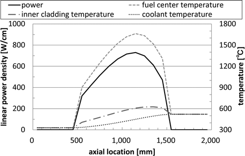
and show the distributions of the linear power density and the temperatures of the fuel pin with severest conditions at the initial state and the case of 40-cm diameter expansion, respectively. The maximum temperature was seen at the position of 1400 mm, and the cladding failure was evaluated with this position. The maximum temperatures, the von Mises stress, the yield stress, and the 0.2% proof stress after beam diameter expansion are summarized in . Themaximum strain rate was 3.5%/min in this transient, and the 0.2% proof stress was available. The lower value between the extrapolation of the yield stress and the 0.2% proof stress was applied as a criterion since the initial cladding temperature was 626.0°C. The cladding temperatures were increased at all analyses, and the temperature rise was larger, as the diameter became larger because the spallation source became closer to fuel assemblies by the beam diameter expansion, and the flux was increased. In fact, the flux at each fuel assemblies at 40-cm diameter beam was about 1–4% large compared to that at initial state, and the linear power density at the failure assessment node was also increased by about 9% with 40-cm diameter beam. The increase of the flux also affected the von Mises stresses. Therefore, the biggest changes were seen at 40-cm diameter beam since the beam was closest in the transient. The maximum cladding temperature increased to 642.0°C, and the von Mises stress was 51.4 MPa. This value was much smaller than the failure criterion of the yield stress, 213.9 MPa. There were no ductile failures by beam diameter expansion.
Table 3. Variations of maximum cladding temperature, von Mises stress, yield stress, and 0.2% proof stress on beam diameter expansion.
3.2.2. Beam flattening
Beam flattening was also caused by the extraordinary state of the focus magnets. The initial beam diameter was set to be 1 cm and a rectangular beam was employed as a flattened beam. The X-direction and the Y-direction of the beam in this transient are defined in . The X-direction width of the beam was fixed at 40 cm and the Y-direction width was changed from 1 cm up to 20 cm to examine the effect of the size of the beam.
The temperatures and the von Mises stress of cladding after beam flattening exceeded those of the initial state, and the largest temperature change occurred in the case of 40 cm × 20 cm rectangular beam as described in . The distributions of the linear power density and the temperatures at 40 cm × 20 cm rectangular beam are presented in . The approach of the beam toward the fuel assemblies caused these increases as the same as beam diameter expansion, since the flux was increased by about 3–5% at each fuel assemblies. In addition, the linear power density at the severest assembly increased by about 2–9% and the temperature rise was up to 13.4°C. The maximum von Mises stress was 51.8 MPa, and did not exceed the failure criterion. Therefore, the ductile failure was not caused by beam flattening. As for the change of the Y-direction width, there were very slightdifferences in the temperatures and the stresses. Theresults indicated that the change of the Y-direction width did not have much influence on the temperatures and the stress.
Figure 10. The distributions of linear power density and temperatures at the case of 40-cm diameter beam.
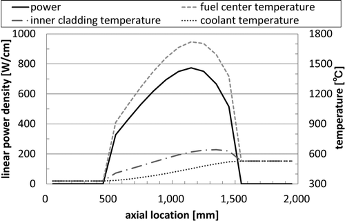
Figure 11. The distributions of linear power density and temperatures at the case of 40 cm × 20 cm rectangular beam.
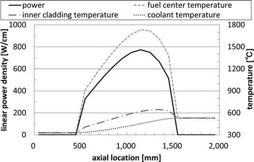
Table 4. Variations of maximum cladding temperature, von Mises stress, yield stress and 0.2% proof stress on beam flattening of 40-cm X-direction width rectangular beam.
3.2.3. Beam incident position change
Beam incident position change is caused by the malfunction of some bending magnets. The initial beam diameter was set to be 1 cm, 10 cm, 20 cm, and 30 cm in this transient to study the case with the different diameter cases. This analysis enables to obtain the knowledge of the composite transient like both the bending and the focus magnets become unusual conditions at the same time. The move distances of the center of the each beam diameter were determined to be in the range of the target.
The calculation results of the maximum cladding temperatures, the von Mises stresses, and the failure criteria are shown in . The maximum strain rate was 63.6%/min, and the failure criterion of the 0.2% proof stress was also available. The cladding temperatures and the von Mises stresses were increased remarkably, as the beam became closer to the fuel assembly. The beam transfer made the movement of the spallation flux peak, and resulted in such extreme changes. For example, the flux at the closest assembly to the beam increased by 72% in the case of 25-cm movement of 1-cm diameter beam. The larger move distance made the claddings at severer conditions in the cases of all diameters. The case of 15-cm movement of 20-cm diameter beam was severest. In , the distributions of the linear power density and the temperatures at this case were plotted. The linear power density was almost doubled at the location of 1350 mm and the maximum cladding temperature reached to 890.4°C. shows the time variations of the cladding temperature and the stresses, and shows the variation of the inner pressure. The yield stress exceeded the failure criterion at 9.1 s. From these results, beam incident position change was revealed to cause the rapid change andlead to the ductile failure of the cladding in a short time.
Figure 12. The distributions of linear power density and temperatures at 15-cm movement of 20-cm diameter beam.
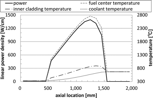
Figure 13. Time variation of cladding temperature and stresses on beam incident position change of 15-cm movement of 20-cm diameter beam.
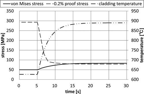
Figure 14. Inner pressure variation on beam incident position change of 15-cm movement of 20-cm diameter beam.
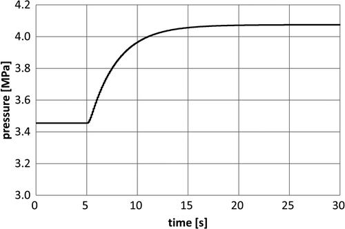
Table 5. Variations of maximum cladding temperature, von Mises stress and failure criterion on beam incident position change.
3.3. Comparison between creep and thermoelastic analyses
The creep rupture analyses on beam transients were performed in [4]. The beam transients of beam diameter expansion, beam flattening, beam hollowing, and beam incident position change were analyzed with the use of ADSE and the creep analysis program under the same calculation geometry. In the creep analyses, cumulative CDF was used as the evaluation index of the failure, and the failure was determined when CDF exceeded the failure criterion of 0.5 within the time interval of 1000 s.
This section compared the results of both the creep and the thermoelastic analyses in beam diameter expansion, beam flattening, and beam incident position change, and then, discussed what transients should be considered as having a high risk for the failure from the viewpoint of both the creep and the ductile failures.
3.3.1. Beam diameter expansion
The 40-cm diameter beam was the severest case in beam diameter expansion at both analyses. The maximum CDF value after 1000 s was 1.30 × 10⁻⁵ in the creep analyses, and the von Mises stress was 51.4 MPa in the thermoelastic analyses. They are quite small values compared to each failure criteria. Therefore, the failure risk by beam diameter expansion is very small.
3.3.2. Beam flattening
The CDF value and the von Mises stress showed the largest values in the case of the 40 cm × 20 cm rectangular beam. The maximum CDF value reached into 1.80 × 10⁻⁵ but fell below 0.5. The von Mises stress was also under the yield stress of the failure criterion. Hence, both cladding failures on beam flattening are impossible.
3.3.3. Beam incident position change
The results of CDF values on every case of the creep analyses are summarized in . Some CDF values exceeded the criterion in the cases of over 15-cm movement with 1-cm diameter beam, over 15-cm movement with 10-cm diameter and over 10-cm movement with 20-cm diameter. The rupture time became shorter, as the move distance was larger. For example of the cases of 1-cm diameter beam, it was about 800 s at 15-cm movement and 9.0 s at 25-cm movement. The rupture time at the severest case of 15-cm movement of 20-cm diameter beam was 6.1 s. As for the thermoelastic analyses, the von Mises stress exceeded only in the case of 15-cm movement of 20-cm diameter beam and the rupture time was 9.1 s. The rupture time by creep was short compared to the time by the ductile failure at the case of 15-cm movement of 20-cm diameter beam. The creep failure was impossible to precede the ductile failure, and therefore, the failure mode at this case was considered the ductile failure. The precedence of the creep rupture time was considered to come from the strict value of the safety factor in the CDF calculation. As for the other case of causing a failure, the failure mode was the creep, and the rupture times were longer than the time by a ductile failure. Accordingly, beam incident position change causes the cladding failure even if the failure mode is the creep or the ductile failure, and should be taken into account as one of the severe transients.
Table 6. CDF value by creep analyses on beam incident position change [4].
For the prevention of the cladding failures, some modifications in the design should be done. The review of the core design was conducted for the creep in previous study [4]. For example, the prolongation of the plenum length, the use of other cladding materials, and the change of fuel composition were discussed. The application of these modifications should be determined with consideration of the results not only of the creep analyses but also of the thermoelastic analyses.
4. Conclusion
The thermoelastic analyses of the cladding on the beam transient of the lead–bismuth cooled ADS were conducted. The program of the thermoelastic analyses was developed and validated by comparing the results of the transient of the sodium-cooled fast-breeder reactor.
The beam transient analyses were conducted for the ADS designed by JAEA with the combined use of ADSE and the program of the thermoelastic analyses. Beam diameter expansion and beam flattening showed a little temperature increase, and the von Mises stress did not exceed the failure criterion of the yield stress. Meanwhile, beam incident position change caused the great temperature increases, and led to the rapid increase of the von Mises stresses. These rapid variations were more noticeable as the move distance was bigger, and the ductile failure of the cladding was caused in the case of 15-cm movement of 20-cm diameter beam.
Compared to the creep analyses conducted in the previous study, it was found that beam diameter expansion and beam flattening did not cause the ductile and the creep failures. However, the cladding failed on beam incident position change at both analyses. Especially, the ductile failure was occurred in several seconds, while the creep rupture times were from several tens of seconds to several tens of minutes at the time interval of these analyses. The creep rupture was also possible in the case that the move distance wassmall and the ductile failure was not caused. It was concluded that beam incident position change had a high risk to cause the cladding failure. Therefore, some modifications in the design should be considered to prevent the cladding failures, and the applications of them should be decided from the viewpoint of both the analysis results of the creep and the thermoelastic.
References
- Tsujimoto , K. , Sasa , T. , Nishihara , K. , Takizuka , T. and Takano , H. 2000 . Accelerator-driven system for transmutation of high-level waste . Prog. Nucl. Energy , 37 : 339 – 344 .
- Cinotti , L. , Giraud , B. and Abderrahim , H.A. 2004 . The experimental accelerator driven system (XADS) designs in the EURATOM 5th framework programme . J. Nucl. Mater , 335 : 148 – 155 .
- Suzuki , M. , Iwasaki , T. , Aizawa , N. , Sato , T. and Sugawara , T. Development of Advanced Dynamic Calculation Code for Accelerator Driven System . Proc. of Int. Topical Meeting on Nuclear Research Applications and Utilization of Accelerators . May 4–8 2009 . Vienna , , Austria ISBN 978-92-0-150410-4 [CD-ROM]
- Aizawa , N. and Iwasaki , T. 2011 . An analysis of cladding failure on beam transient of lead–bismuth cooled accelerator-driven system . J. Nucl. Sci. Technol , 48 : 892 – 901 .
- Shimoseki , M. and Fujinuma , H. 1988 . Finite-element-method/nonstationary Thermal Stress Programming [in Japanese] , 13 – 23 . Tokyo : Nikkan Kogyo Shimbun Ltd . ISBN 4-526-02350-7
- Lorenzini , E. , Spiga , M. and Corticelli , M.A. 1985 . Accident analysis in LMFBR fuel rods by the FENHT code . Ann. Nucl. Energy , 12 : 91 – 95 .
- Takizuka , T. , Tsujimoto , K. , Sasa , T. , Nishihara , K. and Takano , H. 2002 . Design study of lead–bismuth cooled ADS dedicated to nuclear waste transmutation . Prog. Nucl. Energy , 40 : 505 – 512 .
- Nishihara , K. , Iwasaki , T. and Udagawa , Y. 2003 . A new static and dynamic one-point equation and analytic and numerical calculations for a subcritical system . J. Nucl. Sci. Technol , 40 : 481 – 492 .
- The Japan Welding Engineering Society Atomic Energy Research Committee FME Subcommittee . For cornerstone of future energy – Toward practical use of new materials of fast reactor , [in Japanese], JWES-AE-9907, The Japan Welding Engineering Society, 1999
- Kato , S. , Yoshida , E. and K. Aoto, Ultra-high temperature strength properties on Mod.9Cr–1Mo steel [in Japanese] , JNC TN9400 2000-42, Japan Nuclear Cycle Development Institute, 2000 .
![Figure 2. Temperature variations on transients [6].](/cms/asset/a57e6e44-fd5b-4a64-9894-d6cd7e2d6552/tnst_a_712480_o_f0002g.gif)
