Abstract
In order to realize the planned deuterium plasma experiments using the Large Helical Device, the National Institute for Fusion Science (NIFS) is planning to install a system for tritium recovery from exhaust gas. While adopting typical tritium recovery systems, NIFS has also made plans for the development of a compact reduced-waste recovery system by applying a membrane type dehumidifier. A commercially available membrane dehumidifier was evaluated experimentally for this purpose with the results indicating that such a membrane is feasible for practical application. A small-scale test apparatus having a capacity 1/10 (30 m3(NTP)/h) that of the actual tritium recovery system with the same flow control system was evaluated under actual operating conditions, and the necessary performance for design and operation of the actual system was elucidated.
1. Introduction
Deuterium plasma experiments are currently being planned for the Large Helical Device (LHD) at the National Institute for Fusion Science (NIFS), following the hydrogen plasma experiments presently being conducted. The tritium generated in these experiments (maximum of 55.5 GBq (1.5 Ci)/year) must be recovered before emission, with the annual environmental emission specified at less than 3.7 GBq (0.1 Ci). In order to meet the requirement, NIFS is planning to install a detritiation system having a tritium recovery rate of more than 95%.
Among atmosphere detritiation systems, methods which collect gaseous tritium as tritiated water using the combined processes of catalytic oxidation and adsorption have been widely applied worldwide. To develop more compact and cost-effective systems, alternatives to the adsorption process have also been studied, such as the application of gas separation membranes [Citation1–Citation8].
In a membrane dryer, to obtain the most efficient separation of water vapor, it is desirable to combine pressurizing operation at the feed side with vacuum exhaust operation at the permeate side. However, it is difficult to control the purge gas flow rate while applying vacuum exhaust operation at the permeate side. In the present application, the tritium concentration in the feed gas is low enough to neglect tritium leakage under high-pressure operation. As such, we have combined pressurizing operation at the feed side with atmosphere operation at the permeate side.
At NIFS, a commercially available membrane dehumidifier has been experimentally evaluated for use with the LHD detritiation system under the following conditions [Citation9,Citation10].
| 1. | The permeate side is operated under atmospheric pressure. | ||||
| 2. | The dry bleed gas is purged to the permeate side with variable flow rates. | ||||
| 3. | The target dew point is less than −60°C, which is almost equivalent to the performance of a molecular sieves (MSs) dryer bed. | ||||
As the next step, we have carried out the basic design of an actual tritium recovery system having a treatment capacity of 300 m3(NTP)/h and a tritium recovery rate (defined as the recovery ratio of exit/entrance moisture concentrations of the tritium recovery system) of more than 95% [Citation11]. In this system, the wet outlet air (purge gas) of the membrane dehumidifier is returned to the inlet of the feed pump and dehydrated under compressed conditions. The key element of the tritium recovery system is continuous recycling of the wet purge gas between the membrane dehumidifier and the feed pump under various flow conditions.
To test the design, we have recently constructed a small test apparatus having a capacity 1/10 (30 m3(NTP)/h) that of the actual tritium recovery system with the same flow control system. It was demonstrated that the test system could successfully perform the dual functions of continuous collection of moisture through condensation and control of the dew point in air within −60 to −80°C [Citation12].
The purpose of the present research is to understand in detail the dehumidification characteristics of the polymer membrane module under actual operating conditions. Furthermore, the optimal method of adjusting the purge gas flow rate is examined to reflect the final manufacture specifications, particularly those required for operation and control of the tritium recovery system for the LHD.
2. Experiment
2.1. Experimental device
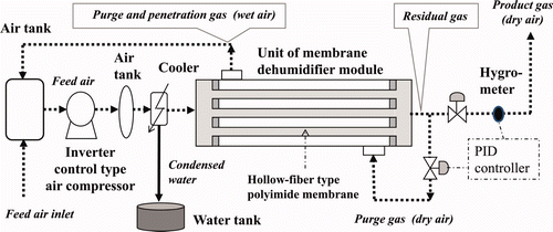
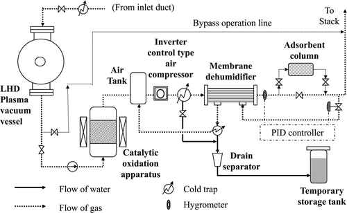
To evaluate the dehumidifier system, we constructed a small-scale test apparatus having a capacity 1/10 (30 m3(NTP)/h) that of the actual tritium recovery system with the same flow control system [Citation12]. The test apparatus was applied to the present experiments without further modifications. The composition and system flow of the test apparatus are shown in . In the apparatus, a commercially available polyimide hollow-fiber module (Ube Industries, UM-C10, OD 90 mm, H 1110 mm) is used. According to the catalogue, this module has a treatment capacity of up to 90 m3(NTP)/h at a feed pressure of 0.7 MPa(G), producing dry air with a dew point of −17°C.
2.2. Experimental conditions
In the actual tritium removal system, the plan is to process exhaust air from the Green House, in which various maintenance procedures on contaminated apparatus or parts are carried out, in addition to purging air from the LHD vacuum vessel. The exhaust air flow rate from the Green House varies according to the operational status of the House.
As a measure of the operating conditions, it was assumed that the processing gas (total feed gas) flow rate may fluctuate between 200 and 300 m3(NTP)/h over short periods. In order to evaluate the system characteristics when the processing gas flow rate is changed, two control methods, purge rate PID (Proportional-Integral-Derivative) control and fixed purge ratio operation, were evaluated experimentally. The operating conditions for the actual removal system and the test apparatus are compared in .
Table 1. Operating conditions.
The tritium recovery rate of the actual recovery system is planned to exceed 95%. If the moisture concentration of the processing gas at the entrance to the system is assumed to be 10,000 ppm (atmospheric-pressure dew point: 7°C, room temperature relative humidity: 35.6%), then a concentration of below 500 ppm (atmospheric-pressure dew point: −27°C) is required at the removal system exit. However, in actual operation it is supposed that more dry air would be generated, depending on the operating conditions of the LHD.
As such, in the present experiments, a moisture recovery equivalent to a MS adsorption tower was adopted. Under high-pressure operation at 0.7 and 0.8 MPa(G), dehumidification to a target dew point of −70°C (moisture concentration: 2.6 ppm) was adopted at the polymer membrane module exit, and under low pressure operation at 0.6 MPa(G), dehumidification to a target dew point of −60°C (moisture concentration: 10 ppm) was adopted.
The moisture concentration in the feed gas at the inlet of the module was maintained at 800 ± 100 ppm by a cold trap installed after the air compressor.
2.3. Experimental results
2.3.1. Purge rate PID control operation
Studies on another type of dehumidifier module [Citation10] have indicated that conventional PID control of the purge gas flow rate is effective in maintaining a target dew point during long duration operation, as follows:
Here, m(t) is the output signal (purge gas flow rate), e(t) is the error signal (difference between the target dew point and the actual value), K p is the proportional gain, K i is the integral gain, and K d is the derivative gain. In this experiment, PID parameters are set to be K p = 5, K i = 0.2, and K d = 1 based on the Ziegler–Nichols step response method.
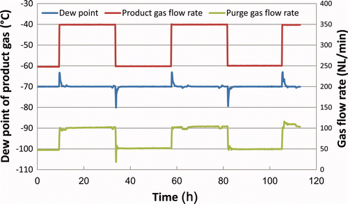
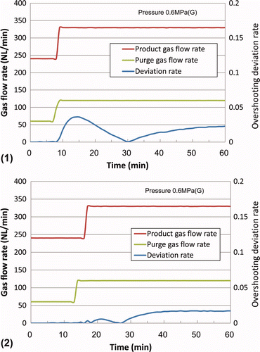
This control method was investigated while changing the product gas (dry air) flow rate in steps, with the results shown in . Overshooting of the exit dew point from the target dew point can be observed for a short time (about 1 h) after an increase in the product gas flow rate. On the other hand, undershooting is observed after a decrease in the product gas flow rate.
Since overshooting of the dew point leads to a decline in the tritium recovery rate, it is undesirable in terms of tritium removal. In actual PID operation, this overshooting should be considered when setting the target dew point to ensure the required tritium recovery performance is met.
2.3.2. Fixed purge ratio operation
In order to limit overshooting, fixed purge ratio operation was carried out, in which the purge gas flow rate is set at a constant value derived from the fixed purge ratio and the target product gas flow rate. Here, the purge ratio is defined as the ratio between the purge gas flow rate to the residual gas (sum of the product gas and the purge gas) flow rate. The results are shown in (1) and 3(2) for pressures of 0.6 and 0.8 MPa(G), respectively.
Figure 3. Transitional change of the dew point under fixed purge ratio operation at (1) 0.6 MPa(G) and (2) 0.8 MPa(G).
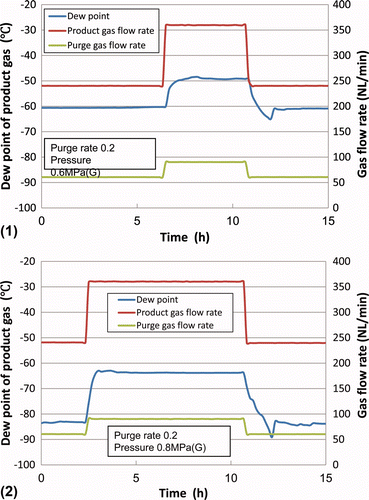
The results in show that overshooting of the dew point after the increase in product gas flow rate could be reduced.
However, the actual dew point changes depending on the product gas flow rate as shown in .
2.3.3. Improvement of fixed purge ratio operation
If the optimal purge ratio for achieving the target dew point can be determined beforehand for each processing gas flow rate, this purge ratio could be applied in operation.
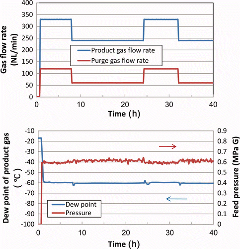
In this experiment, the target dew point is set to −60°C. Steady-state purge ratios for achieving the dew point of −60°C were obtained using PID control for all target feed gas flow rates. These optimum purge ratios were then applied to the optimal fixed purge ratio operation. The results of operation are shown in .
As shown in , optimal fixed purge ratio operation is effective for reducing overshooting and fluctuation of the actual dew point upon changes in the product gas flow rate. also shows that the target dew point of −60°C is achieved within about 1 h of system startup.
Steady-state purge ratios for achieving the target dew point under the target feed gas flow rate could also be estimated analytically as shown in the next section.
In order to more completely suppress overshooting of the dew point, tuning of the timing between the change in purge gas flow rate and the change in product gas flow rate was investigated.
For this evaluation, the transitional deviation rate (R dev) is defined as follows:
shows that the overshooting deviation rate could be suppressed from 0.04 to less than 0.01 by increasing the purge gas flow rate 2–3 min before the increase in product gas flow rate.
Figure 5. Detailed transitional change of the dew point upon an increase in purge gas flow rate (1) with overshooting and (2) without overshooting.
Similarly, shows that the undershooting deviation rate could also be suppressed from 0.05 to less than 0.01 by decreasing the purge gas flow rate 2–3 min before the decrease in product gas flow rate.
Figure 6. Detailed transitional change of the dew point upon an increase in purge gas flow rate (1) with undershooting and (2) without undershooting.
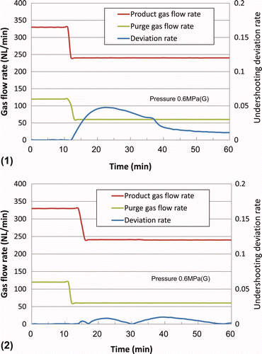
This effect is considered to result from changes in the moisture concentration distribution along the axis of the polymer membrane module upon changes in the processing gas flow rate, as discussed in the following.
3. Analysis
3.1. Analytical model and condition
In order to perform optimal fixed purge ratio operation as described above, it is necessary to first understand the dehumidification characteristics of the polymer membrane module to be used.
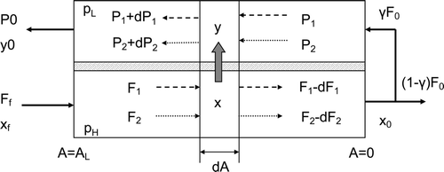
Here, we apply the mass balance analysis model as described previously [Citation11]. A differential model for the present process (countercurrent flow process) is shown in . In the differential model, the flow along the tube and shell sides of the fiber is assumed to follow a plug-flow model, and pressure loss along the flow direction is ignored.
If we consider the change in flow rate of a small part of the module with an area dA, the material balance can be described as follows:
The optimum A L value of the polymer membrane module (UM-C10, Ube Industries) has been previously estimated to be 4 m2 [Citation12]. The dehumidification characteristics of the membrane module (UM-C10) under the operating conditions of the tritium removal system were evaluated by comparison of the analysis with experimental results.
3.2. Analytical results
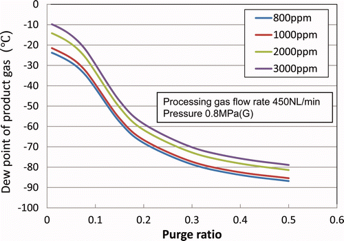
3.2.1. Relationship between the dew point and purge ratio
The relationship between the actual dew point and the purge ratio is shown in for processing gas flow rates (nearly the same as the residual gas flow rate in this system) of 300, 450, and 600 L(NTP)/min under pressure conditions of 0.6, 0.7, and 0.8 MPa(G). In these calculations, the inlet moisture concentration is set at 800 ppm. The experimental results are also plotted for flow rates of 300 and 450 L(NTP)/min.
Figure 8. Relationship between dew point and purge ratio at (1) 0.6 MPa(G), (2) 0.7 MPa(G), and (3) 0.8 MPa(G).
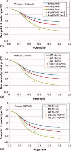
For a flow rate of 450 L(NTP)/min, there is good agreement between the analysis and experimental results at purge ratios above 0.2. For a flow rate of 300 L(NTP)/min, the experimental values are a little higher than the analytical results. This is considered to be a result of disregarding the concentration polarization of the moisture concentration around the surface of the penetration side that results from a decrease in the linear flow velocity of the purge gas under a lower flow rate [Citation11].
Using the results in , it is possible to estimate the optimal fixed purge ratio for maintaining a target dew point under arbitrary processing gas flow rate conditions.
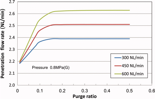
3.2.2. Relationship between penetration flow and purge ratio
The penetration flow rate is defined as the total gas volume (per minute) penetrating from the inner side of the polymer membrane module to the outside. shows the penetration flow rate at different purge ratios. The actual penetration flow rate was evaluated from the difference in purge gas flow rate measured at the membrane module entrance and exit (with an accuracy of ±5 L(NTP)/min).
The calculated value (around 2.5 L(NTP)/min) agreed with the measured value (1–2 L(NTP)/min) within the limits of measurement accuracy.
3.2.3. Relationship between recovery ratio and purge ratio
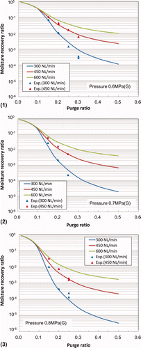
The relationship between the recovery ratio (ratio of exit/entrance moisture concentrations of the membrane module) and the purge ratio is shown in . The experimental results are also plotted for processing gas flow rates of 300 and 450 L(NTP)/min. The analytical results showed good agreement with the experimental results under the operating conditions of the actual tritium recovery system in the LHD.
The dew point at the exit of the membrane module changes depending on the moisture concentration at the entrance under the same operating conditions as shown in as an example. However, the recovery ratio is independent of the feed gas moisture concentration. As such, is a useful guide for design and operation of the tritium recovery system under actual operating conditions.
Figure 10. Relationship between moisture recovery ratio and purge ratio at (1) 0.6 MPa(G), (2) 0.7 MPa(G), and (3) 0.8 MPa(G).
Generally, the tritiated water vapor recovery rate (T recov.) can be defined as follows:
In the present system, the penetrated gas flow rate is less than 1% of the feed gas flow rate, as shown in . In this case, we can make the following approximation to estimate the tritium recovery rate using the recovery ratio in under various operating conditions.
3.2.4. Moisture concentration distribution along axis of membrane module
compares the change in moisture concentration along the axis of the membrane module for processing gas flow rates of 300 and 450 L(NTP)/min under a pressure of 0.8 MPa(G). In , a film area of 0 m2 corresponds to the inlet of the module, while a film area of 4 m2 corresponds to the outlet of the module. In this calculation, the inlet moisture concentration is set at 800 ppm and the outlet concentration is set at 3.4 ppm.
Figure 12. Axial distribution of moisture concentration inside and outside a hollow-fiber membrane module at 0.8 MPa(G).
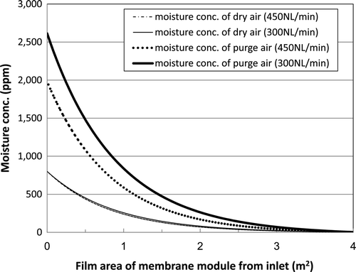
shows that the axial distribution of the moisture concentration of dry air (tube side of the hollow-fiber membrane module) is almost independent of the flow rate. However, the axial distribution of the moisture concentration of the purge gas (shell side of the hollow-fiber membrane module) depends on the flow rate.
If we consider that penetration of water vapor into this polyimide membrane occurs by dissolution and diffusion of water, then the amount of water dissolution outside the hollow-fiber polyimide membrane should change in correspondence with the change in axial vapor concentration as shown in .
Differences in the amount of water dissolution outside the surface of the membrane module will cause a transitional change in the dew point upon the step change in processing gas flow rate.
As shown in (2) and 6(2), shifting the timing of the change in purge gas flow rate relative to the step change in processing gas flow rate could limit any variation in the axial moisture concentration distribution outside the surface of the membrane module.
4. Discussion
4.1. Evaluating application to actual tritium recovery system
shows that a recovery ratio of tritiated water vapor exceeding 95% (decontamination factor: 20) can be expected by setting the purge ratio to 0.15 under an operating pressure of 0.7 MPa(G). If the purge ratio is increased to 0.3, a recovery ratio of 99.9% is expected using the polymer membrane module.
For tritium removal from the gaseous phase, systems combining a catalytic oxidation column and a dehumidification column filled with MS adsorption materials are widely used conventionally. However, a polymer membrane dehumidifier offers the potential for miniaturization of equipment and a reduction in the radioactive waste generated in comparison to a MS adsorption column. In the following, we compare the two methods.
4.2. Configuration and flow of actual removal system with membrane module
In the LHD, two types of tritium recovery systems are planned for installation. One system will recover tritium generated during the plasma experiments (Vacuum Pumping-Gas Treatment System) and the other will enable inspection and maintenance of the LHD vacuum vessel (Vacuum-Vessel Purge-Gas Treatment System) [Citation9].
For the Vacuum-Vessel Purge-Gas Treatment System, we are planning to apply a membrane dehumidifier having a maximum treatment capacity of 300 m3(NTP)/h [Citation13]. The applied configuration and process flow are shown in while summarizes the design conditions. Twelve polymer membrane modules (equivalent to UM-C10 model) are planned for installation in parallel. The disadvantage of a polymer membrane dehumidification system is the time taken to reach the target dew point after starting operation. This delay time is estimated to be less than about 1 h under the present experimental conditions as demonstrated in . As shown in , a small MS adsorption tower is planned for installation in order to accept the processing gas within this delay time and as a temporary backup during shutdown operation if equipment were to break or the performance of the membrane module deteriorate.
Table 2. Design conditions.
This is the Vacuum-Vessel Purge-Gas Treatment System considered for comparison.
4.3. Comparison of equipment specifications
As shown in , operation of the removal system with a membrane module requires an air compressor in addition to the membrane module. On the other hand, operation of the removal system using MS adsorption columns must have a system in place for heating regeneration of the adsorption column using spare adsorption columns.
4.4. Comparison of size of dehumidifier system
An example of typical design specifications for the removal system with the membrane module is shown in . To secure a processing gas flow rate maximum of 300 m3(NTP)/h, 12 of the polymer membrane modules are assumed to be installed in parallel.
Table 3. Design specifications for the system with the membrane module.
As shown in evaluation of the MS adsorption column was carried out assuming a column 1.6 mΦ in inside diameter and 2.8 m in height, which corresponds to the height restriction for installation in the LHD building. In this evaluation, the column is filled with adsorbent to a height of 1 m (filled volume: 1300 kg). If the moisture adsorption capacity of the MS adsorption material is assumed to be 10 wt%, then it is possible to dehumidify moisture in the air up to a volume of 300 m3 (about 2.4 kg of water for a moisture concentration of 1%) over 54 h.
If heating regeneration of the adsorption column is assumed to occur on a 7 day cycle (natural cooling after heating desorption over 12 h), four columns would be required for continuous operation. The required installation area of the air compression machine and the polymer membrane module is estimated to be one-half the installation area of the four adsorption columns, allowing miniaturization of the removal system.
If we assume that the membrane module and adsorption material have equivalent durabilities, the amount of radioactive waste at the time of abandonment will be reduced to about one-quarter for the membrane module design, based on the volume ratio of the membrane module and the adsorption material.
5. Conclusions
To confirm the design specifications of the tritium removal system for the LHD with a commercially available polymer membrane module, we examined the dehumidification characteristics and optimal operation control method under system operating conditions. The following conclusions were obtained:
| 1. | By making the dew point at the module exit a control index, and carrying out PID control of the purge gas flow rate, the target dew point can be made constant under the condition of a constant product gas (dry air) flow rate. However, in the case where the product gas flow rate changes sharply, overshooting of the dew point cannot be ignored. | ||||
| 2. | If the purge ratio for attaining the target dew point is known in advance for each product gas flow rate, overshooting of the dew point upon changes in the product gas flow rate can be suppressed with fixed purge ratio operation instead of PID control. In this operation, it is also possible to largely cancel the overshooting by tuning the timing between the change in the purge gas flow rate and the change in the product gas flow rate. | ||||
| 3. | The dehumidification characteristics necessary for application of the polymer membrane module to the actual removal system were clarified under the system operating conditions. A recovery ratio of tritiated water vapor exceeding 95% (a decontamination factor of 20) can be expected by setting the purge ratio to 0.15 under an operating pressure of 0.7 MPa(G). If the purge ratio is increased to 0.3, a recovery ratio of 99.9% is expected using the polymer membrane module. | ||||
| 4. | The potential miniaturization of the removal system and consequent reduction in radioactive waste generation were estimated for application of a polymer membrane module instead of a MS adsorption column at a treatment flow rate of 300 m3(NTP)/h. Using the membrane module design, the installation area of the system could be reduced to one-half that using MS adsorption columns, and the volume of radioactive waste generated could be reduced to one-quarter. | ||||
Table 4. Design specifications for the system with the MS adsorption column.
Nomenclature
| F f: | = |
total feed gas flow rate (mol/h) |
| F 0: | = |
residual gas flow rate (mol/h) |
| Q 1: | = |
permeation coefficient of water vapor (mol m/m2 s Pa) |
| F 1: | = |
water vapor flow rate at feed side (mol/h) |
| F 2: | = |
airflow rate at feed side (mol/h) |
| Q 2: | = |
permeation coefficient of air (mol m/m2 s Pa) |
| P 1: | = |
water vapor flow rate at permeate side (mol/h) |
| P 2: | = |
airflow rate at permeate side (mol/h) |
| δ: | = |
film thickness (m) |
| x: | = |
water vapor concentration at feed side (molar fraction) |
| y: | = |
water vapor concentration at permeate side (molar fraction) |
| A: | = |
film area (m2) |
| p L: | = |
pressure at permeate side (Pa) |
| p H: | = |
pressure at feed side (Pa) |
| γ: | = |
residual gas purge ratio defined as the ratio of the purge gas flow rate to the residual gas flow rate |
References
- Hayashi , T. , Yamada , M. , Suzuki , T. , Matsuda , Y. and Okuno , K. 1995 . Gas separation performance of a hollow-filament type polyimide membrane module for a compact tritium removal system . Fusion Technol , 28 : 1503
- Hirata , S. , Kakuta , T. , Ito , H. and Suzuki , T. 1995 . Experimental and analytical study on membrane detritiation process . Fusion Technol , 28 : 1521
- Ito , H. , Suzuki , T. , Takanaga , T. , Matsuda , Y. , Konishi , S. and Naruse , Y. 1992 . Separation of tritium using polyimide membrane . Fusion Technol , 21 : 988
- Fukada , S. and Nishikawa , M. 1997 . Analysis of multicomponent permeation through a gas separation membrane and its applications to atmospheric detritiation systems . Fusion Technol , 32 : 220
- Hayashi , T. , Okuno , K. , Ishida , T. , Yamada , M. and Suzuki , T. 1998 . Effective tritium processing using polyimide films . Fusion Eng. Des , 39–40 : 901
- Iwai , Y. , Yamanishi , T. and Nishi , M. 1999 . Steady-state simulation model of gas separation system by hollow-filament type membrane module . J. Nucl. Sci. Technol , 36 : 95
- Ishida , T. , Hayashi , T. , Mori , S. , Suzuki , T. and Nishi , M. 2000 . Design of a membrane atmosphere detritiation system using super high permeation module . Fusion Eng. Des , 49–50 : 839
- Digabel , M.L.E. , Truan , P.A. , Ducrect , D. , Laquerbe , C. , Perriat , P. , Niepce , J.C. and Pelletier , T. 2003 . Glovebox atmosphere detritiation process using gas separation membranes . Fusion Eng. Des , 69 : 61
- Asakura , Y. , Sugiyama , T. , Kawano , T. , Uda , T. , Tanaka , M. , Tsuji , N. , Katahira , K. and Iwahara , H. 2004 . Application of proton-conducting ceramics and polymer permeable membranes for gaseous tritium recovery . J. Nucl. Sci. Technol , 41 : 863
- Asakura , Y. , Sugiyama , T. , Kawano , T. , Uda , T. , Tanaka , M. , Tsuji , N. , Katahira , K. and Iwahara , H. 2005 . Application of new technologies for gaseous tritium recovery and monitoring . Fusion Sci. Technol , 48 : 401
- Asakura , Y. , Tanaka , M. , Uda , T. , Ogawa , H. , Takami , S. , Oya , Y. , Okuno , K. and Fukada , S. 2009 . Design of gaseous tritium recovery system applying commercially available membrane-type dehumidifier . J. Nucl. Sci. Technol , 46 : 641
- Asakura , Y. , Tanaka , M. , Ogawa , H. and Takami , S. 2011 . Application of membrane dehumidifier for gaseous tritium recovery in the LHD . Fusion Sci. Technol , 60 : 1363
- Asakura , Y. and Suzuki , N. 2012 . Planned operation of tritium recovery system based on investigation of LHD exhaust system . Plasma Fusion Res , 7 : 2405009
