Abstract
An efficient dissolution process was established for future reprocessing in which mixed-oxide (MOX) fuels with high plutonium contents and dissolver solution with high heavy-metal (HM) concentrations (more than 500 g dm−3) will be treated. This dissolution process involves short stroke shearing of fuels (∼10 mm in length). The dissolution kinetics of irradiated MOX fuels and the effects of the Pu content, HM concentration, and fuel form on the dissolution rate were investigated. Irradiated fuel was found to dissolve as 102–103 times fast as non-irradiated fuel, but the rate decreased with increasing Pu content. Kinetic analysis based on the fragmentation model, which considers the penetration and diffusion of nitric acid through fuel matrices prior to chemical reaction, indicated that the dissolution rate of irradiated fuel was affected not only by the volume ratio of liquid to solid (L/S ratio) but also by the exposed surface area per unit mole of nitric acid (A/m ratio). The penetration rate of nitric acid is expected to be decreased at high HM concentrations by a reduction in the L/S ratio, but enhanced by shearing the fuel pieces with short strokes and thus enlarging the A/m ratio.
1. Introduction
In the conventional head-end process of a light water reactor (LWR) reprocessing plant, spent fuels are sheared to 20–50 mm in length and dissolved in nitric acid solution in which the heavy-metal (HM, U + Pu) concentration ranges from 100 to 300 g dm−3. Future reprocessing plants will treat spent mixed-oxide (MOX) fuels with high Pu content (mass ratio of Pu to heavy metal in fuel), as a larger amount of MOX fuel will be used in the LWR than at present and research on the fast reactor (FR) fuel cycle will progress. The dissolution rate of MOX fuel is depressed upon increasing the Pu content [Citation1]. On the other hand, a modified PUREX process has been suggested for FR fuel reprocessing, which includes a crystallization process for rough uranium recovery prior to the simplified extraction process [Citation2]. For the required uranium recovery to be achieved in the crystallization process, the dissolver solution has to be prepared with a high HM concentration of more than 500 g dm−3 [Citation2]. Under such conditions, fuel dissolution will be substantially slower because the highly concentrated condition requires a larger amount of fuel to be treated and a smaller volume of nitric acid. The most effective countermeasure against this problem is the pulverization of fuel pellets to enhance the effective surface area of the fuel in contact with the nitric acid [Citation3]. Such mechanical pretreatment of fuels, however, requires additional equipment in the reprocessing plant, such as a grinder mill. An alternative to pulverization for enhancing the effective surface area of the fuel pieces is to vary the form of the sheared fuel pieces, i.e., to obtain fuel pieces sheared with short strokes. In a previous study on shearing system design for FR reprocessing, it had been confirmed that highly pulverized fuel could be achieved easily by shearing the simulated fuel pins with a length of 10 mm [Citation4]. However, the impacts of the Pu content and concentration on the dissolution rate of irradiated MOX fuel have not yet been clarified quantitatively.
The objective of this study is to show the applicability of fuel pieces sheared with short strokes to the dissolution process under highly concentrated conditions. Because the dissolution kinetics of irradiated MOX fuels is very complicated, there is still a lack of knowledge of the reaction mechanism and the rate-determining factors and their formulation. We especially focus on rate-determining factors such as the Pu contents, HM concentration, and fuel form, from the point of view of their effects on the chemical reaction or mass transfer. Hence, at the beginning of this paper, we will summarize the current knowledge on the dissolution kinetics models developed for irradiated MOX fuel. The results of dissolution tests using irradiated MOX fuels under highly concentrated conditions are presented, and the kinetics of U, Pu, and fission-product (FP) nuclides are discussed. Second, the effect of the Pu content on the dissolution rate is investigated, because the proportion of refractory PuO2 is expected to have a huge impact. Then, the dominant factors considered to affect the dissolution rate under highly concentrated conditions are discussed, taking into account the penetration of nitric acid through the fuel matrices and the chemical reaction at the fuel surface.
2. Two different dissolution models
The dissolution reaction of MOX fuel in nitric acid is expected to consist of a chemical reaction between UO2 or PuO2 and nitric acid on the solid surface, and the mass transport phenomena of reactants such as nitric acid or products such as UO2 2+ and Pu4+. The dissolution kinetics have been developed using two different approaches. Each model has a particular interpretation of the access path of nitric acid to the fuel and of the reacting zone in the fuel matrix. The first model considers the homogeneous chemical reaction only on the solid surface (so-called “surface-area model”), and the other considers the penetration and diffusion of nitric acid to the fuel surface and through the fuel matrices (so-called “fragmentation model”). In this section, we summarize these two different models, but it should be noted that we never compare their technical superiorities. These models should be applied in accordance with the evaluations of the effects of rate-affecting factors. For example, since the Pu content in MOX fuel is expected to affect only the chemical reaction on the solid surface, we can use the surface-area model. When the effects of HM concentration and fuel form are discussed, we can simply evaluate these factors by using the fragmentation model, as described later.
2.1. Surface-area model
If we assume that the chemical reaction occurs homogeneously on the surface of the sheared fuel pieces, the dissolved amount at time t can be described by:
2.2. Fragmentation model
Hodgson [Citation6] proposed the fuel dissolution model via the fragmentation of solid material by the penetration and diffusion of nitric acid through fuel matrices. In this model, the dissolution process follows the exposure of unexposed fuel surfaces by nitric acid and the dissolution of the exposed part of the fuel. The dissolution rate of the fuel is assumed to be proportional to the mass of fuel exposed to nitric acid.
3. Experimental
3.1. Materials
The MOX fuels used in this study had been irradiated in the Mk-I, Mk-II, and Mk-III cores of the experimental fast reactor “JOYO” of the Japan Atomic Energy Agency. In this study, in order to prepare the surface geometry of the sheared pieces as uniform as possible, a single fuel pin was sheared using a shear blade. The cross section of fuel was observed to have a smooth surface, being kept roughly circular in shape. The ratio of powdered fuel after the shearing were estimated to be less than 10 wt%, and only sheared pieces of fuel were used for the dissolution tests. It should be noted that, in commercial reprocessing plants, fuel assemblies are sheared, and their surface of cross sections are expected to be coarser than that obtained in this study. Furthermore, the powdered ratio would be higher than that from single-pin shearing. In such conditions, the dissolution rate would be larger in commercial plants than those obtained in this study.
Fuel pins from the Mk-II and Mk-III cores were sheared with 10-mm length. The Pu content after irradiation, assembly average burn-up, and cooling time of these fuels are 27.4%, 54,700 MWD/t, and 8000 days, respectively, for the Mk-II fuel, and 22.4%, 53,300 MWD/t, and 1000 days, respectively, for the Mk-III fuel. A fuel pin from the Mk-I core was sheared with 20-mm length and used for the dissolution test, which aimed at obtaining the data on dissolution rate of fuel pieces with intermediate length between 10 mm and 30 mm. The Pu content after irradiation, assembly average burn-up, and cooling time of the Mk-I fuel are 15.8%, 40,100 MWD/t, and 8400 days, respectively.
3.2. Dissolution test
Dissolution tests were conducted to clarify the impacts of the Pu content in fuel, the HM concentration in the product solution (described as “[HM]p”, 260–510 g dm−3), and the fuel form (length of fuel) on the dissolution rate. The experimental conditions in this study are detailed in . In the scheme of tests A–D, the effect of air bubbling on the dissolution rate was also investigated, but no clear tendency was observed.
Table 1. Experimental conditions in this study.
Table 2. Experimental data on the composition of sample and product dissolver solutions.
Table 3. The composition of insoluble residues.
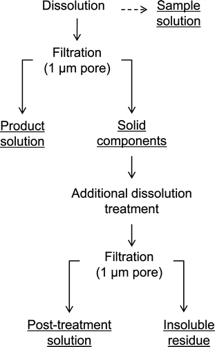
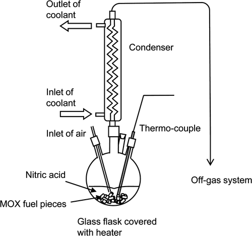
shows the procedure of sample separations conducted in dissolution tests. A 1-dm3 glass flask covered with heater was used in this study, as shown in . A specified amount of fuel (sheared with a length of 10 mm) and nitric acid were poured into the flask at room temperature (25–30°C), and the mixture was heated up to and maintained at 95 ± 5°C. While the dissolution proceeded, samples of the dissolver solution in the flask were removed periodically in the tests A, C, and E, and the concentrations of U, Pu, and FP nuclides in the solution were measured using absorption spectroscopy for U and Pu and gamma spectrometry for FP nuclides. Meanwhile, the reaction progression was also monitored by counting the 85Kr released from the fuel matrices using a NaI scintillator placed on the off-gas system of the test apparatus. We assumed the reaction had finished when the count number of released 85Kr dropped to and stayed at the level of the background count. In each test, the dissolution reaction finished within 3 h.
3.3. Measurement of composition of the dissolver solutions and the insoluble residues
After the test had finished and the dissolver solution had been cooled to room temperature, and solid components dispersed in the dissolver solution, such as hulls, non-dissolved fuels, and other components consisting of FPs, were collected by suction filtration on a glass-fiber filter with 1-μm pore diameter. Concentrations of U, Pu, and FPs in the product solution were measured using same method as the sample measurement for U, Pu, and FP nuclides, and using Inductively Coupled Plasma-Atomic Emission Spectroscopy (ICP-AES) for FP elements. The collected solid components were immersed in 0.25 dm3 of 3 M nitric acid at 95°C for up to 2 h to recover the non-dissolved fuels. After this additional dissolution treatment, the treated solution was clarified by using the same procedure as described above. Concentrations of U, Pu, and FPs in the post-treatment solution and those in the insoluble residue were measured using same method as the product solution measurement for U and FPs, and alpha spectrometry for Pu. Prior to the measurement, the insoluble residue was treated by melting at 750°C with sodium peroxide and sodium carbonate, and the mixture was dissolved into 3 M nitric acid solution.
4. Results and discussion
4.1. Comparison among dissolution behaviors of U, Pu, and FP nuclides
and list the elemental compositions of dissolver solutions (samples and product solutions) and insoluble residue through dissolution tests A–F. According to the measured concentrations in post-treatment solutions, up to 1% of initial mass of heavy metal and negligibly small amount of FPs were estimated to be dissolved by the additional dissolution treatment. The dissolution ratios of each nuclide were calculated from the measured concentration by using the following formula:
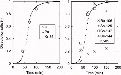
The fission products showed specific behavior as shown in . The release of the noble gas 85Kr was similar to the behavior found for the dissolution of U or Pu, indicating that 85Kr was distributed homogeneously in the fuel matrices [Citation7]. Past research showed that the ratio of released 85Kr can adequately represent the dissolution ratio calculated from the dissolved mass of fuel [Citation5]. Thus, the dissolution ratio can be described as the ratio of released 85Kr. The dissolution of lanthanide FP nuclides, represented as 144Ce in , also showed similar behavior to that of U and Pu. 137Cs showed a relatively high dissolution ratio in the early phase of dissolution, which meant that dissolution was suppressed in the late phase. The reason for this depression of Cs is still unclear, but it could be explained by the precipitation of dicesium tetravalent plutonium hexanitrate, PuCs2(NO3)6, in the sample solution upon cooling for measurement [Citation8]. However, since the molecular ratio of Cs to Pu in the fuel is estimated to be less than 4% from the calculation with ORIGEN, the impact of the precipitate on the dissolution rate of fuel is expected to be negligibly small. The dissolution ratio of 125Sb was 85% at the end of the reaction, while 15% was detected from the insoluble residue. The dissolution ratio of 106Ru was extremely low compared to those of the other nuclides. Most Ru is expected to be transferred to the insoluble residue, forming metallic alloys with other noble metals such as Mo, Tc, Pd, and Rh [Citation7,Citation9].
Therefore, the FP nuclides noted here are expected to have little impact on the dissolution of U and Pu because these fuel components seem to behave independently. Hence, we describe only the dissolution of U and Pu [10] or 85Kr, which describe the dissolution of fuel matrices well. The impacts of the Pu content, HM concentration, and fuel form on the dissolution rate are discussed in the following sections.
4.2. Impact of Pu content on dissolution rate of irradiated MOX fuels
4.2.1. Pu content effect in surface-area model
It has been reported that the Pu content has an enormous impact on the fuel dissolution rate. Uriate et al. [Citation1] noted that non-irradiated MOX pellets become more refractory as their Pu content increases. This relationship is expressed by the following equation:
Table 4. Experimental conditions in previous studies with sheared pieces (30-mm in length).
If the Pu content changes, each value of k, y and E mentioned in Equation (2) may be different. Because there are not sufficient data enough to determine those parameters systematically, we solely introduced an adjustment parameter, c, which can be affected by Pu content, on Equation (2).
Figure 4. Comparison of dissolution ratios calculated by surface-area model with the experimental values (released ratios of 85Kr).
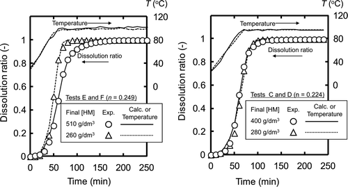
Table 5. Calculated instantaneous dissolution rates with different Pu contents by surface-area model.
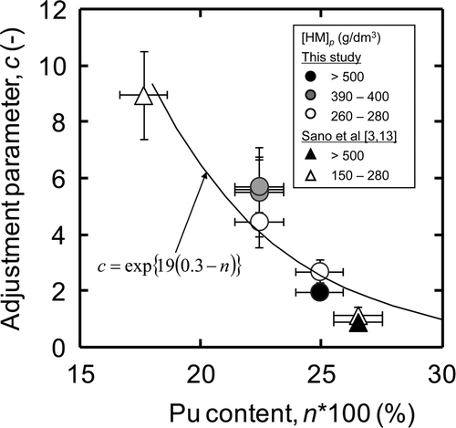
In this section, we directly compared the c values obtained from the dissolution tests with the different HM concentrations and the different fuel forms. This evaluation procedure is thought to be reasonable due to following two reasons. First, though a minor depression of the c value was observed at the HM concentration of higher than 500 g dm−3, e.g., comparison between test E (c = 2.0 ± 0.2) and test F (c = 2.7 ± 0.4), this difference is expected to be much trivial than the effect of Pu content. Second, the length of fuel is expected to have little impact on the dissolution rate described with surface-area model because we assumed the homogeneous surface reaction being based on the observation of the aspect of cross section (see section 3.1.). Therefore, we evaluated the effect of Pu content on the c values, neglecting the effects of the HM concentration and the fuel form.
As shown in , the c values tend to decrease with increasing Pu content at the range from 0.18 to 0.30. The “a” in Equation (11) was determined to be approximately 19 by minimizing the squared difference between the c values listed in and the values calculated from Equation (11). The calculated values were described as a solid line in . The instantaneous dissolution rate at unit surface area is expressed as follows:
4.2.2. Promotion effect by irradiation
For comparison with non-irradiated fuels from previous studies, the dissolution rates under standard dissolution conditions, i.e., initial HNO3 concentration of 8 M and temperature of 95°C, with different Pu contents were estimated. As for the irradiated MOX fuel, the instantaneous dissolution rate (mol cm−2 min−1) under standard dissolution conditions was calculated for each Pu content by applying Equation (10) with the c values listed in , [H+] = 8 M, and T = 368.15 K. Meanwhile, the dissolution rate of non-irradiated fuel had been reported by many workers under several temperature conditions [Citation1,Citation14–Citation16]. For calculation of the rate at 95°C, the activation energy that had been reported for UO2 dissolution and estimated to be approximately 60 kJ/mol [Citation14] was used accordingly. The instantaneous dissolution rates calculated for the irradiated fuels are shown in compared with those for the non-irradiated fuels. The dissolution rate equation for the non-irradiated fuels was also calculated using Equation (9) and shown in . It is clear that the irradiated MOX fuels dissolved 102–103 times faster than the non-irradiated ones with the same Pu content. The possible reasons for the enhanced dissolution of irradiated fuels are expected to be, for example, the catalytic effect of noble metal fission products such as Pd on the oxidizing dissolution of UO2, the evolution of the effective surface area of the fuels by irradiation, or a decrease in the solid density of the fuels upon irradiation. As for the catalytic effect of noble metals, Trummer et al. [Citation17] reported that UO2 powders containing 3 wt% of Pd dissolved five to six times faster than non-Pd powders in H2O2 + HCO3 solution. The same effect of noble metals was also reported by Ikeda et al. [Citation18]. However, from the reports in the previous papers mentioned above, the effects of noble metals seem to be too weak to explain the 102–103 order of enhancement obtained in this study. The effect of density deterioration is also expected to be small. Therefore, the most probable explanation is the evolution of the surface geometry upon irradiation. Nevertheless, it was clarified that an increased Pu content decreases the dissolution rate of irradiated MOX fuels, as reported in previous studies using non-irradiated fuels.
4.3. Impact of heavy metal concentration in product solution
4.3.1. Dissolution rate at high HM concentration
It is generally said that the amount of solute in a dissolver solution has two opposing impacts on the dissolution rate. The promoting effect appears when a solute species, particularly UO2 2 +, shows catalytic behavior toward its dissolution reaction. The catalytic interaction of the UO2 2+ ion was indicated in some previous works [Citation1,Citation14], but the reaction mechanism is not clear. Ikeda et al. [Citation15] claimed that the uranyl ion itself does not have a catalytic effect, but that the nitric acid ion accompanied by a uranyl ion acts as a reactant in the dissolution reaction. On the contrary, the inhibiting effect appears when the amount of solute in the dissolver solution approaches the solubility of these species and the chemical reaction is suppressed. By comparing the results of tests A–D, in which the HM concentration varied from 260 to 400 g dm−3, the dissolution rates were comparable to one another within a range from 1.7 ± 0.4 to 2.1 ± 0.6 mmol cm−2 min−1 (see ), and no significant effect of HM concentration was observed. On the other hand, on comparing tests E and F, the instantaneous dissolution rate obtained at 510 g dm−3 (0.74 ± 0.08 mmol cm−2 min−1) was found to be slightly lower than that at 260 g dm−3 (1.0 ± 0.2 mmol cm−2 min−1). This result seems to show that the inhibiting effect is stronger than the promoting effect. The uranium concentration of the dissolver solution tested in this study, however, is up to 510 g dm−3, which is far less than the solubility of uranyl nitrate in nitric acid [Citation19]. Under such conditions, the inhibiting effect on the chemical reaction is evaluated to be negligibly small. Therefore, we should take physical transport processes such as the diffusion and penetration of nitric acid into the fuel matrices into account. These transport processes are macroscopic, not microscopic ones such as the transport through the diffusion layer near the surface. Another kinetic approach for the dissolution behavior of irradiated MOX fuels is needed for the application of these macroscopic transport processes such as the diffusion and penetration of nitric acid.
4.3.2. Evaluation by fragmentation model
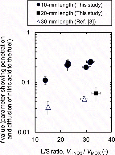
In this study, the appropriate f values in the fragmentation model were determined by using the minimized squared difference between the dissolution ratios calculated using Equations (4)–(6) and experimental ones for each of the test condition. Typical examples of calculation results are shown in , and the appropriate f values calculated in tests A–F (10-mm length) are shown in . The volume ratios of nitric acid () to the MOX fuel (V
MOX) are also listed as “L/S ratio” in . The values of
are referred from the initial volume of nitric acid (dm3) listed in . The values of V
MOX are calculated dividing the mass of MOX fuel (g) in by the solid density of MOX fuel, which is assumed as approximately 104 g dm−3 [Citation1]. By comparing the results of tests A–D, no significant change of the f value was observed, even though the L/S ratio was decreased from 31.7 to 22.6 as the HM concentration in the product solution increased from 260 to 400 g dm−3. By comparing the results of tests E and F, we see that the f value decreased significantly from 0.20 to 0.11 as the HM concentration in the product solution increased from 260 to 510 g dm−3, where the L/S ratio was decreased from 30.0 to 13.9. The relationship between calculated f value and the L/S ratio with tests A–F (10-mm length) is summarized in . The L/S ratio seems to have negligibly small impact on the f value with the HM concentrations less than 400 g dm−3, where the L/S ratio is larger than ∼20. However, at the highly concentrated condition, where the HM concentration is more than 500 g dm−3, the decrease of L/S ratio is expected to have a great impact on the dissolution rate of the irradiated MOX fuel, making the penetration and diffusion of nitric acid into the fuel matrices less efficient significantly.
Figure 7. Comparison of dissolution ratios calculated by the fragmentation model with the experimental values (released ratios of 85Kr).
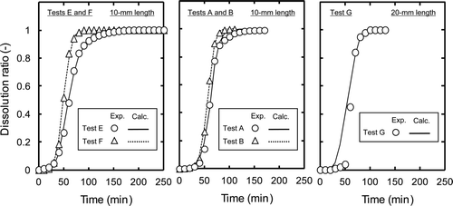
Table 6. Calculated f values for different fuel forms and heavy-metal concentrations by fragmentation model.
4.4. Effect of short stroke shearing on dissolution performance
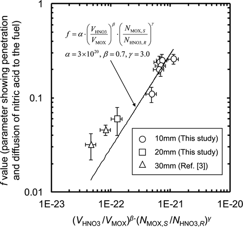
The form of the fuel pieces can affect the penetration and diffusion of nitric acid into the fuel rather more than the chemical reaction via the surface of the sheared fuel. Since the f value is also expected to be affected by the physical configurations of the dissolution test apparatus such as the shape of the dissolver cell and the agitation conditions, we used only data obtained with similar experimental apparatus to that used in this work, i.e., small-scale apparatus and agitation by air bubbling. The f values obtained for the dissolution tests using sheared pieces of 20-mm length (test G) and pieces of 30-mm length (Prev-1, and Prev-2) are shown in and , being compared with those of 10-mm length. It is noted that the f values of 10-mm length are larger by 3–5 times than those of 20-mm length and 30-mm length with similar L/S ratio. Even at the HM concentration higher than 500 g dm−3 where the L/S ratio are 14–15, the f value of 10-mm length, 0.11 ± 0.02, is larger than that of 30-mm length, 0.032 ± 0.010. This improvement in f value is expected to be due to the enlargement of the effective surface area exposed to solution by short stroke shearing. Since the penetration and diffusion of nitric acid are initiated with the path through the external surface of the sheared pieces exposed to the solution, the f value can be affected not only by the L/S ratio but also by the ratio of the number of moles of (U, Pu)O2 on the effective surface area of the sheared pieces exposed to the solution (N MOX, S ) to the number of moles of nitric acid which have reacted with MOX fuel (N HNO3, R ). The value of N MOX, S was calculated from following equation:
where d MOX, M W, and L are the density (∼10 g cm−3), molecular weight (∼270 g mol−1), and lattice constant of (U, Pu)O2 (cm), respectively. In this study, the value of L was assumed to be approximately 5.5 × 10⁻⁸ cm as reported by Sari et al. [Citation20]. The value of N HNO3, R was estimated from the number of moles of U and Pu dissolved, assuming following chemical reaction:
The relationship among the f value, the L/S ratio, and the A/m ratio can be expressed by the following formula:
As a consequence, under highly concentrated conditions where the HM concentration reaches more than 500 g dm−3, as the L/S ratio decreases, the penetration and diffusion of nitric acid through fuel matrices are depressed significantly. However, by shearing the fuel pins with short strokes, i.e., 10-mm length, dissolution can be enhanced through the enlargement of the effective surface areas of the fuels. The relationship between the penetration and diffusion rates of nitric acid, the L/S ratio, and the effective surface area is expressed by Equation (14), in which the empirical numbers are determined for the test apparatus configuration.
5. Conclusion
The dissolution kinetics of spent MOX fuels were investigated through dissolution tests using fuel pieces irradiated in the “JOYO” fast reactor. The effects of the Pu content, HM concentration, and fuel form on the dissolution rate were discussed. The dissolution rate of irradiated fuel was shown to be 102–103 times higher than that of non-irradiated fuel, but the rate decreased with Pu content, as expected from the results of previous reports using non-irradiated pellets or powders. Kinetic analysis by the fragmentation model, which considers the processes of the penetration and diffusion of nitric acid through the fuel matrices, indicated that the dissolution rate of irradiated fuel is affected not only by the volume ratio of liquid to solid (L/S ratio), which decreases the penetration rate of nitric acid, but also by the exposed surface area per unit mole of nitric acid (A/m ratio). The penetration rate of nitric acid, which controls the dissolution rate of the fuel, was expected to be depressed at high HM concentrations, but enhanced for fuel pieces sheared with short strokes (i.e., with an enlarged specific surface area of fuel). Then, the dissolution process with short stroke shearing can be applied to maintain the dissolution efficiency of MOX fuels with high Pu contents of up to 30% at high concentrations of up to 500 g dm−3.
Acknowledgements
In this study, all of the dissolution tests using irradiated mixed-oxide fuels were conducted in the Chemical Processing Facility (CPF) of Japan Atomic Energy Agency.
References
- Uriate , AL and Rainey , RH . 1965 . Dissolution of High-density UO2, PuO2, and UO2-PuO2 pellets in inorganic acids , USA : Oak Ridge National Laboratory (ORNL) . (ORNL–3695)
- Takata , T , Koma , Y , Sato , K , Kamiya , M , Shibata , A , Nomura , K , Ogino , H , Koyama , T and Aose , S . 2004 . Conceptual design study on advanced aqueous reprocessing system for fast reactor fuel cycle . J. Nucl. Sci. Technol , 41 : 307 – 314 .
- Sano , Y , Miyachi , S , Koizumi , T and Koyama , T . 2005; 2005 . Dissolution of irradiated MOX fuel for highly concentrated solution (paper no. 259) . Paper presented at: Proceedings of GLOBAL . October 9–13 2005; 2005 . [CD-ROM]
- Higuchi , H , Koizumi , K , Hirano , H , Tasaka , M , Washiya , T and Kobayashi , T . 2010 . Development of short stroke shearing technology for FBR fuel pin . J. Power Ener. Syst , 4 ( 1 ) : 244 – 251 .
- Nemoto , S , Shibata , A , Shioura , T and Tanaka , Y . 1995 . Studies on the dissolution of mixed oxide spent fuel from FBR , Japan : Power Reactor and Nuclear Fuel Development Corporation . (Dounen-giho 95–43) [in Japanese]
- Hodgson , TD . 1987 . A model for fuel dissolution via fragmentation . Paper presented at: Proceedings of International Conference on Nuclear Fuel Reprocessing and Waste Management RECOD 87 . Aug 23–27 1987 .
- Kleykamp , H . 1985 . The chemical state of the fission products in oxide fuels . J. Nucl. Mater , 131 : 221 – 246 .
- Nakahara , M , Koizumi , T and Nomura , K . 2011 . Precipitation behavior of dicesium tetravalent plutonium hexanitrate in cooling crystrallization of uranyl nitrate hexahydrate . Nucl. Technol , 173 : 183 – 190 .
- Lausch , J , Berg , R , Koch , L , Coquerelle , M , Glatz , JP , Walker , CT and Mayer , K . 1994 . Dissolution residues of highly burnt nuclear fuels . J. Nucl. Mater , 208 : 73 – 80 .
- Oudinet , G , Munoz-Viallard , I , Aufore , L , Gotta , MJ , Becker , JM , Chiarelli , G and Castelli , R . 2008 . Characterization of plutonium distribution in MIMAS MOX by image analysis . J. Nucl. Mater , 375 : 86 – 94 .
- Ikeda , Y , Yasuike , Y , Nishimura , K , Hasegawa , S , Mason , C , Bush , R and Takashima , Y . 1999 . Dissolution behavior of pulverized irradiated fuels in nitric acid solutions . J. Nucl. Sci. Technol , 36 ( 4 ) : 358 – 363 .
- Schiefelbein , GF and Lerch , RE . 1971 . Dissolution property of UO2-PuO2 thermal reactor , USA : Battelle Pacific Northwest Laboratory . (BNWL–1581)
- Sano , Y , Koyama , T and Funasaka , H . 2000 . Summary of the dissolution experiments of the irradiated fast reactor fuels in CPF , Japan : Japan Nuclear Cycle Development Institute . (JNC TN8400 2000-016) [in Japanese]
- Taylor , RF , Sharratt , EW , de Chazal , LEM and Logsdail , DH . 1963 . Dissolution rates of uranium dioxide sintered pellets in nitric acid systems . J. Appl. Chem , 13 : 32 – 40 .
- Ikeda , Y , Yasuike , Y , Nishimura , K , Hasegawa , S and Takashima , Y . 1995 . Kinetic study on dissolution of UO2 powders in nitric acid . J. Nucl. Mater , 224 : 266 – 272 .
- Fukasawa , T , Ozawa , Y and Kawamura , F . 1991 . Generation and decomposition behavior of nitrous acid during dissolution of UO2 pellets by nitric acid . Nucl. Technol , 94 : 108 – 113 .
- Trummer , M , Nilsson , S and Jonsson , M . 2008 . On the effects of fission product noble metal inclusions on the kinetics of irradiation induced dissolution of spent nuclear fuel . J. Nucl. Mater , 378 : 55 – 59 .
- Ikeda , Y , Yasuike , Y and Takashima , Y . 1993 . Acceleration effect of noble metals on dissolution rate of UO2 powders in nitric acid . J. Nucl. Sci. Technol , 30 ( 5 ) : 485 – 487 .
- Research Group for Aqueous Separation Process Chemistry . 2008 . Handbook on process and chemistry of nuclear fuel reprocessing , Japan : Japan Atomic Energy Agency . (JAEA-Review 2008-037) [in Japanese]
- Sari , C , Benedict , U and Blank , H . 1970 . A study of the ternary system UO2-PuO2-Pu2O3 . J. Nucl. Mater , 35 : 267 – 277 .
![Figure 6. Comparison of instantaneous dissolution rate calculated at [H+] = 8 mol dm−3 and T = 95°C between non-irradiated and irradiated MOX fuel.](/cms/asset/b8c9e493-dabc-4714-b1c5-2ffee6a3eaeb/tnst_a_757466_o_f0006g.gif)
