Abstract
In the design of MW-class spallation target system, using mercury to produce practical neutron applications, keeping the highest level of safety is vitally important. To establish the safety of spallation target system, it is essential to understand the thermal hydraulic properties of mercury. Through thermal hydraulic experiments using a mercury experimental loop, which flows at the rate of 1.2 m3/hr maximum, the following facts were experimentally confirmed. The wall friction factor was relatively larger than the Blasius correlation due to the effects of wall roughness. The heat transfer coefficients agreed well with the Subbotin correlation. Furthermore, for validation of the design analysis code, thermal hydraulic analyses were conducted by using the STAR-CD code under the same conditions as the experiments. Analytical results showed good agreement with the experimental results, using optimized turbulent Prandtl number and mesh size.
1. Introduction
The Japan Proton Accelerator Research Complex (J-PARC) Project was started by Japan Atomic Energy Agency (JAEA) and the High-Energy Accelerator Research Organization (KEK). [Citation1] In the project, a next generation spallation neutron source coupled with a MW-class proton beam has been developed to produce high-intensity neutrons for fundamental sciences and nuclear engineering fields. Mercury is to be used as the target material. While high-intensity neutrons are produced by the spallation reaction between mercury and protons, high-density heat is also generated in the mercury. Heated area on the target vessel is about 280 mm in width and 80 mm in height. Maximum heat flux against the mercury is about 10 kW/cm2. In simple calculation, it is estimated that more than 1.0 m/s in the mercury velocity is necessary to remove the heat load in the mercury target. The cooling ability in the mercury target is therefore one of the design issues that must be addressed to maintain structural integrity. To design the mercury target, the authors planned to use a commercial analysis code as the STAR-CD code. However, commercial codes are not optimized to use with liquid metal. It was therefore thought that the analytical code would have to be varied for use in mercury target design.
The heat transfer coefficients of liquid metal, including mercury under flow conditions, are expressed using the Peclet number (Pe) which is a multiple of the Reynolds number (Re) and the Prandtl number (Pr), and several experimental correlations have been proposed in the past studies. But the experimental apparatus dimensions and conditions for obtaining experimental data, to propose the correlations as Subbotin or Martinelli–Lyon formulae, were not sufficiently clear to use for analysis and validation of the analytical code. Therefore, the authors carried out heat transfer and flow experiments to clarify the validity and predictability of existing experimental correlations.
This paper presents the results of experiments on heat transfer coefficients and pressure drop characteristics obtained by using a mercury experimental loop with the maximum flow rate of 1.2 m3/hr, as well as analytical results obtained using the k—ɛ turbulent model with STAR-CD code.
2. Heat transfer experiments with mercury
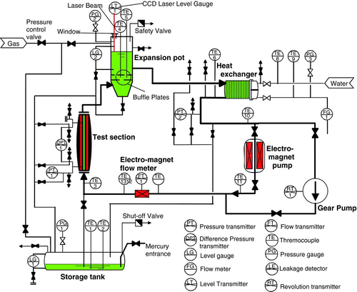
2.1. Schematics of mercury experimental loop
shows a schematic diagram of the loop. The loop consists of a heated test section, an expansion pot, an electromagnetic pump, a gear pump, an electromagnetic flow meter and a heat exchanger. Two types of pumps are installed in parallel to be used independently. The piping was 25A-Sch80, with an internal diameter of 25 mm and a thickness of 4.5 mm. The expansion pot was pressurized by argon gas to maintain constant pressure in the loop. The maximum elevation differential of the pipelines was about 1.5 m and total piping length was about 11 m. The maximum inventory of mercury was about 30 liters. All components were made of type 316 stainless steel. The loop was covered with a steel tray and acryl plates to prevent the leakage of mercury and its vapor, and the air in the loop enclosure was exhausted continuously through a charcoal filter working as a mercury vapor trap.
Figure 1 Schematic diagram of the mercury experimental loop
The specifications of the mercury experimental loop were as follows:
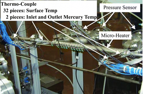
and show schematic drawings of the heated test section and an external view, respectively. The heated test section was a circular tube of 15A-Sch80, made of type 316 stainless steel, with internal diameter of 14.3 mm, thickness of 3.7 mm and 1000 mm in length (effective heated length 600 mm). The test section was the stainless steel tube covered with heater block of 4.5 kW. Three grooves were cut spirally on the copper block surface in which three heaters were installed in parallel over the whole length of the heater block. Also, 32 thermocouples were installed on the surface of the stainless steel tube. The thermocouples for tube surface temperature measurement were set into grooves along the axial direction, at 20 mm intervals. Two thermocouples were inserted into the tube to measure the inlet and outlet mercury temperature. The inlet and outlet straight section was 140 mm, which was about 10 times of the tube inner diameter. Pressure loss was measured over a distance of 640 mm including the heated region.
Figure 2 Schematic drawing of the test section
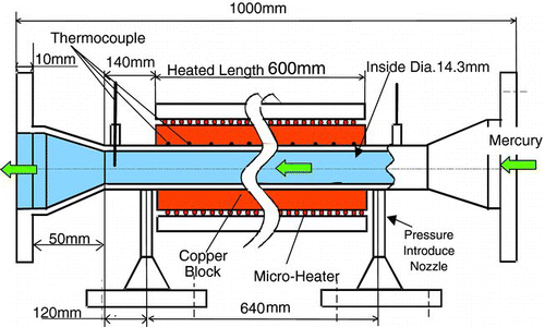
Figure 3 External view of the test section
The measurement precision was as follows (precision is expressed by the relative difference from measurement value):
2.2. Experimental conditions
The experimental conditions are as follows:
The surface temperature inside the stainless steel tube is calculated by using 1-D heat conduction equation under the steady-state condition.
The new piping surface was covered with oxidized layer. The slipping (not sufficiently wet) was occurred between the fluid (liquid metal) and the piping surface, because the surface tension and other factor were influenced by the oxidized layer. To obtain heat transfer and pressure drop in mercury target, a sufficiently wet condition (no slip) has to be achieved. A pre-operation was conducted to obtain the wet condition. For about 8 hours, pressure drop was still unsteady and increased with operating time. Thereafter, the pressure drop became constant with time. A pre-operation was conducted more than 12 hours, and the wet condition was considered sufficient to conduct the heat transfer experiments.
2.3. Experimental results
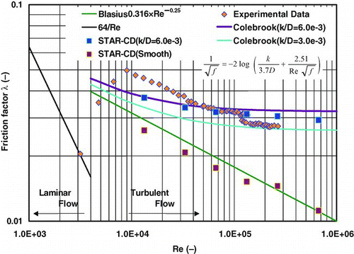
shows the relationship between the pressure drop and the mercury velocity in a tube of 0.64 m in length. In this figure, the correlations by Blasius and Colebrook are shown for comparison with the experimental data. The Blasius correlation is a general correlation for smooth condition. The Colebrook correlation is well known to express the effect of the wall roughness, [Citation2] and is expressed as follows:
Figure 4 Relationship between pressure drop and mercury velocity
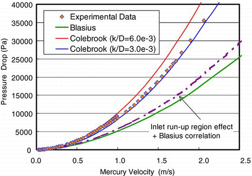
For Colebrook correlations, two conditions of k/D = 6.0 × 10⁻³ and 3.0 × 10⁻³ are shown in this figure, where D is the inside diameter of the test section. The test section inlet region was about 140 mm, representing about 10 × D, but the boundary layer run-up region was about 20–30 times longer than the tube diameter. Thus, the experimental data has a capacity to include the effects of run-up region pressure drop. Therefore, the Blasius correlation with run-up region effects is shown by the dotted line in Figure . At 1.0 m/s of mercury velocity, the experimental data of pressure drop reaches about 9000 Pa, which is about two times as the Blasius correlation, and is between the two roughness cases of Colebrook correlation. For the 2.0 m/s case, the experimental data of pressure drop reaches about 35,000 Pa, which is about two times as the Blasius correlation and almost same as the roughness case, k/D = 3.0 × 10⁻³ of the Colebrook correlation. Except for very low velocity condition, most data are higher than those estimated with the Blasius correlation. Moreover, the experimental data are higher than the Blasius correlation with effects of the run-up region.
Thus, it is thought that the experimental pressure drop is affected by the wall roughness. The experimental data lie between two lines, suggesting that the wall roughness (k/D) of this tube is estimated between 6.0 × 10⁻³ and 3.0 × 10⁻³. In these experiments, the test section inside diameter D was 14.3 mm, and the roughness k was calculated as 85 and 35 μm. This estimation is suitable for the test section piping material. The test section piping was made of solid-drawn steel, as the surface roughness of solid-drawn steel is about 50 μm. [Citation2]
shows the relationship between the friction factor and the Re number. The Blasius correlation and the Colebrook correlation are shown as same as for Figure . The inlet effect is also shown in Figure . The experimental data are about 50%–100% higher than the Blasius correlation in the turbulent flow region. Moreover, they are higher than the Colebrook correlation at the transient region between the laminar and the turbulent flow.
Figure 5 Relationship between friction factor and Reynolds number
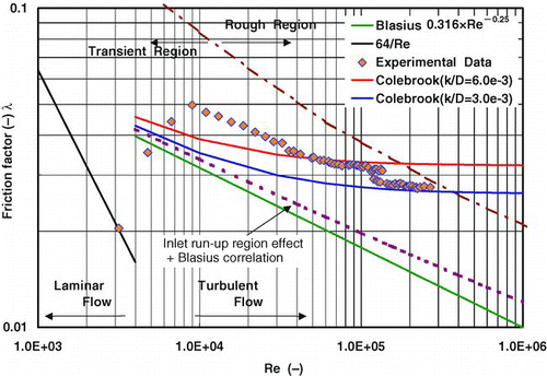
The boundary of wall roughness region is shown in the figure. Most experimental data lie in the transient region of wall roughness effect for the friction factor. They show a tendency to become constant at Re > 200,000 – this tendency being characteristic of the roughened wall friction factor. In the constant region, the experimental data exists between the two cases of the Colebrook correlation. Therefore, it was thought that the present results could have been caused by a relatively large wall roughness. However, friction factors obtained by a machined test section agree well with the Blasius correlation,[Citation3] which was carried out during the commissioning test of the loop.
shows the roughness Reynolds number of mercury. Roughness Reynolds number is expressed as the following equation:
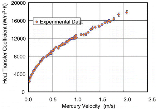
shows the relationship between the heat transfer coefficient and the mercury velocity. The heat transfer coefficient is calculated from the average of some data by the thermocouples around 460 mm from the start of heated region, considering about the heat balance in the test tube. The measurement accuracy, which is distribution of the experimental data selected for the calculation of the heat transfer coefficient, is shown for each data. The measurement accuracy is thought to be satisfactory in this experiment. As shown in this figure, the heat transfer coefficient at the lowest mercury velocity (about 0.05 m/s) was 2500 W/m2·K, that at 1.0 m/s was about 12,000 W/m2·K and at 2.0 m/s was 18,000 W/m2·K. The increasing rate of the heat transfer decreased with increasing the mercury velocity in the velocity range lower than 0.5 m/s. The increasing rate of the heat transfer coefficient became constant for the velocities higher than 0.5 m/s.
Figure 6 Roughness Reynolds number of mercury (roughness k = 35 and 85 μm)
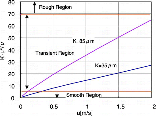
Figure 7 Relationship between heat transfer coefficient and mercury velocity
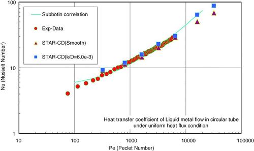
shows the relationship between the Nusselt number (Nu) and the Peclet number (Pe). The Peclet number is expressed by multiple of the Reynolds number and the Prandtl number (Pe = Re × Pr). In this figure, the following correlations [Citation3] are also shown:
Figure 8 Experimental data and correlations expressed as relationship between Nusselt number and Peclet number
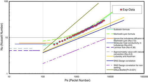
Martinelli–Lyon correlation:
Subbotin correlation:
Lubarsky and Kaufman correlation:
SNS Design correlation by Siman-Tov et al. [Citation4]:
It seems that the experimental results agree with the Subbotin correlation, in which the experimental results are expressed as follows:
As the heat transfer data are not so high as those of other correlations, it is considered that the effect of the wall roughness on the heat transfer coefficient is relatively small compared with that on the pressure drop under the experimental conditions. Since mercury has high heat conductivity and a low Prandtl number, the temperature boundary layer is much larger than the velocity boundary layer. The temperature boundary layer thickness is about 50 times as the velocity boundary layer thickness in the mercury flow. The heat transfer coefficient was about 2500 W/m2·K, obtained under the lowest mercury velocity (about 0.05 m/s). This value is also same with the Dittus–Boelter correlation, which is used for water etc. The rate of increase for the Dittus–Boelter correlation, which is applicable in the region of Prandtl number 1–100, is very high compared with the experimental data or other correlation, because the Prandtl number of mercury was about 0.02 under present experimental condition. This result was caused by the difference of the Prandtl number between the liquid metal as mercury, and other liquid as water. It is thought that this difference has to be taken into account in the analysis of mercury flow and heat transfer.
3. Three-dimensional thermal hydraulic analysis of mercury flow
3.1. Analytical model and conditions
Thermal hydraulic analysis was conducted using STAR-CD, which was a commercial calculation code and planned to be adopted in the design calculation of the mercury target vessel.
shows the analytical model and mesh. The analytical model has the same dimension as the experimental test section. The internal diameter was 14.3 mm and the heated length was 600 mm. The length of the inlet run-up region was 400 mm. The maximum number of meshes was limited to 750,000 in total due to computer capacity. The axial mesh size was 2 mm. It was decided to keep the radial mesh size smaller than the boundary layer thickness. The radial direction dimensionless distance, which is expressed as y+, is determined as follows:
Figure 9 Analytical model for heat transfer analysis
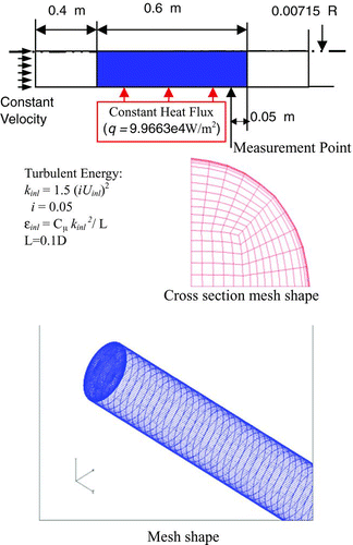
The y+ calculated from mesh size nearest to the wall in this calculation was adjusted to less than 30 under several velocity conditions as shown in . Therefore, the mesh size became smaller as the mercury velocity increased.
Table 1 y+ value for Reynolds number
The analytical conditions were as follows:
The turbulent Prandtl number was estimated by the following equation proposed by Myong and Kasagi [Citation6]:
The properties of mercury, when it was at a temperature of 30°C, are as follows:
In the analysis, two cases were considered: (1) a smooth inner surface was assumed and (2) a roughened inner surface was assumed. STAR-CD has a function for calculating cases of the roughened wall surfaces, in which k/D was used as a parameter for the wall roughness. In this analysis, the k/D value was selected as 6.0 × 10⁻³ (k = 85 μm), based upon the experimental results.
3.2. Analytical results
shows the friction factor in the circular tube. In this figure, the experimental data, the Colebrook correlation and the Blasius correlation are shown for comparison with the analytical results. The Colebrook correlation as in Equation (1) was used to calculate the roughened surface friction factor.
Figure 10 Comparison with experimental and analytical results of friction factor
The analytical results in the roughened case agree with both the experimental data and the Colebrook–White correlation. Strictly speaking, the analytical results are a little lower than the Colebrook–White correlation in higher Reynolds number region of Re > 200,000. It is thought that the mesh size nearest to the wall in that region is large for calculating the friction factor, because y+ in high-velocity regions, as calculated from the mesh size, are slightly higher than 30, as shown in Table . It can be concluded that the STAR-CD code is applicable to calculate the friction factor of mercury flow under real conditions by using the wall roughness as a parameter. To obtain the accurate result, the mesh size must be adjusted to make it smaller than the boundary layer.
shows the heat transfer coefficient in a circular tube, calculated by STAR-CD for two cases of wall roughness, as same as the calculation for friction factors, expressed as the relationship between the Peclet number and the Nusselt number. In this figure, the experimental data and the Subbotin correlation are shown for comparison with the analytical results. The difference between the two analytical cases was not so large, but the case of roughened surface was slightly higher than the case of smooth surface. The analytical results agree with the experimental data and the Subbotin correlation, in the range of Pe = 500 to 10,000, which includes the operating condition of the mercury target system (Pe = 6000–8000). In higher Peclet number regions, the roughened case results show better agreement with the Subbotin correlation. Moreover, the increasing rate becomes lower with the Peclet number. The heat transfer coefficient is thought to be affected by the mesh size as in the calculation of the friction factor. Since the mesh size was not fine enough for higher velocity regions, it is considered that the roughness effect became higher with increasing velocity in this analytical model.
Figure 11 Comparison with experimental data, analytical results and correlations expressed as relationship between Nusselt number and Peclet number
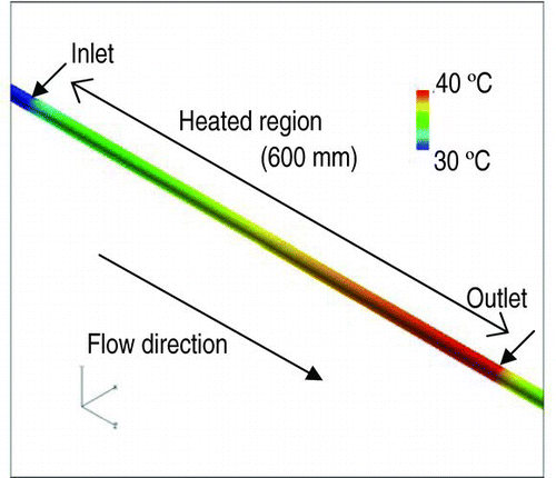
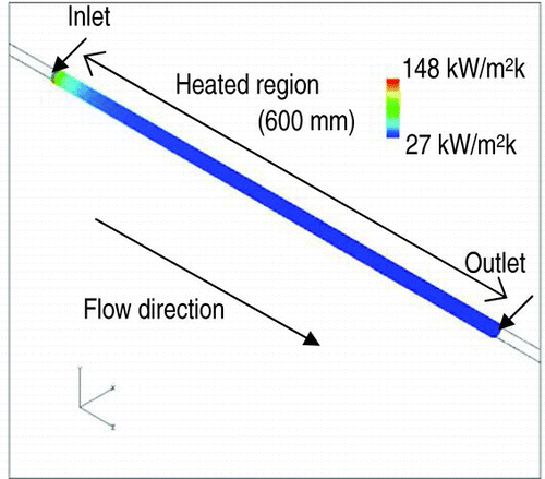
shows wall temperature distribution of 3-D analytical results for the case of mercury velocity at 2.07 m/s. The maximum temperature of the mercury in the heating region was about 40.4°C and the temperature difference between the inlet and the outlet was about 10.4°C. It is a reasonable result and almost same as the experimental result.
Figure 12 Temperature distribution of the 3-D analysis
shows the heat transfer coefficient distribution of 3-D analytical results in the case of mercury velocity at 2.07 m/s. The maximum value appears nearest to the heating region inlet and becomes lower with increasing distance from the inlet. Moreover, the heat transfer coefficient becomes constant near the outlet of the heating region.
Figure 13 Heat transfer coefficient distribution of the 3-D analysis
shows the heat transfer coefficient in relation to the flow direction. Additionally, the Gnielinski correlation [Citation7] is shown in this figure, which is expressed as follows:
Figure 14 Heat transfer coefficient along with flow direction
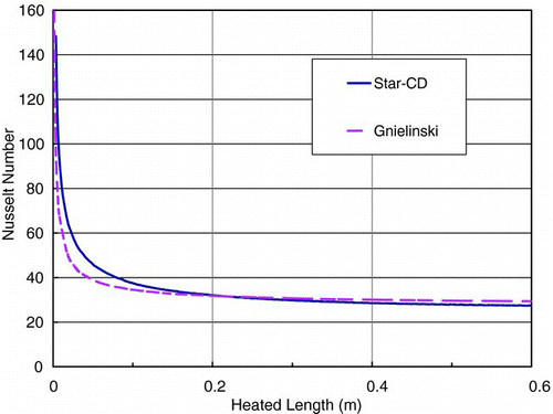
As shown in this figure, the Nusselt number is relatively high near the inlet region, but it becomes stable downstream after 0.2 m. Most of the analytical results show good agreement with the Gnielinski correlation. This result concludes that the analysis with STAR-CD can express the run-up region heat transfer coefficient.
Based on these results, analytical parameters for a mercury target system can be decided, and it is concluded that STAR-CD can predict mercury heat transfer coefficient well by using an appropriate analytical parameter with a standard k—ɛ model, a turbulent Prandtl number of 1.5 and a mesh size for a y+ of 30. It is therefore judged that STAR-CD could be applied for the thermal hydraulic analysis of mercury target vessels.
4. Concluding remarks
Thermal hydraulic experiments with the mercury experimental loop and analytical studies for mercury were conducted. The following conclusions were obtained:
| 1. | The pressure drop is much larger than the Blasius correlation, because the wall roughness of the test section piping was relatively large under the tested conditions. | ||||
| 2. | The heat transfer coefficients agreed well with the Subbotin correlation, and the data are expressed as follows: | ||||
| 3. | The heat transfer coefficients, obtained by the thermal hydraulic analysis with the STAR-CD code, agreed with the experimental results by using that the turbulent Prandtl number is 1.5 and radial mesh size is optimized to be y+ = 30 in the analysis. | ||||
It is considered from these conclusions that the analytical results by the STAR-CD are in good agreement with the experimental results under the actual conditions for the spallation neutron target, as the mercury velocity is around 1.0 m/s. Therefore, it is verified that the STAR-CD code is applicable for the design analysis of the mercury target vessel and other mercury systems.
References
- 1999 . The joint project for high-intensity proton accelerators , Tokyo : JAERI . JAERI-Tech 99-056
- Kaminaga , M , Terada , A , Ishikura , S , Teshigawara , M , Sudo , T and Hino , R . 1999 . “ Mercury target development for JAERI spallation neutron source ” . In Proceeding of 7th International Conference on Nuclear Engineering (ICONE-7) Tokyo , , Japan 1999 Apr 19-23; ICONE-7123
- JSME . 1979 . JSME data book: hydraulic losses in pipes and ducts] Tokoyo Japan Society of Mechanical Engineering; Japanese
- Siman-Tov , M , Wendel , M , Haines , J and Rogers , M . 1997 . “ Thermal-hydraulic analysis of the liquid mercury target for the national spallation neutron source ” . In Proceeding of the Second Advanced Reactor Safety Conference (ARS’97) Orlando , Florida (ARS'97) June 1-4; (USA)1997
- JSME . 1997 . “ JSME data book: heat transfer] ” . In Japan Society of Mechanical Engineering , 4th ed 107 Tokyo Japanese
- Myong , H K , Kasagi , N and Hirata , M . 1989 . Numerical prediction of turbulent pipe flow heat transfer for various Prandtl number fluids with the improved k–ɛ turbulent model . JSME Int J. , 32 ( 4 ) : 613 – 622 .
- Gnielinski , V . 1976 . New equations for heat and mass transfer in turbulent pipe and channel flow . Int J Chem. Eng. , 16 ( 2 ) : 359