Abstract
In order to confirm the irradiation behavior of ODS steels and thus judge their applicability to fuel claddings, fuel pin irradiation tests using 9Cr and 12Cr-ODS claddings developed by JAEA were conducted to burn-up of 11.9 at% and neutron dose of 51 dpa in the BOR-60. Superior properties of the ODS claddings concerning FCCI, dimensional stability under irradiation and so on were confirmed and indicated good application prospects for high burn-up fuel. On the other hand, anomalous irradiation behaviors, fuel pin failure and the microstructure change containing coarse and irregular precipitates, occurred in a part of the fuel pin with 9Cr-ODS cladding. This paper describes evaluation of the obtained irradiation data and the investigation results into the cause of the anomalous irradiation behaviors.
1. Introduction
In a commercialized fast breeder reactor (FBR) cycle system, there are two important technological tasks to improve the economical performance: the development of high burn-up fuel to attain the average burn-up of 150 GWd/t and the development of a high temperature plant system to attain the coolant outlet temperature of 550 °C [Citation1]. This average burn-up is equivalent to 250 dpa with the maximum neutron dose, and the cladding temperature reaches approximately 700 °C. Japan Atomic Energy Agency (JAEA) has developed oxide dispersion strengthened (ODS) ferritic steels as the most promising cladding material to be used in such a severe environment [Citation2–Citation6].
It is important to confirm the irradiation behaviors for fuel pins to judge the applicability of ODS claddings. In material irradiation tests carried out in Joyo to the neutron dose of 33 dpa at irradiation temperatures between 420 and 835 °C, superior mechanical properties of ODS claddings were obtained [Citation7–Citation10]. In addition, ODS cladding fuel pin irradiation tests using BOR-60 have been conducted under the framework of JAEA-Research Institute of Atomic Reactors (RIAR) collaborative work [Citation11]. The integrity of the ODS cladding fuel pins and superior fuel compatibility of ODS claddings to burn-up of 5.1 at% and neutron dose of 21 dpa were confirmed in these irradiation tests [Citation12]. In this paper, the irradiation test results of ODS cladding fuel pins irradiated at high burn-up in the BOR-60 reactor are presented.
2. Irradiation tests
The main objectives of the irradiation tests using the BOR-60 for the ODS cladding fuel pins were to demonstrate the integrity of ODS claddings to high burn-up and to obtain irradiation data, e.g., fuel and cladding chemical interaction (FCCI). Therefore, two experimental fuel assemblies (EFAs), VS423E and VS424E, were prepared. The target burn-ups were set to 10 at% and 15at % for VS423E and VS424E, respectively, which exceed the burn-up of the first irradiation test in BOR-60 [Citation11, Citation12]. The neutron doses equivalent to these burn-ups were 50 dpa and 75 dpa, respectively. The target cladding mid-wall temperature of each EFA was set between 650 and 700 °C during the entire irradiation period. These target irradiation conditions are summarized in .
Table 1 Irradiation condition of ODS cladding fuel pins in BOR-60 irradiation tests
2.1. Fuel pin design and fabrication
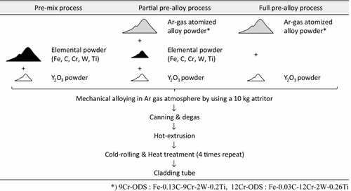
9Cr-ODS martensitic steel and 12Cr-ODS ferritic steel were provided as the fuel claddings in common with the first irradiation test [Citation11, Citation12]. Chemical compositions of these ODS claddings are shown in . These ODS claddings differed in not only the Cr content but also the manufacturing process. shows the manufacturing process of ODS claddings used for BOR-60 irradiation tests. 9Cr-ODS claddings were manufactured by the pre-mix process and 12Cr-ODS claddings were manufactured by the partial pre-alloy process. The pre-mix process refers to the fabrication process using the elemental powder (Fe, Cr, C, W, Ti) and Y2O3 powder as raw material powders, and the partial pre-alloy process refers to the fabrication with the Ar-gas atomized alloy powder and Y2O3 powder with a small amount of elemental powder for minor control of chemical composition. In addition, the manufacturing process using the Ar-gas atomized alloy powder and Y2O3 powder without the elementary powder is designated as the full pre-alloy process.
Table 2 Chemical compositions of ODS claddings used for BOR-60 irradiation tests. (wt%)
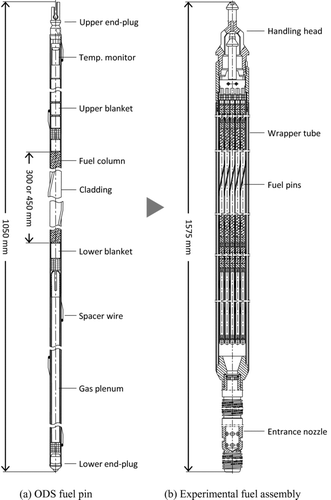
The claddings were used on the fuel pins, in combination with vibro-packed MOX fuels. The main technical characteristics and schematic drawings of the ODS cladding fuel pins are shown in and (a). The fuel pins were the wrapping wire type and each pin had a length, outer diameter and cladding wall thickness of 1050 mm, 6.9 mm and 0.4 mm, respectively. The fuel column lengths differed for the 9Cr-ODS and 12Cr-ODS cladding fuel pins, and were 300 mm and 450 mm, respectively. Besides, the 9Cr-ODS cladding fuel pins were given an enlarged gas plenum by removing the lower blanket pellets. These modifications were conducted to maintain the integrity of the 9Cr-ODS cladding fuel pins; the cumulative damage fraction (CDF) was controlled smaller than 0.3, when the burn-up of 15 at% was attained. These fuel pins were sealed by pressurized resistance welding (PRW) method with an upper-end plug by JAEA [Citation13]. The welding conditions were as follows: 16 ms for welding period, 16 kA for current and 7 kN for contact force [Citation11,Citation13]. The lower end-plug was welded by the tungsten inert gas (TIG) end-face fusion method by RIAR [Citation11]. Vibro-packed MOX fuels with added 5–7 wt% U metal getter particles were used, and Pu content was set to 15 wt%. In addition, a modified 316 stainless steel tube was inserted with the ODS cladding fuel pins as a temperature monitor to verify the irradiation temperature from microstructural observation and hardness measurement in post-irradiation examination (PIE). Details of the design, fabrication and inspection of ODS cladding fuel pins have been reported elsewhere [Citation11].
Table 3 Main technical characteristics of ODS cladding fuel pins in BOR-60 irradiation tests
2.2. Assembling of EFAs
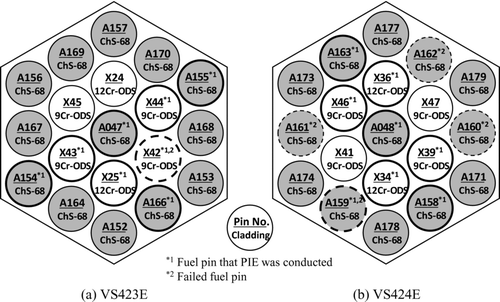
A schematic drawing of an EFA is shown in Figure , and the fuel pin configurations in each EFA are shown in Figure . Each EFA had a bundle of 19 fuel pins which included four fuel pins with 9Cr-ODS cladding, two fuel pins with 12Cr-ODS cladding, and 13 fuel pins with Russian austenitic stainless steel ChS-68 (0.06C-16Cr-15Ni-2Mo-2Mn-Ti-V-B) cladding [Citation14]. ChS-68 cladding, which has many actual use results for the driver fuel pins of BOR-60 and BN-600, was used as a reference for comparative evaluation of FCCI behavior.
2.3. Irradiation test results
The actual irradiation conditions and the irradiation histories of each EFA are shown in and . The VS423E was loaded in the fifth row of the BOR-60 reactor core, and that was irradiated from the 81A-th campaign that started in August 2005. However, irradiation of VS423E was interrupted after the end of that campaign because fuel pin failure was detected by the in-pile leak test. The VS423E was unloaded from the core and non-destructive examination (NDE) was conducted to identify the failed fuel pin. As a result, it was confirmed that one of the ChS-68 cladding fuel pins had failed. Therefore, the irradiation test of ODS cladding fuel pins was continued from the 83-rd campaign that started in April 2006, after exchanging all ChS-68 cladding fuel pins for new ones and reassembling the EFA. The VS423E was irradiated until the 86A-th campaign that finished in March 2008 and attained the targeted burn-up of 10.5 at% and neutron dose of 45 dpa. No fuel pin failure was detected in VS423E by the in-pile leak test conducted after completion of the 86A-th campaign. On the other hand, VS424E was irradiated from the 83-rd campaign to the 87B-th campaign that finished in October 2008, and attained burn-up of 11.9 at% and neutron dose of 51 dpa. Although it had been planned to irradiate to burn-up of 15 at% and neutron dose of 75 dpa, irradiation of VS424E was stopped at the end of the 87B-th campaign because fuel pin failure was detected by the in-pile leak test. It was confirmed that this failure was ChS-68 cladding fuel pin as discussed in Section 4.1.
Table 4 Irradiation history of experimental fuel assemblies in BOR-60 irradiation tests
The irradiation temperature of the ODS cladding fuel pins calculated by RIAR based on BOR-60 actual operation condition was 700 °C at a maximum and 670 °C on average, and those values had satisfied the target temperature range. However, the actual irradiation temperature, which was evaluated from the results of the microstructure observation and hardness measurements of the modified 316 stainless steel tube temperature monitor inserted with the ODS cladding fuel pins and ChS-68 cladding fuel pins, exceeded the RIAR-calculated value. From these results, the possibility that the irradiation temperature of ODS cladding fuel pins reached around 800 °C was shown. The detailed evaluation concerning the irradiation temperature is taken up in Section 4.1.
3. Post-irradiation examination
In order to remove decay heat, both EFAs were cooled for one month in the reactor core, and 5 to 7 months in an inert gas atmosphere after unloading from the reactor core. EFAs were carried into the hot-cell after removing the residual sodium by using 45%-alcoholic water and flowing water. After dismantling of EFAs, visual inspections of fuel pin bundle and disassembly were performed. Then detailed visual inspections for each ODS cladding fuel pin were conducted. As a result, it was confirmed that the integrity of ODS cladding fuel pins loaded in VS424E was maintained with no failure, no significant deformation, and no corrosion. On the other hand, in VS423E, occurrence of failure of one 9Cr-ODS cladding fuel pin was confirmed. Details of this phenomenon are described in Section 4.2.
The rest of this section describes mainly PIE results on the ODS cladding fuel pins irradiated in VS424E.
3.1. Fuel pin outer diameter measurement
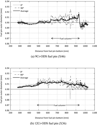
Outer diameter measurements to evaluate the dimensional stability of the ODS cladding fuel pins were performed by using a contact-type profilometer after removing the spacer wire. Representative measurement results of ODS cladding fuel pins irradiated in VS424E are shown in . A slight increase of outer diameter was observed around a fuel column part in both 9Cr-ODS and 12Cr-ODS cladding fuel pins. The strain of outer diameter of all ODS cladding fuel pins was less than 0.5%, and the dimensional stability of the ODS cladding fuel pins was confirmed.
3.2. Microstructure observation
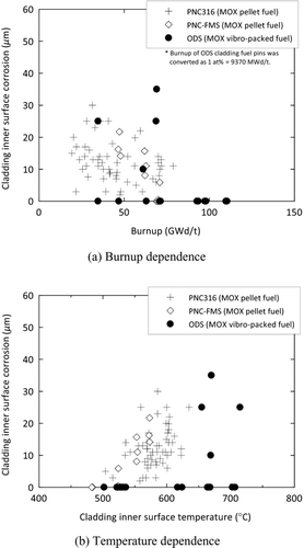
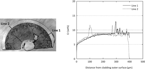
In order to evaluate the FCCI and the outer surface corrosion of ODS claddings, a metallographic observation was carried out, mainly at two places, for each fuel pin at the core center corresponding to the highest burn-up and the upper part of the fuel column corresponding to the highest cladding mid-wall temperature. shows the optical micrographs (cross section) in the upper part of the fuel column of X46 pin irradiated in VS424E as a representative example of the 9Cr-ODS cladding fuel pin. Average cladding mid-wall temperature during an irradiation period, neutron dose and burn-up of this position were approximately 670 °C, 28 dpa and 7.6 at%, respectively. As shown in these photographs, significant FCCI was not observed. On the other hand, a different reaction layer from the matrix in the range of about 60 μm from the cladding outer surface was observed. As a result of conducting a line analysis using an electron probe micro analyzer (EPMA), it was clear that Cr content in the reaction layer decreased to about half that in the matrix as shown in . Such decreasing behavior of Cr content occurred only in the upper part of the fuel column irradiated at high temperature, and did not occur below the core center. As an example of the 12Cr-ODS cladding fuel pin, the optical micrographs (cross section) in the upper part of the fuel column of X36 pin irradiated in VS424E are shown in . The irradiation conditions for the X36 pin were the same as for the X46 pin. FCCI at a depth of about 35 μm was observed clearly in the inner surface of the 12Cr-ODS cladding (Figure (a)). And a different reaction layer like in the 9Cr-ODS cladding was observed about 30 μm from the cladding outer surface. Generally, it is thought that the higher Cr content steel has the superior corrosion resistance. The outer surface corrosion behavior accorded with Cr contents for the two claddings, 9Cr-ODS and 12Cr-ODS. However, as for FCCI behavior, the opposite tendency occurred only in the 12Cr-ODS cladding. Although it can be considered that the inhomogeneous microstructure of 12Cr-ODS cladding was this cause, it requires more detailed evaluation. These results were summarized and compared with the data of modified 316 stainless steel (PNC316) and conventional ferritic steel (PNC-FMS) claddings, which were irradiated with pellet type MOX fuels. (a) and (b) show the burn-up dependence and the temperature dependence of FCCI, respectively. Here, the temperature of the horizontal axis of Figure (b), which was calculated based on BOR-60 actual operation conditions, was considered to be lower than the actual temperature. From these figures, it was obvious that the FCCI of ODS claddings was below or equal compared with that of PNC316 and PNC-FMS claddings. In particular, at the lower temperature below 650 °C in Figure (b), the FCCI of ODS claddings was not observed. Here, it is necessary to note that the oxygen-to-metal (O/M) ratio of ODS cladding fuel pins is low, i.e. about 1.93, as vibro-packed MOX fuels containing U metal getter particles were used whereas the O/M ratios of PNC316 and PNC-FMS cladding fuel pins are 1.95–1.99. The cladding inner surface corrosion is effectively prevented by the lower O/M ratio, because the low oxygen potential restricts the chemical reaction of the cladding material with fission products and fuel. In fact, it was shown that the FCCI is surely restricted by lowering O/M ratio of the fuels from the extensive irradiation tests of PNC316 and ChS-68 fuel pins [Citation15, Citation16]. These results indicated that the inner corrosion of the ODS claddings by FCCI could be controlled by lowering the oxygen potential in the fuel pins using U metal getter, even in low Cr content cladding such as 9Cr-ODS steel.
Figure 5 Optical micrographs of 9Cr-ODS cladding fuel pin (X46) irradiated in VS424E (top of fuel column; distance from core center = 213 mm)
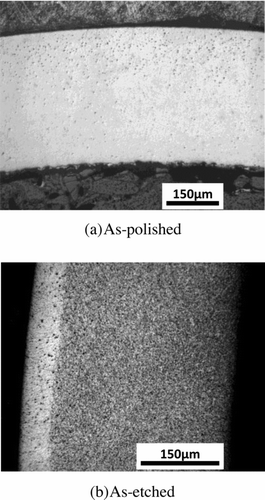
Figure 6 Result of EPMA line analysis of 9Cr-ODS cladding fuel pin (X46) irradiated in VS424E (top of fuel column; distance from core center = 205 mm)
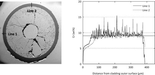
Figure 7 Optical micrographs of 12Cr-ODS cladding fuel pin (X36) irradiated in VS424E (top of fuel column; distance from core center = 215 mm)
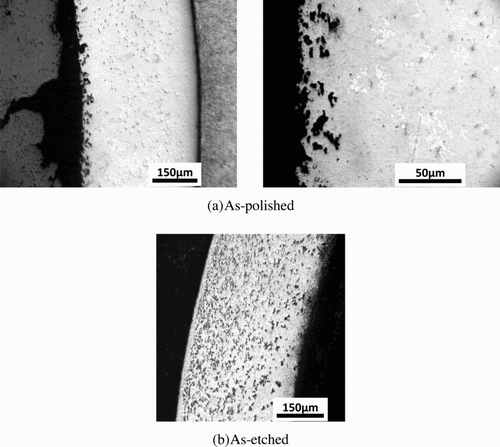
Figure 8 FCCI of the irradiated ODS claddings compared with the FCCI of the modified 316 stainless steel (PNC316) and conventional ferritic steel (PNC-FMS) claddings
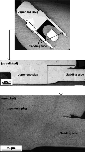
The metallographic observation of the upper-end plug joined by the PRW method was carried out to confirm its integrity. As a representative example, optical micrographs (longitudinal section) of the 9Cr-ODS cladding fuel pin (X46) irradiated in VS424E are shown in . Average temperature during the irradiation period and neutron dose of this position were approximately 670 °C and 1 dpa, respectively. As shown in these photographs, significant microstructure changes, cracking, etc. did not occur in that welded part. The integrity of the welded part was confirmed for other 9Cr-ODS and 12Cr-ODS cladding fuel pins, too. These results showed that the PRW method would be a very promising welding method for ODS claddings.
4. Anomalous irradiation behaviors
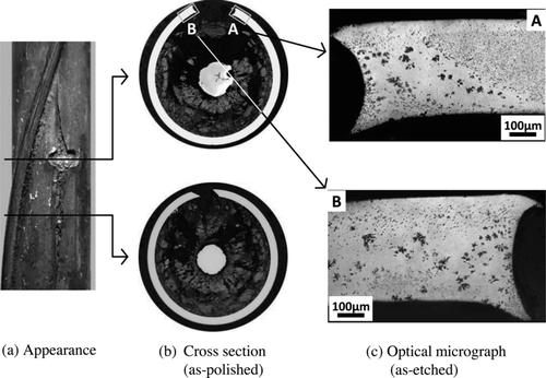
One 9Cr-ODS cladding fuel pin (X42) irradiated in VS423E failed at the position below 20 to 50 mm from the fuel column top. As shown in (a) and (b), there was a round through-hole in the center of the failed position, and a crack spread up and down starting from there. Average cladding mid-wall temperature during an irradiation period, neutron dose and burn-up of this position are approximately 650 °C, 32 dpa and 8.5 at%, respectively. It was thought that the 9Cr-ODS cladding fuel pin would not break under such irradiation conditions based on the results of simple creep damage evaluation of cladding; other effects must have led to the failure. In addition, an anomalous microstructure change containing coarse and irregular precipitates occurred in the vicinity of the failed position as shown in Figure (c). This kind of microstructure change was a very anomalous phenomenon which has not been reported previously in neutron-irradiated ferritic steels, including ODS steels, irradiated in Joyo [Citation10]. From these facts, it was suspected as a cause of anomalous irradiation behaviors that the irradiation temperature was higher than the designed temperature, and 9Cr-ODS claddings provided to this irradiation test had abnormalities such as manufacturing defects.
Figure 10 Photographs of the failure position of 9Cr-ODS cladding fuel pin (X42) irradiated in VS423E (distance from core center = 175–205 mm)
4.1. Evaluation of irradiation temperature
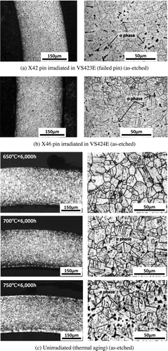
In order to evaluate the temperature of this irradiation test, a metallographic observation of the modified 316 stainless steel tube, which was inserted as a temperature monitor in the upper blanket region of the ODS cladding fuel pin (Figure (a)), was carried out. These results are shown in (a) and (b). The precipitations of the σ phase, which were indicated by the arrows in optical micrographs, were observed in both the modified 316 stainless steel tubes. Figure (c) reproduces optical micrographs of the same materials which were subjected to the thermal aging test at 650, 700 and 750 °C for 6000 hours. From these optical micrographs, it is clear that the σ phases precipitate at around 700 °C and increase with a rise in temperature. And also the microstructures of the modified 316 stainless steel tubes inserted with the X42 and X46 pins are quite similar to the microstructure of the thermal aged materials at 750 °C and 700 °C. Therefore, it was considered that the irradiation temperature of the modified 316 stainless steel tubes inserted with the X42 and X46 pins reached 750 °C and 700 °C, respectively. From the relationship between these results and the insertion position of the modified 316 stainless steel tubes, it was estimated that the maximum irradiation temperature of the ODS claddings reached around 770 °C in VS423E and around 720 °C in VS424E.
In looking at the Cr depletion behavior at the outer surface of the 9Cr-ODS cladding, as shown in , the X43 pin (VS423E) showed depletion at a depth of 100–150 μm, which was approximately twice the depth of the X46 pin (VS424E) shown in Figure . According to the evaluation result of relationship between the temperature and the diffusion length of Cr calculated by using the diffusivity of Cr, the diffusion length of Cr was approximately doubled with a rise in temperature of 50 °C. Here, the diffusivity of Cr was calculated by the Arrhenius equation which applied 1.21 × 10⁻⁴ m2/s and 2.37 × 10⁵ J/mol for a frequency energy and an activation energy, respectively [Citation17]. As a result, it was estimated that the irradiation temperature of VS423E would be roughly 50 °C higher than that of VS424E, and this supported the result mentioned above.
Figure 12 Result of EPMA line analysis of 9Cr-ODS cladding fuel pin (X43) irradiated in VS423E (top of fuel column; distance from core center = 211 mm)
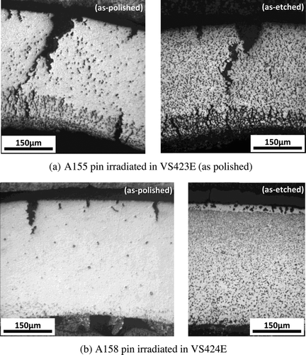
In addition, microstructure observations of the upper part of fuel column of ChS-68 fuel pins were carried out. Representative photographs are shown in . Precipitation of σ phase was observed in all eight ChS-68 fuel pins for which PIEs were conducted. No FCCI to at least 700 °C has been reported for application of vibro-packed fuel with U metal getter particles [Citation16], but significant grain boundary corrosion occurred at the cladding inner surface of all ChS-68 fuel pins irradiated in these irradiation tests. From these results, it was clear that the irradiation temperature exceeded 700 °C. Besides, a lot of large cracks were observed in the outer surface, and fuel pin failure also occurred with some ChS-68 fuel pins. Especially, it was clear that the damage at the inner and outer surfaces of the A155 pin irradiated in VS423E was larger. These results supported the irradiation temperature estimated by the modified 316 stainless steel tube temperature monitors. It was judged that the irradiation temperatures of the ODS cladding fuel pins were about 770 °C in VS423E and about 720 °C in VS424E.
4.2. Investigation into the cause of the anomalous irradiation behaviors
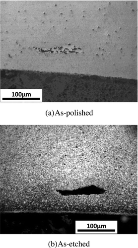
In the vicinity of the failure position of the X42 pin, the microstructure which suggested heterogeneity of material was observed and also abnormally coarse precipitations, which were judged to be M23C6 by the EPMA analysis, occurred as shown in Figure (c). These coarse precipitations were observed also in the upper part of the fuel column of the 9Cr-ODS cladding fuel pins (X43, X44) irradiated in VS423E together with the failed X42 pin as shown in . However, coarse precipitations were not confirmed at the position where irradiation temperature was low for the 9Cr-ODS cladding fuel pins irradiated in VS424E as shown in Figure . It was considered that the abnormally coarse precipitations were due to the high irradiation temperature based on these facts and the evaluation results of irradiation temperature mentioned above. And as shown in Figure , defects with a size of about 100 μm in the circumference direction and about 20 μm in the thickness direction were observed in some 9Cr-ODS cladding fuel pins. An ultrasonic testing was carried out for all ODS claddings provided to these irradiation tests as the manufacturing inspection. The ultrasonic testing calibration used a standard specimen having a micro-groove, 28 μm in depth, 30 μm in width and 2 mm in length, on inner and outer surface. However, those defects were not detected by ultrasonic testing. From these results, it seemed that those defects were thought to be metallic inclusions and there were similar defects in the failed X42 pin. It was considered that the material defects were highly possible causes of X42 pin failure, because fuel pin failure occurred only in one of the 9Cr-ODS cladding fuel pins and the heterogeneous microstructure was recognized in the vicinity of the failed position. As mentioned above, the cause of the anomalous irradiation behaviors which occurred in 9Cr-ODS cladding fuel pins irradiated in VS423E was judged as heterogeneity including manufacturing defects of 9Cr-ODS claddings provided to this irradiation test and the abnormalities of the irradiation temperature that reached a maximum of about 770 °C.
Figure 14 Optical micrographs of 9Cr-ODS cladding fuel pin (X44) irradiated in VS423E (top of fuel column; distance from core center = 213 mm)
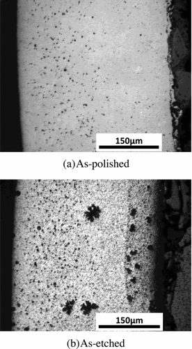
Figure 15 Material defect estimated to be metallic inclusion observed in 9Cr-ODS cladding fuel pin (X46)
On the other hand, the manufacturing defects considered to be the cause of such anomalous irradiation behaviors were not confirmed for the 12Cr-ODS cladding manufactured by the partial pre-alloy process. So, the pre-mix process, which was applied to the manufacturing of 9Cr-ODS claddings provided to these irradiation tests, was suspected as the cause of the heterogeneity of quality including defects and metallic inclusions. In fact, there is a report that the inclusions were observed in the ODS steels manufactured by the pre-mix process [Citation18]. The investigation to determine the cause of anomalous irradiation behaviors and the countermeasures to improve the quality will be reported in reference [Citation19].
5. Conclusion
The ODS cladding fuel pin irradiation tests done in BOR-60 provided irradiation results to burn-up of about 11.9 at% and neutron dose of about 51 dpa with the irradiation temperature over 700 °C. Valuable FCCI data were acquired which was one of the main objectives of the irradiation tests, and it was shown that FCCI could be reduced due to the lowered oxygen potential in the fuel pins using U metal getter, even in low Cr content cladding such as 9Cr-ODS. Valuable data indicating application prospects of the ODS claddings for high burn-up fuel were obtained regarding superior dimensional stability and integrity of the upper end-plug joined by the PRW method.
On the other hand, significant Cr depletion behavior was observed at the outer surface of the 9Cr-ODS claddings. Technical issues that should be solved in order to get practical use were identified from the results of tests; they were related to the fuel pin failure and the anomalous microstructure change in 9Cr-ODS cladding fuel pins irradiated in VS423E. As causes of the failure and the microstructure change, the following were proposed: the irradiation temperature reached around 770 °C and manufacturing defects were present which included metallic inclusions and the heterogeneous microstructure of 9Cr-ODS claddings.
Acknowledgements
The execution of these irradiation tests required the active cooperation of many people in the Japan Atomic Energy Agency (JAEA) and the Research Institute of Atomic Reactors (RIAR), and we wish to gratefully acknowledge their support and encouragement. In particular, we thank Mr. A.S. Korolkov, Mr. S.V. Kuzmin, Dr. V.A. Kisly, and Dr. S.V. Pavlov.
Notes
*1 Peak value of ODS cladding fuel pin.
*2 Calculated value based on actual performance of BOR-60 operation.
*1 Y2O3 = 1.27 × Y, *2 Ex. O = Total O-0.27 × Y.
*1 Effective full power days. *2 Maximum value of ODS cladding fuel pin, calculated value based on actual performance of BOR-60 operation.
References
- Shimakawa , Y , Kasai , S , Konomura , M and Toda , M . 2002 . An innovative concept of a sodium-cooled reactor to pursue high economic competitiveness . Nucl Technol , 140 : 1
- Ukai , S , Mizuta , S , Fujiwara , M , Okuda , T and Kobayashi , T . 2002 . Development of 9Cr-ODS martensitic steel claddings for fuel pins by means of ferrite to austenite phase transformation . J Nucl Sci Technol. , 39 ( 7 ) : 778
- Ukai , S , Okuda , T , Fujiwara , M , Kobayashi , T , Mizuta , S and Nakashima , H . 2002 . Characterization of high temperature creep properties in recrystallized 12Cr-ODS ferritic steel claddings . J Nucl Sci Technol. , 39 ( 8 ) : 872
- Ukai , S and Fujiwara , M . 2002 . Perspective of ODS alloys application in nuclear environments . J Nucl Mater. , 307–311 : 749
- Ukai , S , Kaito , T , Ohtsuka , S , Narita , T , Fujiwara , M and Kobayashi , T . 2003 . Production and properties of nano-scale oxide dispersion strengthened (ODS) 9Cr martensitic steel claddings . ISIJ Int. , 43 ( 12 ) : 2038
- Ohtsuka , S , Ukai , S , Fujiwara , M , Kaito , T and Narita , T . 2005 . Nano-structure control in ODS martensitic steels by means of selecting titanium and oxygen contents . J Phys Chem Solids. , 66 : 571
- Yoshitake , T , Abe , Y , Akasaka , N , Ohtsuka , S , Ukai , S and Kimura , A . 2004 . Ring-tensile properties of irradiated oxide dispersion strengthened ferritic/martensitic steel claddings . J Nucl Mater. , 329–333 : 342
- Yamashita , S , Yoshitake , T , Akasaka , N , Ukai , S and Kimura , A . 2005 . Mechanical behavior of oxide dispersion strengthened steels irradiated in Joyo . Mater Trans. , 46 ( 3 ) : 493
- Kaito , T , Ohtsuka , S , Inoue , M , Asayama , T , Uwaba , T , Mizuno , T , Ukai , S , Furukawa , T , Ito , C , Kagota , E , Kitamura , R , Aoyama , A and Inoue , T . 2009 . In-pile creep rupture properties of ODS ferritic steel claddings . J Nucl Mater. , 386–388 : 294
- Yano , Y , Ogawa , R , Yamashita , S , Ohtsuka , S , Kaito , T , Akasaka , N , Inoue , M , Yoshitake , T and Tanaka , K . 2011 . Effects of neutron irradiation on tensile properties of oxide dispersion strengthened (ODS) steel claddings . J Nucl Mater. , 419 : 305
- Ukai , S , Kaito , T , Seki , M , Mayorshin , A A and Shishalov , O V . 2005 . Oxide dispersion strengthened (ODS) fuel pins fabrication for BOR-60 irradiation test . J Nucl Sci Technol. , 42 ( 1 ) : 109
- Kaito , T , Ukai , S , Povstyanko , A V and Effimov , V N . 2009 . Fuel pin irradiation test at up to 5 at% burnup in BOR-60 for oxide-dispersion-strengthened ferritic steel claddings . J Nucl Sci Technol. , 46 ( 6 ) : 529
- Seki , M , Hirako , K , Kono , S , Kihara , Y , Kaito , T and Ukai , S . 2004 . Pressurized resistance welding technology development in 9Cr-ODS martensitic steels . J Nucl Mater. , 329–333 : 1534
- Porollo , S I , Konobeev , Y V and Garner , F A . 2009 . Swelling and microstructure of austenitic stainless steel ChS-68 CW after high dose neutron irradiation . J Nucl Mater. , 393 : 61
- Kashihara , H , Shikakura , S , Yokouchi , Y , Shibahara , I , Matsushima , H and Yamamoto , K . 1990 . “ Dimensional stability of FBR fuel pins with modified type 316 stainless steel cladding at high burn-up ” . In Proceedings of the International Conference on Fast Reactor Core and Fuel Structural Behaviour 243 Inverness , , UK 1990 June 4—6 [ISBN-10: 0727715666, ISBN-13: 978-0-7277-1566-1]
- Herbig , R , Rudolph , K , Lindau , B , Skiba , O V and Maershin , A A . 1993 . Vibrocompacted fuel for the liquid metal reactor BOR-60 . J Nucl Mater. , 204 : 93
- Mrowec , S. 1980 . Defects and diffusion in solids, an introduction. Material science monographs , Vol. 5 , PWN-Polish Scientific Publishers-Warszawa .
- Kasada , R , Lee , S G , Lee , J H , Omura , T , Zhang , C H , Dou , P , Isselin , J , Kimura , A , Inoue , M , Ukai , S , Ohnuki , S , Fujisawa , T , Okuda , T and Abe , F . 2009 . “ Super ODS steels R&D for fuel cladding of next generation nuclear systems 5) Mechanical properties and microstructure ” . In Proceeding of the International Conference on Advances in Nuclear Power Plants 2009 (ICAPP 2009) 2211 Tokyo , Japan 2009 May 10-14 [ISBN: 978-1-61738-608-4]
- Ohtsuka , S , Kaito , T , Yano , Y , Yamashita , S , Ogawa , R , Uwaba , T , Koyama , S and Tanaka , K . Investigation of the cause of peculiar irradiation behavior of 9Cr-ODS steel in BOR-60 irradiation test . J Nucl Sci Technol. , Forthcoming
