Abstract
An international joint project of fusion experimental reactor, the ITER (International Thermonuclear Experimental Reactor), is reviewed in view of long-range fusion energy research and development (R&D). Its purpose, goal, evolution, and the present construction status are briefly reviewed. While the ITER is a core machine in the present stage, generation of electricity is a role of the next-step fusion demonstration power plant “DEMO.” The status of designs and technology R&D for DEMO are also reviewed.
1. Introduction
Nuclear fusion is notable for its substantial advantages over other types of energy production in terms of abundant resources, safety, and environmental aspect. Worldwide long-term efforts in research and development (R&D) have been made and are still continuing toward practical utilization of fusion energy. Remarkable progress has been made in the past 40 years in generating, heating, and controlling very high-temperature plasmas and in developing machine technologies, yet there are still important issues to resolve before entering into construction of a power plant. To challenge and overcome these issues, a stage of experimental reactor is necessary as an intermediate step. Recognizing the importance of this step, yet knowing that large resources are required, the world's leading countries have decided to make this reactor through international collaboration, a joint program called “ITER” (International Thermonuclear Experimental Reactor). The present paper is intended to review the progress of fusion technology from the start of the ITER program to the preparation of DEMO reactors, the first electricity demonstration power plant. First, the authors intend to review the scientific and strategic role of ITER and how the ITER program has been started, evolved, and progressed internationally.
The intrinsic difference between ITER and the next-step DEMO is the tritium fuel supply. In ITER, tritium is supplied from external sources such as the CANDU reactor, while the DEMO has a tritium self-supply function through the tritium breeding blanket, which also converts the fusion neutron energy into the coolant heat, the source for driving turbines for electricity generation. Also, the DEMO is required to have a higher plasma performance. Thus, the DEMO has to be structured not as a simple extrapolation of ITER, but as integration of all the technical outcomes, of ITER, technological development on the blanket, and higher plasma performance.
2. Start of a big project ITER
2.1. General view toward power plant
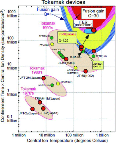
In 1980s, several large tokamak-type fusion machines had been built in United States, European Community (EC), Soviet Union, and Japan, and the performance of plasma was remarkably improved owing to the progress of machine fabrication technologies and the upgrade of relevant plasma heating systems, wherein the plasma was heated up to a sufficiently high temperature approaching a reactor-relevant collision-less state. The simplest figure of merit to express the fusion system performance is the energy multiplication factor, the so-called “Q value,” which is defined by a ratio of fusion power output to the external heating power injected into the plasma (). In general, higher Q values can be obtained with an increase in the product of plasma density (n), plasma temperature (T), and the plasma energy confinement time (τ). In the middle of 1980s, it was highly anticipated that achieving Q ∼ 1(breakeven), an important milestone for these large devices, was near at hand (). Actually, this milestone was successfully accomplished with the attainment of Q ∼ 0.65 [Citation1] in deuterium–tritium (DT) plasmas by the JET (EU), and equivalent Q ∼ 1 in deuterium–deuterium(DD) plasmas by the JET and by the JT-60 (Japan) [Citation2]. The plasma temperature achieved is relevant to fusion power reactors (up to 40 keV), as can be seen from Figure . However, from a system study of the power plant, the Q values of 30–50 are necessary, meaning that much dense and better-confined plasmas are necessary [Citation3].
Figure 1 Tokamak-type fusion power plant concept and the definition of energy multiplication factor Q
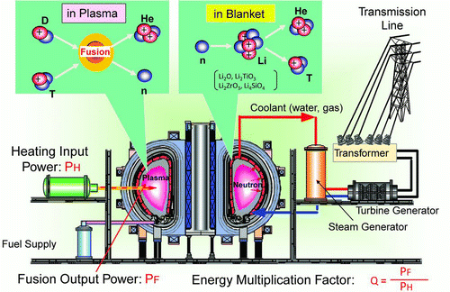
Figure 2 Progress of the plasma performance toward fusion reactors in the nτ– T diagram, where n is plasma ion density, τ is energy confinement time, and T is ion temperature
As long as the plasma is magnetically confined, the energy confinement property is determined by the energy transport process. Therefore, a larger machine would be expected to provide a better confinement property and hence give higher Q values. However, what is unknown until now for the existing fusion devices is the consequence of significant burning. When the DT fusion reaction takes place, 20% of the fusion energy is born by the produced ash α-particles, which in turn interact with background plasma and affect the plasma temperature, density, and current profiles [Citation4]. Namely, when the α-particle power becomes significant, the plasma may determine its own profiles, a characteristic called as “self-organization.” This situation is significantly different from the nonburning plasma where the plasma profiles are determined by the deposited heating power from external sources. Thus, the need for the experimental reactor from the plasma aspect as an intermediate step is to study and obtain sufficient knowledge of controlling highly burning, self-organizing plasma before entering into the power plant phase. The mission of Q ≥ 10 in ITER [Citation5, Citation6] is determined for such plasmas where the produced α-particle power is greater than the externally injected power at least by a factor of 2.
2.2. Prelude of the ITER program “INTOR Activity”
Any big program cannot start without preceding technical works. In the1980s, how to design next-step (experimental) machines had not been clear yet and was an important issue. The activity called “INTOR” (International Tokamak Reactor activity), carried out under the auspices of the International Atomic Energy Agency (IAEA), had played a substantial role in searching and studying how to design fusion reactors. The INTOR started in 1978 and continued until 1985 () [Citation7]. Several types of reactor concepts developed in domestic countries were brought into periodically held INTOR workshops. The obtained knowledge was brought back to their countries, intended to be applied for their domestic programs.
However, no country had sufficient enthusiasm or financial power to start construction of the experimental reactor as its own domestic program or even as an international program. Thus, the INTOR activity did not lead to its construction, but provided a methodology on how to design reactors, and gave a sound basis of starting the ITER program that followed.
2.3. Political initiative
The origin of the ITER project was triggered by the political initiative, the joint communique between R. Reagan of the Unites States and M. Gorbachev of the USSR (now the Russian Federation) at the Geneva Summit Meeting in 1985. As a symbol of termination of the “Cold War,” they proposed to undertake an international project aimed at developing fusion energy for peaceful purposes. The EC and the Government of Japan were invited to join the project, and these four parties agreed to start joint activities on fusion experimental reactor ITER. What was different from the preceding INTOR activity was that the ITER clearly tried to develop one single design aiming at its construction, although the fusion strategy of each party still lay on the domestic program in those days.
2.4. Start of the ITER program as preparation for construction
Before the start of construction, a series of activities were carried out. The first step was the Conceptual Design Activities (CDA; 1988–1990), followed by the Engineering Design Activities (EDA; 1992–2001). Since the governmental commitments were made step by step, it was necessary to build an agreement at each step (Figure ).
The CDA was started in May 1988 under the auspices of the IAEA. The objective of the ITER was to demonstrate how to control significantly burning plasmas and to test major components of fusion reactors in a nuclear environment [Citation8].
With the progress of the program, the scale of these activities had to be enlarged. The aim of the EDA was to produce a detailed integrated engineering design of ITER and all technical data for decisions on the construction. For this purpose, the ITER Director led the Joint Central Team and integrated the design work. The domestic team in each party shared a part of the design work and implemented technology R&Ds. These activities were shared on an equal committal basis, and the project tools such as work program and task agreement were developed. In the following subsections, the authors try to show how the ITER project evolved from the beginning.
2.4.1. Structure of the technical work
shows a comparison of the structure of the technical work of the CDA and EDA. In the EDA, the working site was distributed into three sites but the technical work was integrated under the strong leadership of the Director [Citation9].
Table 1 Typical machine parameters of the ITER-CDA, ITER-FDR, and ITER-FEAT
2.4.2. Obtained physics and technological basis
In the CDA, a conceptual design of ITER was timely documented as a basis for entering the EDA [Citation8]. In the EDA, in addition to the engineering designs of the ITER, the physics and technology basis was also firmly developed. As physics R&D, seven expert groups related to major physics issues were organized voluntarily in 1994 among the world institutes and their experimental research efforts were concentrated to provide necessary data for the machine design [Citation5].
The technological basis for ITER was substantially developed in the EDA. In the area of reactor technology, the R&D activities were conducted by the cooperation of the four parties in order to provide design database and to confirm technical integrity of the ITER design.
2.4.3. Overall design
The design of ITER changed with time mainly due to update in the physics and technology database. In the CDA design, the ITER was a relatively small, double-null cross-section [Citation8]. At the start of the EDA, the CDA design was regarded to have a large risk to achieve the ITER mission. The ITER Director P.H. Rebut led the team to design a small-risk machine, a larger-size design (R = 8.1m) (Table ). However, this design ITER-FDR (1998) [Citation10], completed at the end of the originally planned 6-year period EDA, was regarded to be too large from a financial point of view. The parties decided to seek a compact design with a target construction cost of about a half, and requested a design modification by extending the EDA period for three more years. Thus, a detailed engineering design (ITER-FEAT R = 6.2 m) was carried out in 2001. The total delivery of the design report amounted to 30,000 pages, including engineering design, safety analysis, and cost estimate [Citation11].
2.5. Technical aspect of ITER
2.5.1. Technical objectives
After the process of preparatory design work, the ITER EDA-FEAT was ultimately judged to satisfy the technical objectives, and now constitutes the dimensions and performance of the present ITER [Citation11]:
Plasma performance: | |||||
– Achieve extended burn-in inductive current operation with Q⩾10, with a duration between 300 s and 500 s, at average neutron wall load ⩾0.5 MW m−2 and a fluence ⩾0.3 MWa m−2. | |||||
– Aim at demonstrating steady-state operation through noninductive current drive at Q⩾5. | |||||
Engineering performance and testing: | |||||
– Demonstrate availability and integration of essential fusion technologies. | |||||
– Test components for a fusion reactor. | |||||
– Test tritium breeding blanket module that would lead to tritium self-supply in future reactors. | |||||
2.5.2. Design feature
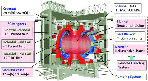
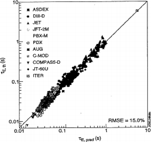
Machine parameters were chosen to provide confidence in achieving the required plasma and engineering performance. In particular, the ITER machine size was determined on the basis of a reliable empirical scaling law by the world tokamaks of energy confinement time of ELMy-H-mode, as shown in [Citation12–Citation14]. shows a bird's eye view of the ITER machine and typical roles and dimensions. Distinguished features of the ITER from the previous large tokamaks are referred in the subsequent subsection.
Figure 4 Empirical scaling law obtained by the collaboration of the integrated work done by the ITPA (ITER Physics Activity) group
2.5.2.1. Mode of operation
In tokamaks, toroidal current flowing in the plasma is essential for plasma confinement. The ITER machine is designed to operate in two different modes. The main mode is a pulsed operation mode that utilizes induction of the plasma current by the superconducting coils. A high plasma current is easily obtained, but the duration of the current at 15 MA is limited to about 400–500 s due to a capacity of the magnetic flux generated by these superconducting coils. The exploration of Q ≥ 10 will be done in this pulsed mode. The second mode of operation is a steady-state operation where the plasma current, lower than the pulsed mode, is driven by a momentum injection by the external current driver such as a neutral beam injection (NBI) or radiofrequency (RF) injection. The current drive efficiencies by these methods are not attractive, but fortunately, a significant amount (50–80%) of the current is driven by a gradient of high pressure plasma by itself [Citation4]. Therefore, the required current driven by external sources can be limited at a modest level. For this mode of operation, ITER is designed up to 1000-s operation, a time sufficiently longer than the current diffusion time and the particle equilibrium time. There is an intermediate mode of operation called hybrid operation. Most of the test blanket module (TBM) tests to be described later will be made by the hybrid mode or by the steady-state mode.
2.5.2.2. Tokamak assembly container
The tokamak core machine is assembled in a large vessel called cryostat and is pumped to a vacuum state to prevent conduction and radiation heat load to the superconducting magnets. The cryostat is made of reinforced stainless steel, with a single-shell cylinder structure 24 m high, 28 m wide and with flat ends. It is housed in a cylindrical concrete bioshield.
2.5.2.3. Magnet system
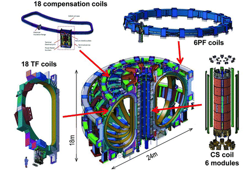
All the coils for the ITER are made of superconducting materials. Two different technologies are necessary for the ITER superconducting magnets (). Toroidal field (TF) coils generate a strong but steady-state magnetic field, and the central solenoid (CS) and poloidal field (PF) coils generate a time-dependent magnetic field for driving plasma current or for plasma position control or shaping. As superconducting materials, the Nb3Sn generates the highest magnetic field and the NbTi is used for lower magnetic field coils.
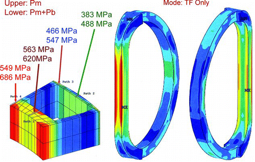
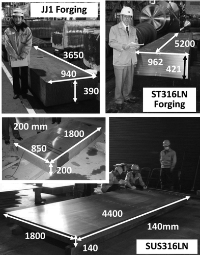
The TF superconducting magnet system consists of 18 coils, and each coil contains a circular conductor, composed of Nb3Sn strands, embedded in grooved structural radial plates to form winding packs. These winding packs are housed in a thick steel casing. Very high stresses due to huge electromagnetic forces () require dedicated materials (JJ1, SS316LN, etc.) tolerable against these stresses at cryogenic temperature to be employed. The CS coil is composed of six modules stacked vertically and are energized separately (Figure ). The six PF coils have different dimensions but are designed using NbTi conductor in double pancake windings. The 18 NbTi saddle-shaped small correction coils outside the TF coils are mounted to compensate field errors due to manufacturing inaccuracy or misalignments of coils during assembly, as well as to control plasma instability (resistive wall mode). summarizes the required main coil specifications and the corresponding selected superconducting materials.
Table 2 Major parameters of the ITER superconducting magnet system
2.5.2.4. Vacuum vessel
Because of the topological relation of the vacuum vessel with the TF coils, the vacuum vessel consisting of nine toroidal sectors has to be joined by onsite welding. Each vessel sector is a double-walled stainless steel structure welded to form a ribbed shell structure, with internal neutron radiation shield plates and ferromagnetic inserts to reduce TF ripple. There are 18 equatorial ports for the RF heating antennas, NBI ducts, TBMs, plasma limiters, and for diagnostics. Some of these ports are used for the remote replacement of blanket modules. The lower and the upper ports accommodate cryopumps, diagnostics, glow discharge and cleaning system, pellet injection, electron cyclotron antennas, and in-vessel viewing system. These ports are also used for remote replacement of the divertor cassettes.
2.5.2.5. In-vessel components and plasma-facing components
About 420 neutron shielding blanket modules (typical size is 1.4 m × 2.0 m wide and 0.8 m deep) in total have a single-curvature faceted beryllium-coated first wall, and are mechanically attached to the vacuum vessel through 3-cm diameter access holes for the connection bolts from the first wall front. The divertor consists of 54 cassettes (each 3.4 mL × 1.5 mW × 2 mH, 8 tons). The design heat flux is 5–10 MW m−2 (3000 cycles) for normal operations, but for abnormal transient events, a heat flux of 20 MW m−2, 10 s, 300 cycles has to be taken into the design. High heat flux elements are made of a carbon or tungsten joint with a copper alloy heat sink block with a cooling tube inside. The copper alloy is then joined with the stainless steel structure, which is fixed to the cassette body.
2.5.2.6. Heating/current drive system
Three kinds of heating systems are adopted in the ITER. The expected power to the plasma is 33 MW at 1 MeV by the NBI system, 20 MW, 170GHz by the electron cyclotron (EC) system, and 20 MW, 40–55 MHz by the ion cyclotron (IC) system. The NBI and EC systems will be also used for plasma current drive. In particular, these functions are essential for the steady-state operation.
2.5.3. Technological basis
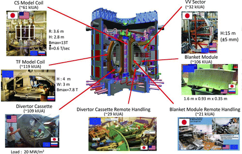
A systematic technology R&D program was implemented during the EDA to provide firm technical basis for the ITER design and to start construction of the ITER. These R&Ds include not only component technologies for the reactor core, but also peripheral subsystem technologies such as a heating/current drive system, remote maintenance, tritium handling, fuel injection and pumping, diagnostics, and safety-related technologies. Among them, seven large R&D projects were carried out on a scale not foreseen in the past, a scale that is prototypical or extrapolated to the ITER itself. These R&Ds were selected among the areas of superconducting magnet, vacuum vessel, blanket, divertor, and remote handling technologies (). In addition, these R&D programs [Citation11,Citation15] covered most of other medium- or small-scale key components.
However, due to limited resources and time, the R&Ds on some components or subsystems such as heating systems and diagnostic systems were not fully included in the EDA R&D program. These subsystems were planned to be installed into the ITER machine in the later phase of the ITER construction so that even though the R&Ds continued into the construction phase, the results of the R&D will be reflected in the fabrication of subsystems for the ITER. Now, the technological bases for the main components are reviewed hereafter.
2.5.3.1. Superconducting magnet
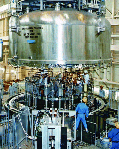
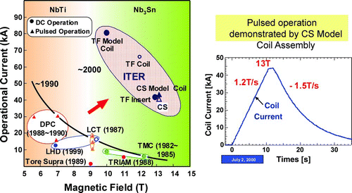
The ITER CS and TF model coil projects in the ITER EDA were intended to drive the development of the ITER full-scale conductor, including manufacturing of superconducting strand, cable, conduit, and termination. The R&D on the conductor in relation to AC losses, stability, and their joints was also done. These projects also integrate the supporting R&D programs on the total coil manufacturing technologies, including electrical insulation, winding processes, and quality assurance. The CS model coil is composed of two coaxial coil modules, an inner module and an outer module of roughly equal weight. A total of 29 tons of Nb3Sn strands, from seven different suppliers throughout the four parties, were fabricated and qualified. By using about 25 tons of the strands, the inner module and the outer module coils hosted by the United States and Japan,respectively, were fabricated and assembled in the ITER-dedicated test facility () at the Japan Atomic Energy Research Institute (JAERI). The size of the CS model coil (3.6 m wide, 2 m high) is almost the same as one module of the six coils of the ITER. The coil was tested at the ITER operating current of 46 kA (13 T), the same as the ITER operation. The stored energy was as high as 640 MJ. In addition, pulsed operation at a charging rate of 1.2 T s−1 from 0 T to 13 T and cyclic operation of 10,000 cycles were also performed.
The TF model coil consists of five racetrack-shaped double pancake wounds with a Nb3Sn circular conductor embedded in machined grooves of a radial structural plate. The coil was installed in the test facility in FZK, Karlsruhe, Germany, and energized up to 80 kA well above the ITER specification.
Both CS and TF model coils have shown a significant breakthrough in the superconducting magnet technology, as shown in .
2.5.3.2. Vacuum vessel
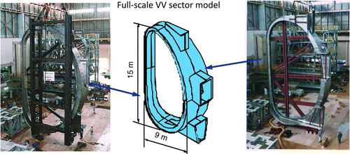
In order to reduce electrical conductivity while keeping structural integrity, the vacuum vessel of the ITER has a double-wall structure. The major objective of the Vacuum Vessel Sector Project is to obtain fabrication technologies for the ITER vacuum vessel by making a stainless steel (316 N) full-scale sector. Key technologies such as welding and control of welding distortion (the required tolerance of 20 mm) have been established by fabricating and joining two full-scale, 10-m-wide and 15-m-high segments (half-sectors) produced by different vendors. This was done by the field joint welding, and was confirmed satisfactory within a required tolerance of 5 mm ().
2.5.3.3. Divertor
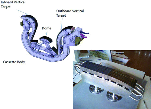
The divertor is one of the key components of the magnetic fusion machine, because it is exposed to a high heat flux of the scrape-off plasma. In the normal operation at Q ∼ 10, the heat flux to the divertor plates is estimated to be as high as 10 MWm−2 in steady state and 20 MW for short transient pulses. In the EDA, various elements for high heat flux components were developed and fabricated by the four parties. High heat cycle tests showed that carbon fiber composite (CFC) monoblock survived 2000 cycles at 20 MW and the tungsten armors survived 15 MWm−2 for 1000 cycles without degradation of the thermal performance [Citation16–Citation18]. The structural housing named “divertor cassette” was also fabricated with a required tolerance and was confirmed to withstand the thermal and mechanical loads to be imposed during ITER normal operation and transients. Remaining issues were to achieve high reliability of fabrication, because any defect in the joint of the heat sink to the parallel cooling tubes would be a problem as a whole ().
2.5.3.4. Shield blanket
The purpose of the ITER shield blanket is to shield neutrons and remove the generated heat by the cooling water but it has no tritium breeding function. Therefore, the ITER shield blanket module is much simpler than the DEMO tritium breeding blanket. However, in the plasma-facing shallow region of the blanket, the plasma–wall interactions, the neutron radiation, and heat removal can be simulated to those of DEMO's even though the neutron flux is much less than DEMO and the structure of the first wall requires development of advanced technologies for fabrication. In the EDA, a blanket module project was carried out to develop manufacturing technologies. Among them the hot isostatic pressing (HIP) and other advanced techniques to bond different materials such as Be-Cu and Cu-stainless steel have been developed and optimized for joining triplex first-wall structure.
2.5.3.5. Remote maintenance
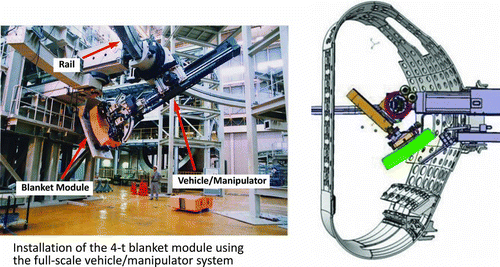
The ITER in-vessel components such as divertor cassettes or blanket modules are the subject of remote maintenance. The blanket remote handling system aimed to demonstrate remote replacement of a 4-ton ITER blanket module within a positional accuracy of ±0.25 mm. A manipulator system mounted on a vehicle can move along the toroidal direction on a closed rail deployed along the center of the vacuum vessel. A full-scale manipulator vehicle system was fabricated and mounted on a partial rail and tested in the JAERI platform in Japan to handle a 4-ton dummy blanket module successfully ().
Figure 13 Design concept (right) and R&D (left) of the blanket remote maintenance equipment. Photos provided by ITER Organization
The remote handling system for the divertor maintenance was also developed. The ITER divertor cassettes are removed remotely from the vacuum vessel and are transferred to the hot cell, where they are refurbished. A full-scale prototype equipment and facility was built and then tested at the ENEA Research Center of Brasimone in Italy.
2.5.3.6. Plasma heating systems
R&D for heating systems started in the EDA and continued to the ITER construction phase. Most of the efforts focused on the NBI system and the EC system. In the NBI system, an injection of 33 MW at 1 MeV is requested by using two NBI units. The unit performance will be achieved by the neutralization of a 40-A negatively charged deuterium beam obtained by a static accelerator, but it requires a long-range intense R&D. The target specification for one unit is 200 Am−2D−1 beam at 1000 keV, while the present achievement is 185 Am−2 H−1 beam at 980 keV by a reduced-size 5-stage accelerator [Citation19, Citation20]. Since there were no test facilities to test such full current at the rated power, a high energy but small current, and a high current with lower energy approaches were considered in parallel. For the integrated testing, an ion source of real size is planned to be fabricated as one of the construction phase R&Ds and will be tested at the test facility to be constructed in Italy before installation in the ITER.
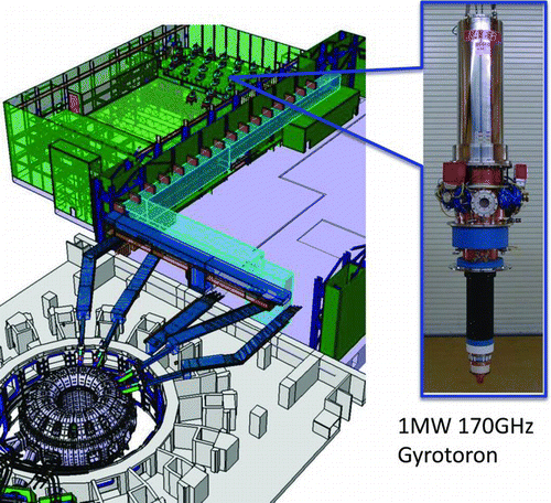
In the field of RF heating, a 170-GHz gyrotron oscillator tube has been developed and has demonstrated successful extraction of 1 MW RF power for 800 s (see ). The conversion power efficiency was as high as 55%. In addition, a dual-frequency (170 GHz and 137 GHz) gyrotron has been developed to increase flexibility of plasma heating. A compact transmission waveguide (1 MW per line) and mirrors have also been developed [Citation21].
2.5.3.7. Other R&Ds
In addition, the development of components for fuel injection, pumping, tritium processing, power supplies, and plasma diagnostics, as well as safety-related R&D, were carried out and contributed to start procurement for the ITER.
2.6. Start of ITER Construction
2.6.1. ITER site negotiations
Following the completion of the EDA, the four parties (EU, Japan, the Russian federation, and Canada) launched the intergovernmental negotiations in November 2001. The first aim was to draft a Joint Implementation Agreement for the ITER construction, operation, exploitation, and decommissioning activities. Important issues for negotiation included finalization of the requirements for the ITER construction site, function of the ITER legal entity and the roles of director general and his/her deputies and their selection criteria, and how to make sharing of various ITER components and subsystems possible.
Four potential ITER sites were proposed by the parties; Clarington in Canada, Vandellos in Spain, Cadarache in France, and Rokkasyo in Japan. These candidate sites were assessed satisfactory by the expert team against the ITER site requirements.
2.6.2. Sharing of the work
In parallel to site negotiation, the parties discussed how to share the tasks for construction of the ITER. It was agreed to share responsibilities equally through the in-kind contribution for the component procurements except for the host party, which may have miscellaneous benefits. Each component of the ITER machine and facilities had been evaluated in the extended EDA phase in terms of value (by the ITER unit of account). However, the sharing of the components was not easy, because every party wished to share the advanced technology such as superconducting magnet, in-vessel components, etc. However, trying to seek equality too strongly would cause division of components into many small pieces and will lead to technical interface difficulties. Another concern was that there were only a few vendors that had the experience of fabricating ITER R&D components in the EDA phase. Therefore, the allocation of tasks was made through the overall consideration of technical competency, taking account of the past experience or similar one, and less interface troubles under the condition of total equal share (total value). For the in-kind contribution, the resources for procurement of components are born by the party, not by the ITER organization. The tasks such as integral design and the machine assembly at the site are allocated to the ITER organization and the resource for such tasks is born by the cash contribution from the parties, similar to the joint fund for operation of the ITER joint team.
2.6.3. Seven parties’ participation
When the discussion on the construction of the ITER started, the United States, once leaving the ITER activities after the end of the initially scheduled EDA in 1998, returned to the ITER for the ITER construction activities. Subsequently, China and the Korea showed their willingness to participate in the ITER, and a little later, India participated. As a result, in total, seven parties (EU, Russia, Japan, the United States, China, Korea, and India) participated. It means that more than half of the world population belongs to the ITER member countries. The ITER has thus become a truly worldwide international joint project aiming at ultimate source of energy for humankind.
As a result of long-lasting negotiations by the parties, it was agreed in June 2005 in Moscow that the construction site should be in Europe, at Cadarache, Saint-Paul-Lez- Durance, in France. The host party shares about 45% of the total construction values and the other participating parties share equally about 9% of the total.
While the ITER is a big step in the fusion energy research scenario, it does not mean to cover all the necessary R&D elements for the next-step power plant DEMO. At the time of ITER construction site decision, the EU and Japan agreed to implement jointly in the territory of Japan the complementary activities of ITER, which are called “Broader Approach Activities” [Citation22].
2.7. Status of the ITER construction
The ITER construction activities formally started in October 2007 after the process of ratification of the ITER Agreement by all the parties. A set of ITER Agreement and relevant declaration materials define the purpose and goal of the project, a central regal entity and its organization, estimated total project cost (in terms of ITER value) and allocation of the in-kind and cash contributions for the construction phase, and contributions for the operation and decommissioning phases as well.
2.7.1. Build-up of organization
The ITER Agreement defines an establishment of the international entity named ITER Organization (IO). Mr K. Ikeda was nominated as the first Director General. Then, he immediately tried to build up the team through recruitment of the staff. Because of the in-kind concept, the ITER agreement also defines the role and responsibility of the parties. Namely, for carrying out the in-kind contribution, each party nominates a regal entity (Domestic Agency, DA) for implementation of the responsibility. The number of staffs of the IO has increased rapidly, and as of the end of July 2012, it has reached a total of 472 [Citation23]. By 2010, the start-up of the ITER construction phase was successfully over with the completion of the baseline design documents. At this time, a new Director General was appointed, Prof. O. Motojima, and the project shifted to the substantial procurement and fabrication phase.
2.7.2. Schedule
The initial reference project schedule was attached to the ITER Agreement as a relevant document, but due to the time-consuming build-up of the IO, a time for finalization of the component designs, etc., there were some initial delays in the project schedule. However, the procurement agreement between the IO and the DA clearly defined the component specifications to be procured and fabricated by each party, now reaching about 80% of the total tasks in terms of their value [Citation23]. The other important measure is the licensing process of the ITER as a nuclear facility. The IO's proposal on the ITER is judged to fulfill the safety requirements, and now the IO has been authorized to create the ITER facility by the French nuclear regulatory authorities, ANS. Thus, one of the important milestones has been accomplished [Citation24].
The project schedule as of 2011 incorporated an integral commissioning scenario toward the goal of the ITER first mission (Q ∼ 10). The first plasma will be fired in 2020, with a limited number of in-vessel components to test basic elements such as the vacuum vessel, superconducting magnet, and divertor. Then, the in-vessel components and heating systems will be installed to operate for hydrogen plasma and DD plasma successively. After confirmation of the machine integrity in these non-DT phases, the tritium fuel will be introduced and high-power heating by the NBI and the RF heating system has been planned to generate a higher fusion energy output, approaching its mission of Q ∼ 10.
Once this mission is achieved, the ITER will then try to operate longer pulses and demonstrate quasi-steady-state operation but at somewhat lower levels of Q value (Q ∼ 5). This advanced plasma operation can be done by a combination of the self-induced plasma current (bootstrap current) and the externally driven current from the heating/current drive systems. This mode of operation as well as the hybrid mode operation will be used for testing the TBM.
2.7.3. Status of component fabrication and construction
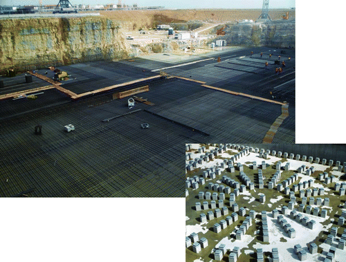
The ITER construction site was provided by the host party and the ground smoothing and leveling works went on until May 2011. Then, the construction work on high-priority buildings started. and show the present status of the Cadarache ITER site. The onsite PF coil assembly building has been completed, and the central ITER office building is near completion. The construction of the Tokamak complex building, the largest one in the site, started with the grounding work, as shown in Figure . About 500 antiseismic bearing structures have been installed in the pit, which will support the base floor of the Tokamak hall to mitigate earthquake acceleration.
Figure 15 ITER main office building near completion and the working area in the completed PF coil assembly building (photos provided by ITER Organization)
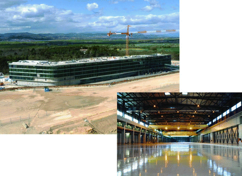
Figure 16 The groundwork for the Tokamak complex building is in progress and about 500 antiseismic bearing structures have been installed in the pit (photos provided by ITER Organization)
In the case of component procurement, the superconducting coils have been the first priority. The Nb3Sn superconducting strands have been fabricated by the vendors (China, Europe, Japan, Korea, Russia, and the United States), about 330 tons in total by July 2012, 75% against the required amount for TF coils, and the conductors for six TF coils out of 18 coils have been produced. shows a schematic view as to how the cable in the conduit conductor is made from the superconducting strands. Cabling of the strands and their formation into the conductor is in progress. The vendor has made a straight jacketing process line of around 1 km () to insert the superconducting cable into the steel conduit in Japanese works in Fukuoka with the processed conductors on the bobbin. Similar lines have been made by several parties that share task of conductor fabrication. These conductors will then be wound in the same shape as the final coils. shows a TF conductor winding line at the ASG Superconductors (EU) showing the first full-size turn for demonstration. In the next step, the shaped winding pack will be installed in a huge oven and kept for a few hundred hours at high temperature (∼700°C). After this process, the conductor achieves a real superconducting property.
Figure 17 ITER cable in conduit conductors. Note: The superconducting cable is inserted in a metal conduit whose outer shape is rectangular (for CS and PF) or circular (for TF). Several hundreds of strands, each containing about 10,000 Nb filaments of a few micrometers, are twisted and pulled in a metal conduit of about 3 cm diameter
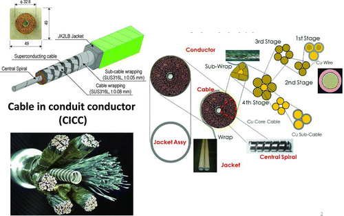
Figure 18 Superconducting cable fabrication facility at the Shin-Nittetsu Engineering Works and the produced conductors wound on a bobbin (lower photos)
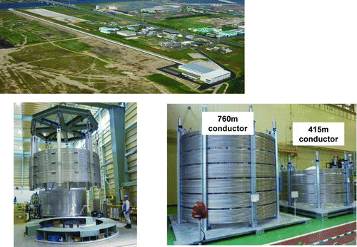
Figure 19 TF conductor winding line at the European vendor ASG Superconductors showing a first full-size turn for demonstration (ASG Superconductors copyright)
For the thick TF coil casing, trial mass production of high-stress-tolerant cryogenic steel was done in one of the steel industries. This special metal will be used at the high-stress part of the coil casing ().
Figure 20 Trial fabrication of the TF coil casing steel block. Note: The JJ1, ST316LN, and SS316LN are developed for high performance at cryogenic temperatures
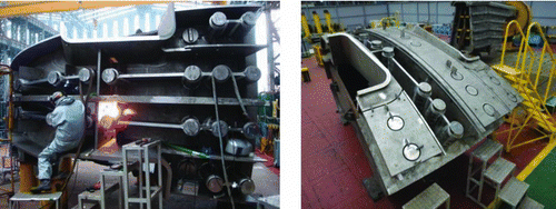
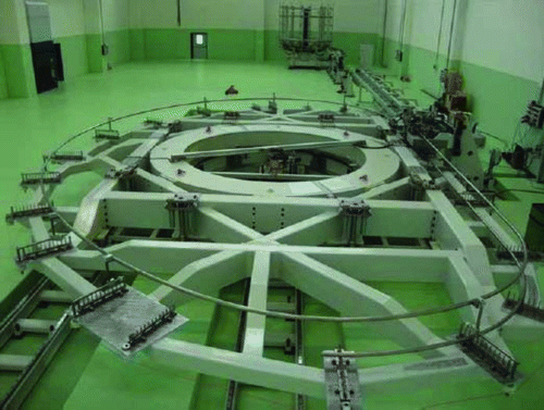
For the double-wall vacuum vessel requiring a high accuracy, mock-up fabrications have been made in the Korean heavy industry ().
3. Mission of the DEMO reactors and strategy toward commercial reactors
3.1. Possible mission of DEMO
Until the latter half of 1990s, before the start of discussion on the ITER construction site, in-depth discussion had not been made at the government level on the approach toward commercial fusion reactors. However, it was commonly anticipated that the next-step reactor following ITER would be the one that demonstrates electricity production in a plant level. This was called DEMO. However, it was questioned whether it will be necessary to have one more step (called PROTO) after DEMO before commercialization. Also, whether a period of time was needed before the first-generation commercial reactors were available had not been clear yet. At the beginning of the 2000s in Europe, encouraged by the ITER construction discussion, a question was raised at the political level on what kind of approach should be taken to realize fusion energy within 30 years, an area of interest for politicians and public. The scientific side responded that the program could be accelerated if the test facilities for fusion materials development, in particular, IFMIF [Citation25], would be built in parallel to ITER, and that DEMO and PROTO generations could be combined into a single step. This is called “A Fast Track Approach” [Citation26].
However, the reactor design study suggested that a simple extrapolation from the ITER plasma may not be sufficient to provide an attractive power plant. In order to obtain a high-Q reactor, either the plasma pressure (nT) or the plasma confinement performance (τ) should be bigger than that of ITER. This means that if we want to keep the machine size of DEMO comparable to that of ITER, the plasma pressure must be higher than that of ITER. This approach, often called as advanced plasma research, is relevant to the DEMO and has to be encouraged in parallel to ITER. In this direction in Japan, the national program on fusion established in 1992 by the Atomic Energy Commission was revisited in the early 2000s for check and review. It was stated that role of PROTO could be combined with DEMO and stressed that “the advanced plasma research” leading to DEMO operation and that “the development of materials for the first wall, blanket, and divetor” should be pursued intensively in addition to ITER ().
Figure 22 Integration of elements toward DEMO reactor. Note: The ITER integrates most of the plasma physics and technologies, but the blanket technologies and the advanced plasma development have to be incorporated into DEMO reactors
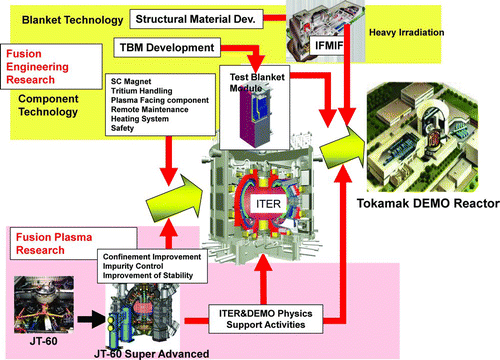
In these programs, it has become a common view that DEMO would be the last integrated R&D device before the first-generation commercial reactors become available.
Once DEMO is defined as above, its fundamental role and mission becomes clearer. The DEMO should integrate all necessary components for the fusion reactor and demonstrate electricity production with adequate perspectives on reliability, maintainability, and availability. It should be also preferred to provide the opportunity for qualification of components required by the first-generation commercial reactors [Citation27].
3.2. Toward commercial reactors
Precisely, the DEMO is the first integrated reactor that incorporates all the plasma physics and component technologies needed for power plant. For this purpose, the DEMO should have machine flexibility or redundancy (it is not optimized). Therefore, once the optimum operation mode for continued electricity generation is established, the system margins kept in the performance of each component shall be effectively cut for simplification and for cost savings. In addition, similarly to other power plant, it is likely that there will be still component-level improvements seeking for higher reliability and availability and for cost saving to be continued into the commercial reactors. In other words, the first-generation commercial reactors should incorporate experiences of integrated DEMO construction, operation, and the component-level improvement as well. Design and testing codes and standards for quality analysis as well as for licensing purpose have to be established in the DEMO stage. Thus, the DEMO stage activities will provide a feasible road map toward first-generation commercial reactors.
4. Status of the DEMO reactor system study
Preliminary design studies of DEMO reactors have been performed by several groups in a fusion thermal output range of 1500–5000 MW [Citation28–Citation32]. Key elements so far learned from these studies are the dense and stable plasma, the tritium breeding blanket system, scheduled maintenance scenario of the in-vessel components such as blanket modules and diverters keeping a reasonable availability [Citation32, Citation33].
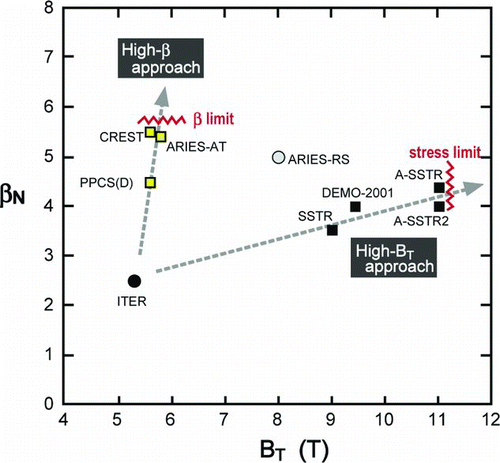
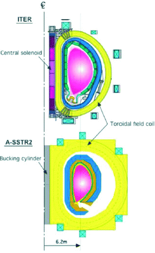
The fusion power density is proportional to β2 N B 2 T, where βN is a normalized plasma pressure (=β(\%)aB T I − 1 P), B T is the magnetic field strength of the TF at the plasma axis, a is plasma minor radius, and I P is the plasma current. There were two approaches in the reactor design to achieve a high fusion power density, either by seeking a high βN or by seeking a higher magnetic field B T. In the 1990s and thereafter, efforts have been made in the reactor design by either of these approaches to achieve economically attractive designs. shows representative reactor designs made in the world. The high magnetic field approach was adopted in the design of A-SSTR [Citation34], A-SSTR-2 [Citation35], DEMO-2001 [Citation36], where B max is 23 T in the case of A-SSTR-2. The other high βN approach was taken in the design of reactors such as CREST [Citation37], ARIES-AT [Citation38], and PPCS Model-D [Citation39]. The magnetic field at the plasma is less than about 6 T [which means that the maximum field at the coil (B max) is less than about 13T]. These reactors try to operate close to a maximum plasma pressure (βN limit) by optimizing plasma profiles. The design of ARIES-RS [Citation40] is in between the two approaches, with βN=4.8 and B max = 16 T. shows a comparison of typical parameters of these reactors. In taking the high magnetic field approach, the stress in the magnet becomes huge, and so the structural materials packing the coils must be thick. For instance, shows a comparison between the ITER and the A-SSTR2, an end machine made using the high magnetic field approach. In the A-SSTR2, the maximum field is assumed to be 23 T by using high-temperature superconducting material Bi-2212. The A-SSTR2 generates 4 GW of thermal output despite the same major radius as that of ITER. As recognized in Section 2.5.2, to
Table 3 Comparison of fusion reactors aiming at high-power output densities
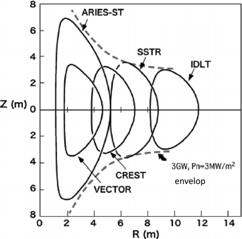
The high βN approach on the other hand can be realized by the low aspect ratio (R/a) machine. To generate the same fusion power, the size of a low aspect ratio machine is smaller than a high aspect ratio machine. An extreme design in the superconducting tokamak was represented by the VECTOR [Citation41], which has no central solenoid coil and no tritium breeding blanket in the in-board side wall. However, a small machine with a large fusion output means a high neutron wall loading density, so that the difficulty is shifted to the design of the blanket. shows cross-sections of typical designs of the same output of 3 GW and the envelop line for the neutron wall loading of 3 MWm−2. A compact machine like VECTOR whose cross-section is smaller than the envelop line is subject to a higher neutron wall loading than 3 MWm−2.
Figure 25 Cross-section of the plasma in the typical designs with an envelop of an output of 3 GW and a neutron wall loading of 3 MWm−2
Another issue of the DEMO and future fusion reactors is the design of the tritium breeding blanket and their maintenance. Several types of blanket concept have been proposed by a combination of solid compound or liquid lithium (Li) and the type of coolant [water or helium (He) gas or liquid metal]. Typical basic concepts are seen in the proposed TBM in ITER in . Thus, even though the plasma shape is the same, the choice of the blanket type will bring quite a different design and the maintenance scenario as an energy system. One of the design issues for most types of the blanket is the property of the structural material against neutron irradiation. The material should have good high-temperature characteristics, should be tolerant against high neutron fluence, and should be preferably of low activation. However, the irradiation database by the high flux neutrons is still insufficient for system design due to a lack of integrated time for irradiation tests and a lack of irradiation facilities. Therefore, it is necessary to encourage more R&D efforts before setting a firm blanket design and maintenance scenario.
Table 4 Several types of blanket for power reactors to be tested in the ITER TBM
5. Status of key technology R&D
5.1. Bleeding blanket technology
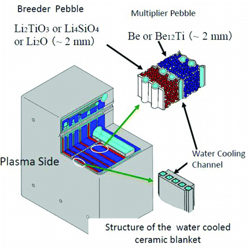
The key technologies of the tritium breeding blanket are dependent on the type of the blanket, as discussed in Section 4. In the case of water-cooled solid breeder type, the important R&D items are structural materials and the neutron breeder, the multiplier, and their integration into a module. An example of the design is shown in , where both breeder and multiplier compounds are made in a pebble form.
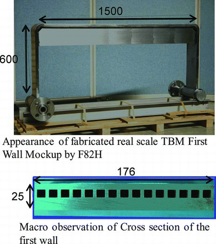
For use under high temperature of the fusion blanket, the reduced-activation martensitic ferritic steel, F82H (8Cr-2W-V-Ta), has been developed [Citation42]. Since then, material improvement and property data have been accumulated [Citation43, Citation44]. In fabrication technology development for the DEMO blanket, a hot isostatic pressing (HIP) bonding method [Citation45], especially for the first-wall structure, with built-in cooling tubes has been proposed, tested, and optimized (). On this base, a first-wall panel mock-up was fabricated and tested under a high heat flux of 2.7 MW/m2 up to 5000 cycles, showing a good fatigue performance certified by the International Energy Agency (IEA) Round Robin tests [Citation46].
5.2. TBM development
One of the missions of the ITER is to test nuclear components under the neutron environment. Among them, the most important is the tests of tritium breeding blankets, which are indispensable for DEMO. The development of tritium breeding blanket is in the program of each party, but its tests are done by utilizing the ITER as a neutron test bed. This program is called the “test blanket module (TBM)” program and may be implemented mostly after the achievement of the mission Q ∼ 10. Several different types of the blanket module are under development in the member countries.
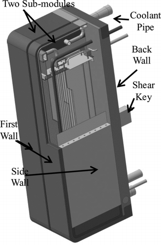
For example, in the case of the Japanese program, a configuration of the water-cooled ceramic breeder is shown in . The real-scale mock-up fabrication and tests are of great importance for qualification of the TBM prior to installation in the ITER. In this regard, a real-scale first-wall mockup was fabricated by the HIP method using candidate ferritic steel, F82H. The real-size side wall, back wall, and pebble bed box were also successively fabricated and tested under a simulated heat flux and cooling conditions equivalent to the ITER condition (0.5 MWm−2 × 80 cycles, cooled by 15 MPa, 300°C). These thermo-mechanical and hydraulic tests have proved the integrity of the TBM structure and fabrication technologies [Citation47]. Several first-wall irradiation tests for base materials and bonded structures demonstrated that the performance was well within an acceptable level [Citation48].
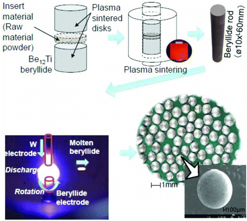
On the neutron multiplier and tritium breeding materials, the conventional designs employed laminated layers of the ceramic breeder pebbles (Li2TO3), beryllium (Be) pebbles, and water-cooling channels. Beryllium metal is the candidate neutron multiplier in Japanese and EU designs [Citation49–Citation51]. But to cope with an increasing volumetric swelling and steam-chemical reactivity of neutron-irradiated beryllium metal at high temperature, the fabrication technology for synthesis of Be12Ti intermetallic compound has been developed by the plasma sintering method from mixed elemental powders [Citation52] (). These products are expected to allow mixing of Li2TO3 and Be-Ti pebbles and remove barriers between the layers.
5.3. Structural materials development
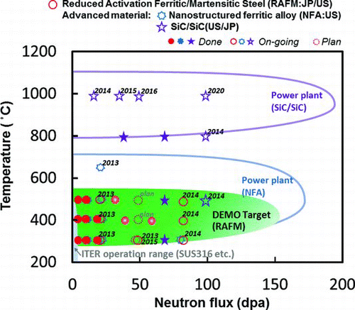
The basic functional tests of the tritium breeding blanket will be made in the ITER TBM program, but due to a lack of integrated neutron flux (<0.3 MWa/m2∼3 dpa), endurance tests of structural materials have to be made by much higher neutron flux facilities but with small-size samples. For this purpose, a long-lasting irradiation set-up by the fission materials reactor has been made, providing a highly valuable data. Small samples of the blanket structural materials have been irradiated under a high flux neutrons up to 68 dpa (). Assuming that a fusion power plant may be operated up to 150 dpa (this value corresponds to an operation of relatively a high neutron flux of about 5 MWm−2 peak and replacement in every 3–4 years), it is about half of the final target. The candidate structural material for most of the parties is the low-activation ferritic steel, but this metal can be used up to a temperature little more than 500°C. To increase power conversion efficiency from heat to electric power, higher operating temperatures of the blanket are preferred for future commercial reactors. From this view point, oxide dispersion strengthened (ODS) steel (up to 600°C) [Citation53] and SiC/SiC composites (800–1100°C) [Citation54] are thought to be candidate materials [Citation55, Citation56]. These materials are under development and their data will continue to be provided for application to the advanced blanket.
5.4. Facility for the materials test
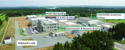
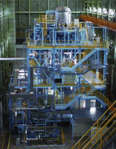
Although the irradiation by fission thermal neutrons provides valuable data for displacement of atoms in the metal, high-energy fusion neutrons of ∼14 MeV generates He atoms in the material due to nuclear reaction. How does the energy difference affect quantitatively on the material property, in particular at high fluence, is not clear yet. Therefore, a facility to simulate fusion neutron irradiation is necessary to confirm the endurance property of the candidate materials. Such a facility, named International Fusion Materials Irradiation Facility (IFMIF), using D-Li stripping reaction was planned () under the IEA, and its succeeding engineering design and prototype tests activities (IFMIF-EVEDA) were started as one of the joint projects named Broader Approach Activities by the EU and Japan. Neutrons to meet materials irradiation needs are generated by the simultaneous bombardment of two accelerated deuterium beams on to the liquid lithium flow. The small specimens mounted in the test cell at the back of the target will be exposed to a high neutron flux (typically 1018 nm–2s–1). Each deuterium beam (∼40 MeV, 125 mA each) will be obtained through a series acceleration by static, radiofrequency quadrupole (RFQ), and superconducting radiofrequency (SRF) Linac accelerations (). Under the Broader Approach Activities, components for a prototype accelerator from the ion source to the first unit of the SRF Linac have been developed and are now under fabrication. They will be transported, assembled, and tested in the IFMIF/EVEDA building at Rokkasyo site (). The liquid lithium loop test facility has been constructed at the Japan Atomic Energy Agency (JAEA) Oarai in Japan (), and the tests have been started to confirm a stable, free-boundary liquid lithium flow and to develop the lithium impurity control technology [Citation57].
Figure 31 Bird's eye view of the IFMIF (International Fusion Materials Irradiation Facility) as presented in the Comprehensive Design Report [Citation25]
![Figure 31 Bird's eye view of the IFMIF (International Fusion Materials Irradiation Facility) as presented in the Comprehensive Design Report [Citation25]](/cms/asset/db2762b6-b14b-4f04-a45b-89189f5eacd8/tnst_a_773166_o_f0031g.jpg)
5.5. Other technologies
Since R&Ds of other technology area are the extension of the technologies used in the ITER, and are dependent on the type of DEMO designs, they will be more clearly defined at a stage of developing DEMO project planning.
6. System issues and prospect toward DEMO reactors
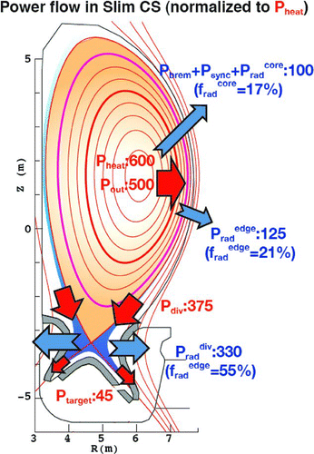
In the fusion reactor development, the plasma control characteristics and the component technologies have been and will be closely coupled until the DEMO stage. One fifth of the fusion reaction power given to the core plasma passes through the scrape-off layer (a region outside of the outermost magnetic boundary surface) either by thermal conduction or by radiation. As shown in , for example, if a fusion output of 3-GW machine is considered, the α-particle power is 600 MW, of which a power of about 100 MW is radiated and absorbed in the first wall, and the residual 500 MW crosses the scrape-off region [Citation58]. If this power directly flows into the divertor plate, the estimated heat flux to the divertor plate would be much higher than the technically acceptable level. To reduce significantly such heat loads to the divertor plate, the power dissipation by radiation due to interaction of the scrape-off plasma with neutral particles has been studied most extensively, where plasma in the scrape-off layer is thermally isolated (detached) from the divertor plate. In this approach, there are a lot of experimental trials such as injection of krypton or xenon into the scrape-off plasma, but a demonstration at high-energy density must wait until ITER experiments or a large-scale divertor simulation experiments are undertaken [Citation58].
One of the other approaches to relax the heat load to the divertor plate is to lower the plasma Q values while maintaining the overall energy production. Electricity generation may not be the only way to utilize fusion energy. Through the high-temperature heat from the fusion reactor by a machine comparable to the ITER (Q ∼ 10), H2 gas or a petroleum substitute can be produced from the biomass waste with a high power efficiency [Citation59].
In addition to the incorporation of the optimized operation scenario to control the burning plasma, the DEMO has to be operated with the minimum control actuators and diagnostics. This requirement stems from the different roles of the ITER and the DEMO. Namely, to keep the tritium breeding ratio greater than 1.05, the substantial space allowed for the ITER for heating and diagnostics systems has to be converted to the tritium breeding blanket of the DEMO. In addition, the control system of the DEMO as a power plant should be as simple as possible.
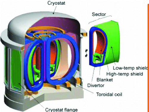
As a power plant leading to commercial reactors, a maintenance scenario of regular replacement of in-vessel components (blanket and divertor) has to be studied and developed extensively. Due to a huge mass of γ-radiative- and tritium-contaminated blanket modules, a system study of the maintenance scenario and the design of the handling tools and facility (hot cell) have to be made in the DEMO design. In the ITER device, the shielding blanket is composed of more than 400 small modules and is replaceable by a manipulator on a vehicle guided inside the vacuum vessel. However, the estimated replacement period for the same concept as the ITER seems to be too long, and other maintenance scenario should be considered in a fusion plant. One proposed candidate concept is a large module or a sector method where a blanket is divided into a minimum number of modules/sectors, and each module/sector is drawn out between adjacent TF coils () [Citation60]. Critical issues for this method might be the transport of a heavy weight (a few hundred tons) sector and where to set the tritium boundary in the maintenance period.
Figure 36 Sector blanket concept developed by the JAEA. Note: The EU has developed a concept to take out the module from the top of the tokamak
The plasma current can be driven either inductively or by an external current driver. An inductive current drive limits the operation time depending on the space for the CS coil. If a long operation is requested, the magnetic flux supplied by the CS coil must be large, and therefore, the machine size becomes larger. Such an inductively driven machine, for instance, a concept for day-time operation [Citation61, Citation62] or a concept of repetitious operation (for a few hours) combined with an external heat reservoir [Citation63] had been studied, but was regarded to be not competitive with a steady-state machine. However, under the change of possible public demands and the technical database, it may be worthwhile to make system reevaluation of the inductive concepts.
Assuming that R&D by ITER and other facilities would be successful and other issues discussed here are cleared, the electricity production by DEMO will be technically feasible within about 25–30 years, with a prospect for commercialization by the mid-twenty-first century.
7. Summary
Fusion energy research started almost 50 years ago. Roughly, an initial half of this period has been devoted to the physics exploration of plasmas and the latter half has been to the project exploration of both the physics and technologies. The technological aspect, in particular a nuclear machine, can be recognized from the experimental reactor phase materialized by the international joint project, ITER. The ITER program has been reviewed from its evolution in the 1980s. As a core program for fusion energy research, the ITER attracts the highest priority among the fusion programs in member countries. The construction of the ITER in now underway and is expected to start commissioning of the plasma in 2020. As foreseen from other similar international collaboration programs, building consensus takes more time than expected and the schedule, in principle, will be determined by the slowest decision. Nevertheless, the collaboration spirit makes it possible to find a way to avoid or mitigate the problems, as was seen in the ITER EDA phase, should a trouble take place in any party.
Actual demonstration of the electricity generation by fusion is a mission of the DEMO reactor. Although the DEMO program has not been formally established in any country, the preparatory works for DEMO on both plasma performance upgrade and technological issues have been continued and reviewed here. Discussions in Section 4 stems from the essence of one of the author's report [Citation60]. Long-lasting development and steady progress made so far predict the fusion final goal of electricity generation by the power plant to be achievable within 25–30 years, provided proper management for programming and funding is made.
Acknowledgements
The authors wish to thank Dr H. Takatsu, M. Akiba, T. Fujita, E. Tada, and H. Nakajima of the JAEA for helpful comments to prepare the review. They also thank for the supports by the ITER Organization and Domestic Agencies for providing photos.
Notes
Note: The construction started on the basis of the ITER-FEAT design.
IM: initial magnetization, EOB: end of burn.
References
- Keilhacker , M , Gibson , A , Gormezano , C and Rebut , P H . 2001 . The scientific success of JET. . Nucl Fusion , 41 : 1925
- 1998 . High performance reversed shear plasmas with a large radius transport barrier in JT-60 . Nucl Fusion , 38 : 207 – 221 .
- Kikuchi , M , Seki , Y , Oikawa , A , Kikuchi , M , Seki , Y , Oikawa , A , Ando , T , Ohara , Y , Nishio , S , Seki , M , Takizuka , T , Tani , K , Ozeki , T , Koizumi , K , Azumi , M , Kishimoto , H , Madarame , H , Ikeda , B , Suzuki , Y , Ueda , N , Kageyama , T , Yamada , M , Mizoguchi , T , Iida , F , Ozawa , Y , Mori , S , Yamazaki , S , Kobayashi , T , Hirata , S , Adachi , J , Shinya , K , Ozaki , A , Takase , H , Kobayashi , S , Asahara , M , Konishi , K and Yokogawa , N . 1991 . Conceptual design of the steady state tokamak reactor (SSTR) . Fusion Eng Design , 18 : 195
- Wesson , J . 2004 . Tokamaks , Oxford , , UK : 3rd ed. Oxford Science Publishing .
- 1999 . ITER physics basis . Nucl Fusion , 39 ( 12) : 2137 – 2664 .
- Shimada , M , Cambell , D J , Wakatani , M , Ninomiya , H , Ivanov , N and Mukhovatov , V . 2000 . “ Physics basis of ITER-FEAT ” . In Proceedings of the 18th IAEA Fusion Energy Conference ( , IAEA-CN-77 /ITERP/05 . 2000 Oct 4–10; Vienna (Austria): IAEA;
- Mori , S . 1987 . INTOR, introductory remarks . Plasma Phys and Cont Nucl Fusion Res. , 3 : 195
- 1989 . Vols. 1, 2 (ITER documentation series no. 3) , Vienna (Austria) : IAEA .
- 2001 . ITER engineering design activities successfully completed . ITER News Lett , 10 ( 7 ) : 9 – 11 .
- 1998 . Technical basis for the ITER final design report, cost review and safety analysis (ITER EDA documentation series no.16) , Vienna (Austria) : IAEA .
- 2002 . ITER technical basis (ITER EDA documentation series no. 24) , Vienna (Austria) : IAEA .
- Zohm , H . 1996 . Edge localized modes (ELMs) . Plasma Phys Cont Fusion , 38 : 105
- Shimada , M , Campbell , D J , Mukhovatov , V , Fujiwara , M , Kirneva , N , Lackner , K , Nagami , M , Pustovitov , V D , Uckan , N , Wesley , J , Asakura , N , Costley , A E , Donné , A JH , Doyle , E J , Fasoli , A , Gormezano , C , Gribov , Y , Gruber , O , Hender , T C , Houlberg , W , Kamada , Y , Leonard , A , Lipschultz , B , Loarte , A , Miyamoto , K , Mukhovatov , V , Osborne , T H , Polevoi , A and Sips , A CC . 2007 . Progress in the ITER physics basis, chapter 1: overview and summary . Nucl Fusion , 47 : S1 Ide S
- Dotle , E J , Houlberg , W A Kamada , Y . 2007 . ITER physics base . Nucl Fusion , 47 : S18
- Shimomura , Y . 2001 . ITER technology R&D . Fusion Eng Design , 55 : 97
- Tivey , R , Akiba , M , Driemeyer , D , Mazul , I , Merola , M and Ulrickson , M . 2001 . ITER R&D: vacuum vessel and in-vessel components: divertor cassette . Fusion Eng Design , 55 : 219 – 229 .
- Suzuki , S , Ezato , K , Seki , Y , Yokoyama , K , Hirose , T , Mori and , S and Enoeda , M . 2009 . Recent activities related to the development of the plasma facing components for the ITER and fusion DEMO plant . Physica Scripta , T138 : 014003
- Seki , Y , Ezato , K , Suzuki , S , Yokoyama , K , Enoeda , M and Mori , S . 2010 . Non-destructive examination with infrared thermography system for ITER divertor components . Fusion Eng Design , 85 : 1451 – 1454 .
- Jacquinot , J , Albajar , F , Beaumont , B , Becoulet , A , Bonicelli , T , Bora , D , Campbell , D , Chakraborty , A , Darbos , C , Decamps , H , Denisov , G , Goulding , R , Graceffa , J , Gassmann , T , Hemsworth , R , Henderson , M , Hoang , G T , Inoue , T. , Kobayashi , N , Lamalle , P U , Mukherjee , A , Nightingale , M , Rasmussen , D , Rao , S L , Saibene , G , Sakamoto , K , Sartori , R , Schunke , B , Sonato , P , Swain , D , Takahashi , K , Tanaka , M , Tanga , A and Watanabe , K . 2009 . Progress on the heating and current drive systems for ITER . Fusion Eng Design , 84 : 125 – 130 .
- Taniguchi , M , Dairaku , M. , Takemoto , J. , Tobari , H. , Tsuchida , K. , Yamanaka , H. , Watanabe , K. , Kojima , A. , Hanada , M. , Sakamoto , K. and Inoue , T. 2012 . Voltage holding study of 1 MeV accelerator for ITER neutral beam injector . Rev Sci Instrum. , 83 : 02B121
- Darbos , C , Henderson , M , Albajar , F , Bigelow , T , Bonicelli , T , Chavan , R , Denisov , G G , Fasel , D , Heidinger , R and Hogge , J P . 2009 . Progress in design and integration of the ITER electron cyclotron H&CD system . Fusion Eng Design , 84 : 651 – 655 .
- Matsuda , S . 2007 . The EU/JA broader approach activities . Fusion Eng Design , 82 : 435
- St. Paul-lez-Durance (France) , [23]http://www.iter.orgITER. Available form
- Press release. 10th ITER Council, Washington (DC); 21 June 2012
- IFMIF comprehensive design report , Available from: http//www.jea.org/dbtw-wpdtextbase/techno/technologies/fusion/IFMIF-CDR_PartA.pdf. Aomori (Japan)
- King , D . A report of the fusion fast track experts meeting http//www.fusion.org.uk/research.html[26]
- Maisonnier , D , Campbell , D , Cook , I , Di Pace , L , Giancarli , L , Hayward , J , Li Puma , A , Medrano , M , Norajitra , P , Roccella , M , Sardain , P , Tran , M Q and Ward , D . 2007 . Power plant conceptual studies in Europe . Nucl Fusion , 47 : 1524
- Kwon , M , Na , Y S , Han , J H , Cho , S , Lee , H , Yu , I K , Hong , B G , Kim , Y H , Park , S R and Seo , H T . 2008 . A strategic plan of Korea for developing fusion energy beyond ITER . Fusion Eng Design , 83 : 883
- Kolbasov , B N , Belyakov , V A , Bondarchuk , E N , Borisov , A A , Kirillov , I R , Leonov , V M , Shatalov , G E , Sokolov , Y A , Strebkov , Y S and Vasiliev , N N . 2008 . Russian concept for a DEMO-S demonstration fusion power reactor . Fusion Eng Design , 83 : 870
- Pan , C H , Wu , Y C , Feng , K M and Liu , S L . 2008 . DEMO development strategy based on China FPP program . Fusion Eng Design , 83 : 877
- Tanka , S and Takatsu , H . 2008 . Japanese perspective of fusion nuclear technology from ITER to DEMO . Fusion Eng Design , 83 : 865
- Strinivasan , R and Deshpande , S P . 2008 . Strategy for the Indian DEMO design . Fusion Eng Design , 83 : 889
- Pamera , J . 2009 . “ Efficiency and availability driven R&D issues for DEMO ” . In Proceedings of the 25th Symposium on Fusion Technology , Vol. 84 , 194 Fusion Eng Design .
- Ikuchi , M K , Seki , Y and Nakagawa , K . 2000 . The advanced SSTR . Fusion Eng Design , 48 : 265
- Nishio , S , Tobita , K , Ushigusa , K and Konishi , S . 2002 . Conceptual design of tokamak high power reactor (A-SSTR2) . J Plasma Fusion Res. , 78 : 1218
- Konishi , S , Nishio , S and Tobita , K . 2002 . DEMO plant design beyond ITER . Fusion Eng Design , 63-64 : 11
- Okano , K , Asaoka , Y , Yoshida , T , Furuya , M , Tomabechi , K , Ogawa , Y , Sekimura , N , Hiwatari , R , Yamamoto , T , Ishikawa , T , Fukai , Y , Hatayama , A , Inoue , N , Kohyama , A , Shinya , K , Murakami , Y , Senda , I , Yamazaki , S , Mori , S , Adachi , J and Takemoto , M . 2000 . Compact reversed shear tokamak reactor with a superheated steam cycle . Nucl Fusion , 40 : 635
- Najmabadiand , F . 2006 . The ARIES-AT advanced tokamak, advanced technology fusion power plant . Fusion Eng and Design , 80 : 3
- Maissonier , D , Cook , I , Sardain , P , Lorenzo , B , Edgar , B , Karin , B , Luigi , D P , Robin , F , Luciano , G , Stephan , H , Claudio , N , Prachai , N , Aldo , P , Neill , T and David , W . 2005 . The European power plant conceptual study . Fusion Eng Design , 75–79 : 1173
- Najmabadi , F . 1998 . Overview of ARIES-RS tokamak power plant . Fusion Eng Design , 41 : 365
- Nishio , S , Tobita , K , Konishi , S , Ando , T , Hiroki , S , Kuroda , T , Yamauchi , M , Azumi , M and Nagata , M . 2002 . “ Tight aspect ratio tokamak power reactor with superconducting TF coils ” . In Proceedings of the 19th Fusion Energy Conference (IAEA-CN-94, FT /P1-21)); Vienna (Austria): IAEA. Oct 14–19
- Tamura , M , Hayakawa , H , Yoshitake , A , Hishinuma , A and Kondo , T . 1988 . Phase stability of reduced activation ferritic steel: 8%Cr-2%W-0.2%V-0.04%Ta-Fe . J Nucl Mater. , 155–157 : 620
- Jitsukawa , S , Tamura , M , van der Schaaf , B , Klueh , R L , Alamo , A , Petersen , C , Schirra , M , Spaetig , P , Odette , G R , Tavassoli , A A , Shiba , K , Kohyama , A and Kimura , A . 2002 . Development of an extensive database of mechanical and physical properties for reduced-activation martensitic steel F82H . J Nucl Mater. , 307–311 : 179 – 186 .
- Shiba , K , Enoeda , M and Jitsukawal , S . 2004 . Reduced activation martensitic steels as a structural material for ITER test blanket. . J Nucl Mater. , 329–333 : 243 – 247 .
- Oda , M , Kurasawa , T , Kuroda , T , Hatano , T and Takatsu , H . “ Development of HIP bonding procedure and mechanical properties of HIP bonded joints for reduced activation ferritic steel F-82H ” . In JAERI-Tech 97-013) JAERI
- Hatano , T , Suzuki , S , Yokoyama , K , Kuroda , T and Enoeda , M . 2000 . High heat flux test of a HIP-bonded first wall panel of reduced activation ferritic steel F-82H . J Nucl Mater. , 283–287 : 685
- Hirose , T , Tanigawa , H , Yoshikawa , A , Seki , Y , Tsuru , D , Yokoyama , K , Ezato , K , Suzuki , S , Enoeda , M and Akiba . 2011 . Recent status of fabrication technology development of water cooled ceramic breeder test blanket module in Japan . Fusion Eng Design. , 86 ( 9–11 ) : 2265
- Tanigawa , H , Hirose , T , Shiba , K Kasada , R . Technical issues of reduced activation ferritic/martensitic steels for fabrication of ITER test blanket modules . Fusion Eng Design. , 2008;83:1471.
- Beeston , J M , Miller , L G , Wood , E L and Moir , R W . 1984 . Comparison of compression properties and swelling of beryllium irradiated at various temperature . J Nucl Mater. , 122-123 : 802 – 809 .
- Kawamura , H and Okamoto , M . 1998 . “ Proceedings of the 3rd IEA International Workshop on Beryllium Technology for Fusion (JAERI-Conf 98-001) ” . In Tokai (Japan): JAERI; 1997 Oct 22–24
- Giancarli , L , Chuyanov , V , Abdou , M and Akiba , M . 2007 . Test blanket modules in ITER: an overview on proposed designs and required DEMO-relevant materials . J Nucl Mater. , 367–370 : 1271 – 1280 .
- Enoeda , M , Tanigawa , H , Hirose , T , Suzuki , S , Ochiai , K , Konno , C , Kawamura , Y , Yamanishi , T , Hoshino , T , Nakamichi , M , Tanigawa , H , Ezato , K , Seki , Y , Yoshikawa , A , Tsuru , D and Akiba , M . “ Development of the water cooled ceramic breeder test blanket modeule in Japan ” . In Proceedings of the 10th International Symposium on Fusion Nuclear Technology (ISFNT 10); 2011 Sep 11–16, Portland (OR); Fusion Eng Design. 2012;87:1363–1369
- Kimura , A , Kasada , R , Kohyama , A , Tanigawa , H , Hirose , T , Shiba , K , Jitsukawa , S , Ohtsuka , S , Ukai , S , Sokolov , M A , Klueh , R L , Yamamoto , T and Odette , G R . 2007 . Recent progress in US-Japan collaborative research on ferritic steels R&D . J Nucl Mater. , 367–370 : 60 – 67 .
- Katoh , Y . 2004 . Perspectives of SiC-based ceramic composites and their applications to fusion reactors . J Plasma Fusion Res. , 80 ( 1 ) : 12
- Nishio , S , Ueda , S , Aoki , I , Kurihara , R and Kuroda , T . 1998 . Improved tokamak concept focusing on easy maintenance . Fusion Eng Design , 41 : 357
- Raffray , A R , El-Guebaly , L , Gordeev , S , Malang , S , Mogahed , E , Najmabadi , F , Sviatoslavsky , I , Sze , D K , Tillack , M S and Wang , X . 2001 . High performance blanket for ARIES-AT power plant . Fusion Eng Design , 58 : 59 – 549 .
- Garin , Pascal and Sugimoto , M . 2009 . Main baseline of IFMIF/EVEDA project2289 . Fusion Eng Design , 84 : 259 – 264 .
- Asakura , N Shimizu , K . 2010 . Simulation of power exhaust in edge and divertor of the SlimCS tokamak. . J Plasma Fusion Res Series , 9 : 136
- Konishi , S . 2005 . Potential fusion market for hydrogen production under environmental constraints . Fusion Sci Technol. , 47 : 1205
- Tobita , K , NIshio , S Enoeda , M . “ Conceptual design of the SlimCS fusion DEMO reactor ” . In (JAEA-Research 2010-019) JAEA
- Inoue , N Ogawa , Y . 1993 . Feasibility study on inductively operated day-long tokamak reactor . Nucl Fusion Suppl. (Plasma Physics and Controlled Nuclear Fusion Research 1992) , 3 : 347
- Najmabadi , F Conn , R W . “ The pulsed-tokamak fusion power plant – the Pulsar study – final report ” . San Diego, CA : UC San Diego . report no. UCSD-ENG-003)
- Horiike , H and Tokuda , T, . 1992 . Comparison between a steady-state fusion reactor and an inductively driven pulse reactor . JAERI-M , : 93 – 208 . Tokai (Japan): JAERI;

