Abstract
In order to promote a better understanding of failure mechanisms of high-burnup pressurized water reactor (PWR) fuels under reactivity-initiated accident (RIA) conditions, stress biaxiality in cladding has been estimated for the pellet-cladding (PC) mechanical interaction (PCMI) phase. The estimation was based on an analysis of the transient elongations of a pellet stack and a cladding tube measured in RIA-simulating experiments in the nuclear safety research reactor (NSRR) using the RANNS code. Stress biaxiality in the high-burnup PWR fuel cladding during the PCMI phase has been estimated to be 0.7–0.8, on average, at the mid-wall of the cladding. A comparison with fresh fuel test results and a sensitivity analysis showed that the effects of burnup and pulse width on cladding stress biaxiality are less than 10% for the investigated range. The present analysis also indicated that PC friction is strong, and that the cladding constraint on pellet stack elongation is significant irrespective of burnup. Therefore, it is recommended that strong PC friction be assumed, which is similar to the mechanical bonding condition, and that fuel pellets be treated as deformable materials in models of fuel behavior during the PCMI phase.
1. Introduction
Failure of high-burnup LWR fuels under reactivity-initiated accident (RIA) conditions is mainly induced by pellet-cladding (PC) mechanical interaction (PCMI) loading on embrittled cladding [Citation1,Citation2]. Because cladding deformation is substantially driven by the isotropic thermal expansion of fuel pellets, biaxial loadings on the cladding tube in the circumferential and axial directions are expected to occur during the PCMI phase. Previous studies reported that fracture strain in Zircaloy cladding decreases with increasing degree of stress biaxiality [Citation3–Citation5]. Therefore, cladding stress biaxiality under PCMI loading conditions is regarded as a key factor for defining a relevant failure limit for high-burnup fuels. Here, biaxiality is defined as the ratio of the axial component to the circumferential component of stress or strain in a cladding tube.
The cladding stress biaxiality under RIA conditions was estimated to range between 0.6 and 0.9 by a post-irradiation examination (PIE) after RIA-simulating experiments conducted in the CABRI reactor [Citation6]. However, the estimated biaxiality can be influenced by gas-induced cladding deformation after the PCMI phase since the estimation was based on the plastic or creep strains accumulated during the experiments. To avoid such an uncertainty, biaxiality must be estimated from online measurements of cladding axial deformation during RIA-simulating experiments.
Herein, stress/strain biaxialities in high-burnup pressurized water reactor (PWR) fuel cladding during the PCMI phase have been estimated on the basis of an analysis of transient elongations of the pellet stack and cladding tube measured in RIA-simulating experiments in the nuclear safety research reactor (NSRR) of the Japan Atomic Energy Agency (JAEA) using the RANNS code [Citation7]. Previously reported NSRR experiments with both fresh and high-burnup fuels were analyzed and compared to determine the effects of burnup on cladding stress biaxiality. The NSRR test conditions and the results of the elongation measurements are summarized in Section 2. The analysis procedures with the RANNS code are described in Section 3. In Section 4, the cladding stress/strain biaxialities under RIA conditions are estimated using the calculation conditions determined in Section 3, and the sensitivities of the biaxialities to some important parameters are discussed. Concluding remarks are provided in Section 5.
2. Summary of NSRR test conditions and results
This section summarizes the NSRR test conditions and the results of the elongation measurements that were analyzed in the present work. All the analyzed tests were previously reported, and the detailed descriptions of the tests are given in [Citation1,Citation2,Citation8–Citation11].
2.1. NSRR pulse irradiation test
For the fresh fuel tests, short test fuel rods were fabricated with unirradiated enriched UO2 pellets and cladding tubes. For the high-burnup fuel tests, fuel segments cut from high-burnup PWR fuel rods were refabricated into test fuel rods. The test rods had similar active lengths ranging from 110 to 136 mm.
The test fuel rods were equipped with two linear variable differential transducers (LVDTs) to measure transient elongations of the pellet stack and the cladding tube. The basic design of the test fuel rods and the arrangement of the LVDT elongation sensors are illustrated in . One LVDT detects the axial movement of the iron core placed between the pellet stack and the plenum spring, which directly shows pellet stack elongation by the thermal expansion of the fuel pellets. The other LVDT detects the axial movement of the iron core positioned at the top of the fuel rod, which shows cladding elongation.
Figure 1 Test fuel rod and instrumentation
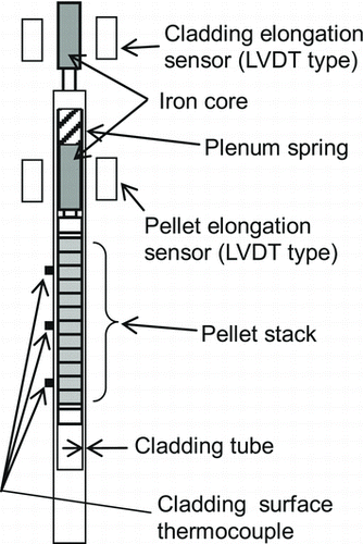
The cladding surface temperature was measured with Pt/Pt–13%Rh intrinsic thermocouples (TCs) of 0.2 mm diameter that were spot-welded near the mid-height of the pellet stack and at different axial positions.
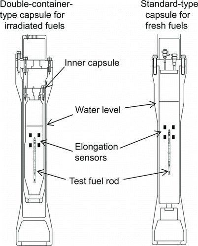
The instrumented test fuel rod was contained within a test capsule, as shown in , and the capsule was filled with coolant water. The sealed capsule was placed in the central test space of the NSRR, and the test fuel rod was subjected to pulse irradiation, which rapidly deposits energy in the fuel pellets. The NSRR can safely produce high power and short pulses to simulate a power excursion in a RIA [Citation8]. All the pulse irradiation tests analyzed in this study were conducted at room temperature and at atmospheric pressure, with stagnant coolant water.
Figure 2 NSRR test capsules
2.2. Test fuels
Twelve fresh fuel tests and 16 high-burnup fuel tests were conducted [Citation1,Citation2,Citation9–Citation11]. The pellet material is enriched UO2, and the cladding material is Zircaloy-4 for all the tests. Tests in which fuel failure occurred were not included in the present analysis because a failure event causes a strong disturbance on elongation measurements. identifies the analyzed test cases, and summarizes the peak fuel enthalpies during the pulse irradiation tests and the initial PC diameter gaps, which are essential inputs for RANNS calculations to analyze transient elongation behaviors. The peak fuel enthalpies of the TK tests are based on the isotopic compositions of U and Pu from recently conducted mass analysis, which is the most reliable method for evaluating peak fuel enthalpy in high-burnup fuel tests [Citation12]. For the remaining high-burnup fuel test cases, for which mass analysis data are not available, the isotopic compositions were determined using burnup calculation codes [Citation13].
Peak fuel enthalpies and initial pellet-cladding diameter gaps used as inputs for RANNS calculations
In terms of the initial PC gap conditions, these test fuels are categorized into four groups. The first group contains a fresh fuel with a very wide PC diameter gap (approximately 800 μm), referred to as “F-WG.” The second group contains a fresh fuel with a diameter gap of approximately 190 μm, referred to as “F-MG.” Both the F-WG and the F-MG group include only one test fuel, for which the test results were reported by Ishijima et al [Citation9]. The third group contains fresh fuels with a narrow diameter gap (approximately 40 μm), referred to as “F-NG.” The group F-NG includes 10 test fuels [Citation10]. The fourth group contains high-burnup fuels, referred to as “H-BN” [Citation1,Citation2,Citation11]. This group includes 16 test fuels of high-burnup PWR fuels with a rod average burnup ranging from 38 to 50 GWd/tU and of 14 × 14 and 17 × 17 assembly types. The PC gap of the H-BN test rods was estimated as being very small, as shown in Table . The procedure for estimating the PC gap of the H-BN test rods is explained in Section 3.
2.3. Test results
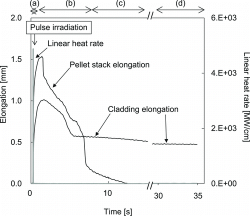
shows the measured elongation histories in the F-NG10 test, as an example of elongation histories under strong PCMI. All the other tests showed qualitatively similar elongation histories, except the F-WG case. The elongation histories show steep increases upon the prompt energy deposition induced by pulse irradiation. Pellet thermal expansion and PCMI likely dominate the elongation behaviors in period (a). The elongations show a rapid decrease in period (b), corresponding to thermal shrinkage due to heat removal from the pellets to the coolant water, through the cladding tube. The pellet stack elongation continues to rapidly decrease in period (c), whereas the decrease in cladding elongation is much smaller. Pellet cracking and yielding possibly occur during the PCMI phase owing to compressive force from the cladding tube. As a result, the axial displacement of the iron core attached to the pellet stack is sometimes negative after heat removal is completed, as shown in periods (c) and (d). Inversely, the cladding tube receives axial tensile stress from the pellet stack during the PCMI phase, and tends to have a residual elongation (i.e. axial plastic deformation as shown in period (d)).
Figure 3 Pellet stack and cladding elongations in the F-NG10 test
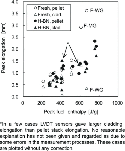
shows the peak values of pellet stack and cladding elongations for all the tests. The analysis and discussions below primarily focus on these peak elongation values because they are direct measures of axial deformations of the pellet stack and the cladding during the PCMI phase. The peak elongation values range from 0 to approximately 4 mm, and they clearly tend to increase with peak fuel enthalpy, reflecting the primary role of pellet thermal expansion in the elongation behavior. The significant deviation in the results of the F-WG and F-MG cases from those of the F-NG and H-BN cases is thought to reflect the effect of PCMI; pellet stack elongation is suppressed by the constraint force from the cladding tube in the narrow gap cases.
Figure 4 Peak elongations of pellet stack and cladding as functions of peak fuel enthalpy
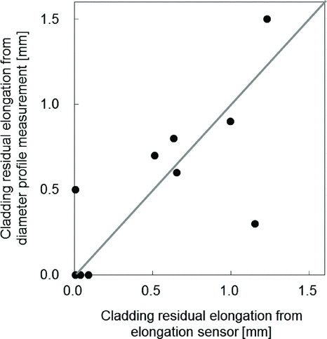
compares the cladding “residual elongation” values from the elongation sensors (i.e. the last values indicated from the LVDT sensor outputs) with those from the cladding outer-diameter profile data obtained in the PIEs. Although only some of the H-BN test results were available, the reasonable agreement between the LVDT sensor outputs and the PIE results confirms the reliability of the LVDT sensor outputs. The peak elongations shown in Figure are then considered to represent the actual deformation behaviors of the pellet stack and the cladding tube during the PCMI phase.
Figure 5 Comparison of cladding residual elongations between the elongation and the diameter profile measurements
3. RANNS calculation
3.1. System and geometry of RANNS calculation
The RANNS code analyzes thermal and mechanical behaviors of a single fuel rod under accident conditions. The basic framework and a major part of the modules are shared with the FEMAXI-7 code, the fuel behavior analysis code developed for normal operation conditions [Citation14]. A coupled calculation of one-dimensional thermal analysis in the radial direction and quasi two-dimensional finite-element method (FEM) mechanical analysis in the radial and axial directions is conducted at every time step. The pellet stack in one axial segment consists of 36 equal-volume ring elements. The cladding tube consists of eight equal-thickness ring elements, one inner oxide-layer element, and two outer oxide-layer elements. In each of the pellet stack and the cladding tube, all the element nodes are assumed to have identical axial displacement. The pellet stack and the cladding tube are mechanically connected by PC contact force in the radial direction and PC frictional force in the axial direction. Because the pellet stack has a uniform linear power distribution in the axial direction in the NSRR tests, the present analysis was conducted with only one axial segment. It is noted that the RANNS model geometry assumes a solid continuum cylindrical pellet stack even if actual pellets have cracks or are broken into some fragments.
3.2. Estimation of initial PC gap size in high-burnup fuels
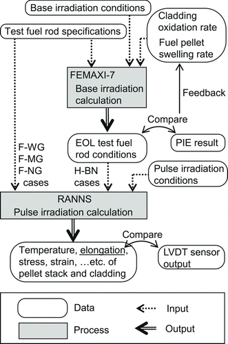
Since the H-BN test rods had been irradiated in commercial nuclear plants, the as-fabricated PC gap could not be directly adopted as the initial condition in the pulse irradiation tests. Hence, the PC gap of each H-BN test rod was estimated from the end-of-life (EOL) cladding diameter profile and the oxide thickness measured in the reference PIE, as described below.
Base irradiation calculations of the H-BN test rods were performed using the FEMAXI-7 code. The cladding oxidation rate was adjusted so that the calculated EOL oxide-layer thickness agreed with the PIE result. The fuel pellet swelling rate was also adjusted so that the calculated EOL cladding diameter agreed with the PIE result. The EOL PC gaps fed by the FEMAXI-7 calculations with the adjusted oxidation and swelling rate were employed as the initial condition in the RANNS calculation. illustrates the calculation procedure. According to the present estimation, the effective PC gaps were less than 10 μm, as shown in Table .
Figure 6 Calculation procedure
3.3. Calculation conditions used for estimating cladding stress/strain biaxiality
summarizes the material properties and models employed in the present analysis [Citation14–Citation21]. The measured cladding surface temperature history in each test was used as the boundary condition for the thermal analysis in the RANNS calculations to accurately consider cladding thermal expansion. The temperature history from the TC attached near the mid-elevation of the pellet stack was employed. The pellet relocation amount, PC frictional force in the fuel axial direction, and pellet yield stress level were adjusted to improve the overall agreement between the calculated and the measured elongations shown in Figure . Priority was given to the agreement of cladding elongations because it is considered to be a prerequisite factor for accurately estimating the cladding stress state, which is of interest here.
Summary of RANNS calculation conditions
Pellet relocation, which is interpreted as the apparent pellet expansion due to pellet cracking, was assumed to occur at the onset of power rise in the fresh fuel NSRR test. As the pellet temperature increases, the generated crack spaces are closed by pellet thermal expansion. In effect, the generated cracks reduce pellet stiffness to some extent until they are completely closed. This process is modeled by linearly changing Young's modulus as a function of the pellet relocation amount [Citation14]. A relocation of 1%, shown in Table , corresponds to an increase in the pellet outer diameter of 0.01 × D PO, where D PO is the pellet outer diameter.
The axial force induced by PCMI is treated with the “sliding state” model or the PC mechanical bonding model [Citation14]. The former model takes a friction coefficient approach in which frictional force is calculated as f=σπ(r 2 o − r 2 i ) F fric, where f is the frictional force in the axial direction of a fuel rod, σ is the PC contact pressure, r o is the cladding outer radius, r i is the cladding inner radius, and F fric is a scaling factor. The latter model assumes that the degree of axial deformation is shared between the pellet stack and the cladding tube.
Pellet plasticity is a predominant factor in the mechanical response of the pellet stack to the constraint force applied by the cladding tube. Tachibana et al.'s model gives temperature-dependent yield stress and tangential stiffness proportional to plastic strain [Citation20]. However, it is unreasonable to assume that pellets always obey such a model under RIA conditions because many cracks are observed in a pellet after pulse irradiation tests irrespective of fresh fuel tests or high-burnup fuel tests. In the present analysis, Tachibana et al.'s model was modified to better agree with the measurements. Specifically, the temperature dependency of the pellet yield stress was modified. Above 1273 K, the pellet yield stress was assumed to be constant and equal to the value at 1273 K. The effective pellet yield stress was then surveyed with a scaling factor F ys on the yield stress given by the modified Tachibana et al.'s model.
shows the calculation parameter sets ultimately used in the present analysis with regard to PC mechanical interaction in the axial direction and pellet plasticity. The parameter sets FR and HB2 are the best-fit cases for the fresh fuel test cases and the H-BN cases, respectively. The other cases are for the sensitivity study described in the next section. The parameter set RB corresponds to the PC mechanical bonding model with inhibited pellet yielding.
RANNS calculation conditions for sensitivity analysis
4. Results and discussion
4.1. Comparison between calculated and measured elongations
compares the measured elongations in the fresh fuel tests and the calculated elongations with the parameter set FR, for peak elongations of pellet stack, peak elongations of cladding, and residual elongations of cladding.
Figure 7 Comparison of elongations of fresh fuel rods between measurement and calculation with the parameter set FR
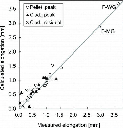
Solely the effect of pellet thermal expansion appears in the pellet stack elongation of the F-WG test rod because of the wide PC gap and the negligible constraint by the cladding tube. Hence, the agreement of pellet stack peak elongations in the F-WG case confirms that adopting the MATPRO pellet thermal expansion coefficient is adequate.
The agreement in the F-MG case (see Figure ) has been improved from the previous analysis conducted by Ishijima et al. owing to the treatment of pellet relocation and plasticity in the presence of constraint effect applied by the cladding tube. They analyzed the elongation behaviors with a fuel performance code that ignored the stress-induced deformation of the pellet stack and significantly overestimated pellet elongation [Citation9]. Also, in the present analysis, the calculation with the parameter set RB significantly overestimated pellet stack elongation.
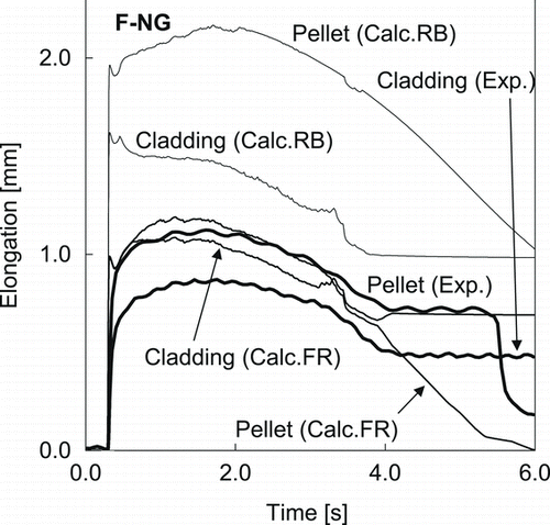
The constraint effect applied by the cladding tube is most obvious in the F-NG cases. shows the transient elongation histories for the F-NG2 test case. While the calculation with the FR set reasonably reproduces the measured elongation behaviors, the calculation with the RB set predicts elongations approximately two times as large as the measured value.
Figure 8 Comparison of elongation histories of the F-NG2 test rod between measurement and calculation with the parameter sets FR and RB
On the whole, Figure shows that the calculations with the parameter set FR are capable of reproducing the measured elongation behaviors of the fresh fuel rods. Accordingly, the cladding stress biaxiality in the fresh fuel tests, which will be described in Section 4.2, was estimated with the parameter set FR.
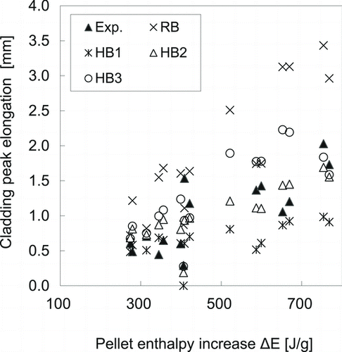
compares the elongations measured in the H-BN tests with those calculated with the parameter set HB2 in a manner similar to that of Figure . The agreement is obviously worse than that in the fresh fuel test cases shown in Figure . compares the cladding peak elongations measured in the H-BN tests with those calculated with the parameter sets HB1, HB2, HB3, and RB. It can be seen that the measured elongation plot (closed triangles) lies almost between the HB1 and the HB3 plot. It is expected that cladding stress biaxiality in the H-BN tests would lie between those calculated with the HB1 and those calculated with the HB3 parameter set. Accordingly, cladding stress biaxiality in the high-burnup fuel tests, which will be described in Section 4.2, was estimated with the parameter sets HB1 and HB3 in addition to the best-fit set HB2.
Figure 9 Comparison of elongations of high-burnup fuel rods between measurement and calculation with the parameter set HB2
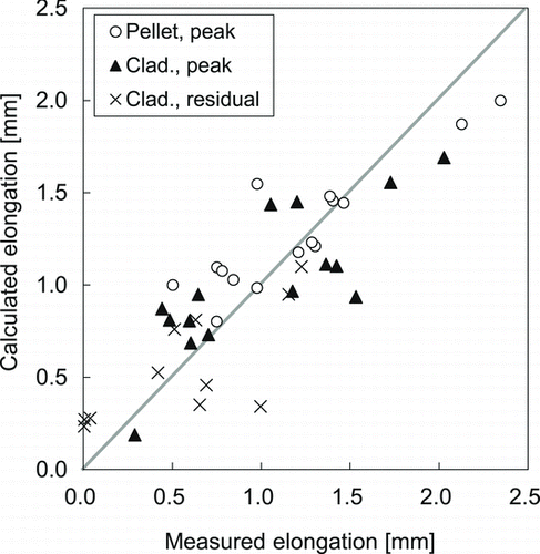
Figure 10 Comparison of cladding peak elongations of high-burnup fuel rods between measurement and calculation with the parameter sets HB1, HB2, HB3, and RB
4.2. Cladding stress / strain biaxialities
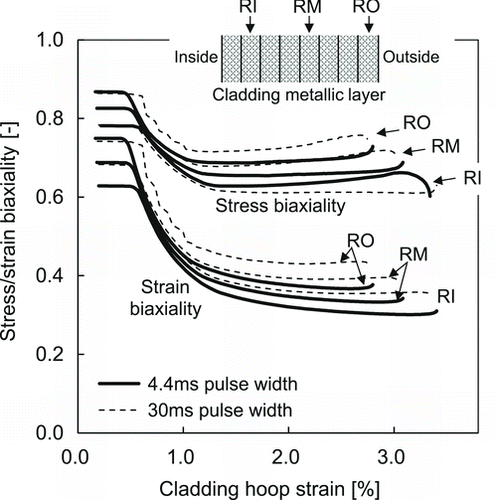
Two imaginary fresh fuel test cases were simulated to estimate cladding stress/strain biaxialities during the PCMI phase with the best-fit parameter set FR. A peak fuel enthalpy of 800 J/g was assumed. Pulse widths of 4.4 and 30 ms were assumed in the first and second imaginary cases, respectively, to check the effect of pulse width on the stress/strain biaxialities. The F-NG2 test case was referred to for the other test conditions such as the initial PC gap and the pellet stack length. shows the simulation results. The evolutions of the cladding stress/strain biaxialities are plotted as functions of cladding hoop strain. The stress biaxiality is slightly larger in the cladding outer region than in the inner region, which is attributed to the gradient of the cladding hoop strain in the radial direction. It can be seen that pellet yielding occurs at approximately 0.5% hoop strain as a result of PCMI, leading to a decrease in the stress/strain biaxialities. The effect of pulse width on the stress/strain biaxialities was found to be negligible.
Figure 11 Cladding stress/strain biaxialities as functions of cladding hoop strain at the positions RI, RM, and RO designated in the figure in an imaginary fresh fuel test case calculated with the parameter set FR and peak fuel enthalpy of 800 J/g
shows the results of the corresponding simulation for the high-burnup fuel tests, with a pulse width of 4.4 ms, a peak fuel enthalpy of 800 J/g, test conditions from the TK-6 case, and the parameter sets HB1, HB2, HB3, and RB. A tendency similar to the fresh fuel test cases is seen in the HB2 case; the stress/strain biaxialities decrease with an increase in the hoop strain after pellet yielding. Pellet yielding in the simulation with the HB2 set occurs at a hoop strain level higher than that in the simulation with the FR set shown in Figure . As a result, the stress/strain biaxialities calculated with the HB2 set maintain relatively large values up to higher hoop strain levels compared with those calculated with the FR set.
Figure 12 Cladding stress/strain biaxialities as functions of cladding hoop strain at the position RM designated in the figure in an imaginary high-burnup fuel test case calculated with peak fuel enthalpy of 800 J/g and the parameter sets HB1, HB2, HB3, and RB
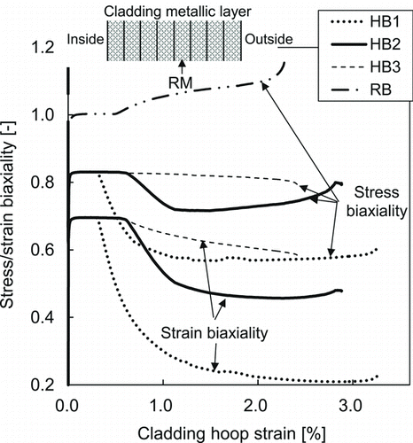
The stress biaxiality is approximately 0.7–0.8 according to the HB2 case shown in Figure . The stress biaxiality varies between 0.6 and 0.8 when one considers the calculations with the HB1 and HB3 parameter sets in addition to the HB2 set. This variation range corresponds to the uncertainty range of the stress biaxiality in the high-burnup fuel tests expected from the scatters shown in Figures and . The RB case clearly shows that assuming rigid behavior of the pellet stack leads to a significant overestimation of cladding stress biaxiality.
The estimated stress biaxiality 0.7–0.8 for the high burnup fuels is similar to that estimated in the CABRI tests [Citation6] despite the different test conditions between the NSRR and the CABRI such as coolant temperature, pulse width, and fuel stack length; the effect of these test conditions on cladding stress biaxiality seems not to be significant.
4.3. Mechanical behaviors of pellet stack and cladding
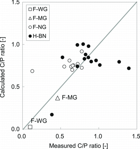
shows a comparison of the C/P ratio, the ratio of peak cladding elongation to peak pellet elongation, between the calculations and the measurements. The C/P ratio is an effective measure of the mechanical interaction between the pellet stack and the cladding tube in the axial direction. The F-WG and F-MG cases, with relatively wide PC gaps, gave low C/P ratios, as shown in the figure, because the pellet stack could have a certain amount of thermal expansion without constraint by the cladding tube before gap closure. It is noticeable that the F-NG cases gave C/P ratios similar to those in the H-BN cases, a clear indication that the PC sliding state after strong PCMI is, on average, similar between the fresh and the high-burnup fuels. The large F fric value of 6.0, at which PC sliding is limited, is hence considered to always be a good approximation with which PCMI under RIA conditions can be simulated, irrespective of the formation of a PC chemical bonding layer.
Figure 13 Comparison of measured and calculated C/P ratio
5. Conclusions
Stress biaxiality of high-burnup fuel claddings during the PCMI phase has been estimated to be, on average, 0.7–0.8 at the center of the cladding wall thickness. A comparison with the fresh fuel test results and a sensitivity analysis clarified that the effects of burnup and pulse width on cladding stress biaxiality are less than 10% for the investigated range. To accurately simulate fuel behavior during the PCMI phase, it is recommended that pellet deformation be treated as arising from constraint force applied by the cladding tube and that strong PC friction be assumed, which is effectively similar to the mechanical bonding condition.
Acknowledgements
The test fuels for the OI, MH, HBO, and TK experiments were provided by The Kansai Electric Power Co. Inc. The test fuels for the GK experiments were provided by Kyushu Electric Power Co. Inc. The information on fuel fabrication and irradiation was provided under cooperative research agreements between the Japan Atomic Energy Agency (JAEA) and Mitsubishi Heavy Industries Ltd., and between the JAEA and Nuclear Fuel Industries Ltd.
Related Research Data
References
- Fuketa , T , Mori , Y , Sasajima , H , Ishijima , K and Fujishiro , T. 1996 . “ Behavior of high burnup PWR fuel under a simulated RIA conditions in the NSRR ” . In Proceedings of CSNI Specialist Meeting on Transient Behavior of High Burnup Fuel 59 – 85 . Cadarache , , France Sep 12–14, Cadarache, France
- Fuketa , T , Sasajima , H and Sugiyama , T. 2001 . Behavior of high-burnup PWR fuels with low-tin Zircaloy-4 cladding under reactivity-initiated-accident conditions . Nucl Technol. , 133 : 50 – 62 .
- Yunchang , F and Koss , D A . 1985 . The influence of multiaxial stress states on the hydrogen embrittlement of zirconium alloy sheet . Metall Trans A. , 16A : 675 – 681 .
- Maki , H and Ooyama , M. 1975 . Plastic deformation and fracture behavior of Zircaloy-2 fuel cladding tubes under biaxial stress . J Nucl Sci Technol. , 12 : 423 – 435 . doi: 10.1080/18811248.1975.9733131
- Andersson , T and Wilson , A. “ Ductility of Zircaloy canning tubes in relation to stress ratio in biaxial testing ” . In Proceedings of Zirconium in the Nuclear Industry, 4th international symposium 60 – 71 . Stratford-upon-Avon , , England
- Cazalis , B , Desquines , J , Poussard , C , Petit , M , Monerie , Y , Bernaudat , C , Yvon , P and Averty , X. 2007 . The PROMETRA program: fuel cladding mechanical behavior under high strain rate . Nucl Technol , 157 : 215 – 229 .
- Suzuki , M , Saitou , H and Fuketa , T. 2006 . Analysis on pellet-clad mechanical interaction process of high burnup PWR fuel rods by RANNS code in reactivity-initiated accident conditions . Nucl Technol. , 155 : 282 – 292 .
- Muramatsu , Y and Udagawa , Y. 2009 . Instrumentation techniques in NSRR experiments , Vienna : International Atomic Energy Agency . IAEA-TECDOC-CD-1635
- Ishijima , K and Nakamura , T. 1996 . Transient elongation of a fresh fuel rod under reactivity initiated accident conditions . J Nucl Sci Technol. , 33 : 229 – 238 . doi: 10.1080/18811248.1996.9731894
- Sugiyama , T and Fuketa , T. 2004 . Effect of cladding surface pre-oxidation on rod coolability under reactivity initiated accident conditions . J Nucl Sci Technol. , 41 : 1083 – 1090 . doi: 10.1080/18811248.2004.9726333
- Sasajima , H , Sugiyama , T , Chuto , T , Nagase , F , Nakamura , T and Fuketa , T. 2010 . Identification of radial position of fission gas release in high-burnup fuel pellets under RIA conditions . J Nucl Sci Technol. , 47 : 202 – 210. . doi: 10.1080/18811248.2010.9711946
- Udagawa , Y , Suzuki , M , Sugiyama , T and Fuketa , T. 2009 . Stress intensity factor at the tip of cladding incipient crack in RIA-simulating experiments for high-burnup PWR fuels . J Nucl Sci Technol. , 46 : 1012 – 1021 . doi: 10.1080/18811248.2009.9711611
- Suyama , K , Junichi , K , Ookawa , U. and Ishikawa , M. 1999 . Libraries based on JENDL-3.2 for ORIGEN2 code: ORLIBJ32 , Ibaraki : JAERI . JAERI-data/code 99-003[in Japanese]
- Suzuki , M , Saitou , H and Udagawa , Y. 2010 . Light water reactor fuel analysis code FEMAXI-7; model and structure , Ibaraki : JAERI . JAEA-data/code 2010-035[in Japanese]
- Siefken , L J , Coryell , E W , Harvego , E A and Hohorst , J K . 2001 . SCDAP/RELAP5/MOD3.3 code manual: MATPRO—a library of material properties for light-water reactor accident analysis , Washington, DC : US Nuclear Regulatory Commission . NUREG/CR-6150
- Hagrman , D L and Reymann , G A . 1981 . MATPRO-VERSION 11: a handbook of materials properties for use in the analysis of light water reactor fuel rod behavior , Washington, DC : US Nuclear Regulatory Commission . NUREG/CR-0497
- Ohira , K and Itagaki , N. 1997 . “ Thermal conductivity measurements of high burnup UO2 pellet and a benchmark calculation of fuel center temperature ” . In Proceedings of the ANS Topical Meeting on Light Water Reactor Fuel Performance 541 – 549 . Portland , OR Mar 2–6
- MacDonald , P E and Thompson , L B . 1976 . MATPRO: version 09. A handbook of materials properties for use in the analysis of light water reactor fuel rod behavior , Washington, DC : US Nuclear Regulatory Commission . TREE-NUREG-1005
- Ross , A M and Stoute , R L . 1962 . Heat transfer coefficient between UO2 and Zircaloy-2 , Ontario (Canada) : Atomic Energy Commission of Canada Limited . CRFD-1075
- Tachibana , T , Furuya , H and Koizumi , M. 1976 . Dependence on strain rate and temperature shown by yield stress of uranium dioxide . J Nucl Sci Technol. , 13 : 497 – 502 . doi: 10.1080/18811248.1976.9734063
- Geelhood , K J , Luscher , W G , Beyer , C E and Cuta , J M . 2011 . FRAPTRAN 1.4: A computer code for the transient analysis of oxide fuel rods , Washington, DC : US Nuclear Regulatory Commission . NUREG/CR-7023.