Abstract
An efficient calculation scheme for the method of characteristics, which allows coarser ray separation width, is newly proposed. Effective lengths of characteristics lines are evaluated from the viewpoint of preservation of transmission probability in the present method. The effective lengths to preserve transmission probabilities can be rigorously estimated through detailed numerical integrations. However, calculation and storage of all effective lengths is inefficient since the transmission probabilities depend on many parameters such as azimuthal angle, polar angle, position of characteristics line, and total cross section. To resolve this issue, in this paper, the analytical equations for the effective lengths are derived from an assumption that distribution function of actual characteristics lengths can be expressed by a linear function. The new approach introduced in this paper is named as transmission probability preservation through linear approximation (TPPL). Verification results indicate that accurate results can be obtained by the TPPL even if ray separation width becomes coarse.
1. Introduction
In the method of characteristics (MOC) [Citation1], parameters for the ray tracing, which mean azimuthal angle division, polar angle division, and ray separation width, are important in the viewpoints of computational burden and accuracy. Although faster calculation can be performed with coarser ray tracing, accuracy would be degraded because of the spatial discretization error. In particular, for a heavy absorber cell such as high Pu content mixed oxide (MOX) fuel, very detailed ray tracing is required to obtain accurate result. In this paper, in order to improve the calculation efficiency, a calculation scheme to reduce discretization error due to the ray separation is discussed.
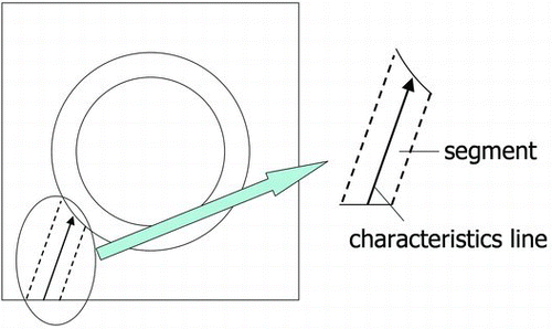
In MOC, characteristics lines are drawn in calculation geometry and the transport equation is solved along those lines. Each line represents the characteristics of a segment. An example of the characteristics line and the segment is illustrated in .
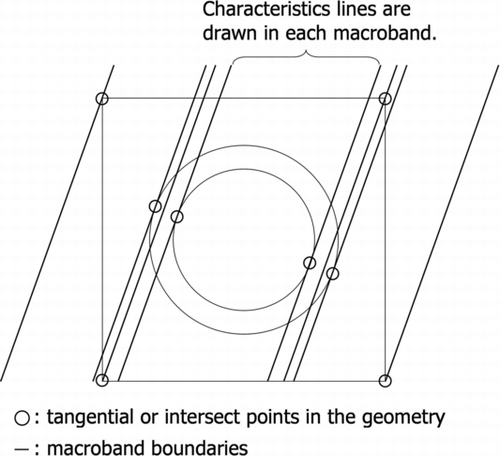
In the equidistant ray tracing method, a segment may contain geometrical discontinuous points, e.g. intersects of regions, hence large discretization error would be observed in such situation. To avoid this problem, the macroband method [Citation2] was developed and applied for MOC in the previous study [Citation3]. In the macroband method, a calculation domain is divided into “macrobands”, whose boundary lines are set on tangential and intersect points in the calculation geometry. Then the characteristics lines are drawn in the macrobands. The concept of the macroband ray tracing is shown in .
The discretization error due to the ray separation is expected to be reduced by the macroband method since segments contain no discontinuous points in the macroband method. Moreover, in the AEGIS code [Citation4], non-equidistant ray tracing method in each macroband based on the Gauss–Legendre quadrature set is adopted to reduce numerical-integration error. In this paper, reduction of the discretization error for ray tracing is discussed through another approach. The present paper focuses on preservation of the transmission probabilities in each segment. Févotte et al. proposed an improved treatment of the transmission probabilities using the Taylor expansion for MOC [Citation5]. On the other hand, in the present paper, the transmission probabilities are directly estimated without the Taylor expansion. The effective lengths to preserve the transmission probabilities are estimated on the basis of analytical integrations in this paper.
In Section 2, a calculation theory of the present paper is explained. Verification results are discussed in Section 3. Finally, the conclusion of the present paper is summarized in Section 4.
2. Calculation theory
For the first step of the present study, the following assumptions are considered in order to easily estimate the transmission probability.
| • | The macroband method considering material regions is used, i.e. macrobands are formed using tangential and intersect points of material regions. | ||||
| • | The ray separation widths are identical in each macroband, i.e. the equidistant ray separation in each macroband. | ||||
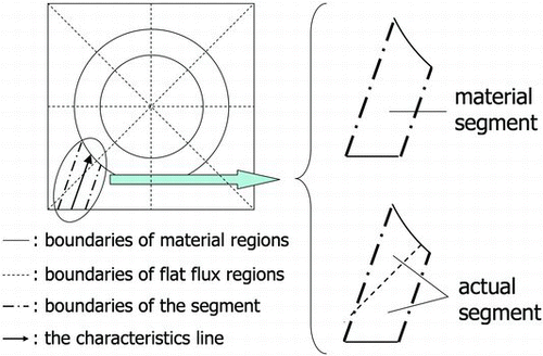
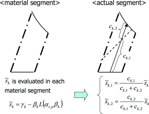
| • | The preservation of the transmission probability is considered in a “material segment”, which is defined as the segment without background meshes for flat flux regions (see ). | ||||
If the macroband is formed on the basis of flat flux regions, then the macroband widths become very narrow due to a large number of discontinuous points in many cases. Therefore, the macroband method based on material regions is assumed in this paper as a generally practical treatment of the macroband method. In such macroband method, actual segments may have discontinuous points as shown in the example of Figure . The analytical integration of transmission probability becomes complicated in such situation. To avoid this problem, the preservation of transmission probability is considered in the material region.
The equation for preservation of transmission probability in a segment is described as follows:
Σ t,i : total cross section of ith region (the index for the energy group is omitted), | |||||
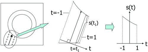
sk (t): length of line at coordinate t (see ) in kth material segment, | |||||
| |||||
sin θ
p
: sine of pth polar angle | |||||
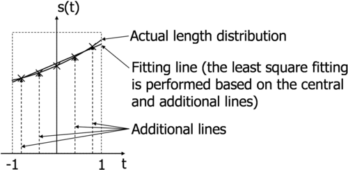
In Equation (Equation1), the coordinate system in a segment, which is normal to the direction of characteristics line, is normalized as −1 to 1. An example of the line length distribution, which means sk (t) in Equation (Equation1), is shown in Figure .
Equation (Equation1) indicates that the effective length depends on azimuthal angle, polar angle, position of line (index for parallel line), and total cross section. Therefore, the effective length cannot be determined only from ray tracing information, which is geometrically determined. As shown in Equation (Equation1), the effective length can be easily obtained when the integration of the left-hand side is evaluated. Although that integration can be numerically evaluated by using detailed ray tracing, such evaluation is not practical in some cases since calculation and storage of all effective length require additional heavy computational burden. To resolve this issue, distribution function of line length is assumed to be linear and the integration of the left-hand side is analytically evaluated. In two-dimensional MOC calculation for light water reactors (LWRs), most of the calculation geometries consist of lines and circles. Furthermore, in the macroband method, distributions of characteristics line length do not have any discontinuous points in segments. Therefore, the assumption on linear length distribution is appropriate when ray tracing widths are reasonably narrow. Assuming the linear approximation for line length distributions, sk (t) can be expressed as follows:
β k : slope of length distribution in kth segment, | |||||
γ k : intercept of length distribution in kth segment, i.e. sk (0). | |||||
By substituting Equation (Equation2), Equation (Equation1) can be rewritten as
From Equations (Equation3) and (Equation5), the equation for the effective length is derived as Equation (Equation6),
Now, let us define a special function, which is defined as Equation (Equation7),
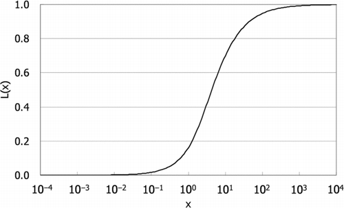
The shape of L(x) is plotted in . Using L(x), Equation (Equation6) can be rewritten as Equation (Equation8),
Although β k and γ k can be analytically estimated by using entering and exiting surface equations on chords, equations for β k and γ k would be complicated in some cases. Thus, in this paper, the least square fitting is used to estimate β k and γ k . To perform the fitting of a linear function, additional ray tracing lines in each segment are necessary since only the length at the central position in a segment is obtained through ordinary ray tracing scheme. Therefore, in addition to the original ray tracing, several lines are drawn in each segment to evaluate the slope and intercept of the length distribution. The example of the present fitting scheme is shown in .
In a pressurized water reactor (PWR) fuel assembly, the calculation geometry is composed of hundreds of cells. These cells can be classified into several cell types since most of the cells have the identical geometrical shapes. When ray tracing is performed in each cell type, computational cost for ray tracing can be reduced compared to that for whole assembly geometry. In such ray tracing method, the cost for the additional ray tracing of the present method is also small. Therefore, β k and γ k can be obtained without significant additional cost in such situation.
For the next discussion, let us consider a treatment of L(x) defined as Equation (Equation7). As shown in Equation (Equation8), multiplication of α i,p and β k is substituted into L(x) to estimate the effective length. When the sign of β k appeared in Equation (Equation8) becomes opposite, Equation (Equation9) is satisfied due to the asymmetric property of L(x) as an odd function (L(−x)=−L(x)),
Therefore, the sign of β k does not affect the form of Equation (Equation8). Since α i,p is always positive and only absolute value is considered for β k , L(x) should be evaluated only for positive x. Although L(x) has a complicated form as shown in Equation (Equation7), this function is easy to tabulate since it has smooth variation. Thus, the additional computation time can be almost eliminated by the tabulation before transport sweep.
The effective length of characteristics line can be estimated by Equation (Equation8), but it is for the material segment. In an actual MOC calculation, flat flux regions are used to define “actual” segments. Therefore, the effective lengths obtained by Equation (Equation8) should be converted to the actual segments used in the actual MOC calculation. In this paper, the effective length for the actual segment is normalized on the basis of the ratio of length at the central position of each segment,
| |||||
c k,h : length at the central position in hth segment of kth material segment. | |||||
An example of ![]() and c
k,h
is illustrated in .
and c
k,h
is illustrated in .
The differences of the calculation procedure from the conventional MOC are listed as follows.
| • | Tabulation of L(x) using Equation (Equation7) before transport sweep. | ||||
| • | Estimation of β k and γ k using the least squares method during the ray tracing. | ||||
| • | Correction of characteristics line length using Equation (Equation10) during transport sweep. | ||||
The present method is referred to as transmission probability preservation through linear approximation (TPPL). The improvement of the accuracy is confirmed through the verification calculations shown in the next section.
3. Verification
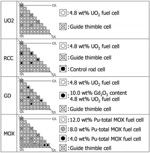
To confirm the accuracy of the TPPL, verification calculations are performed. In this verification, MOC calculations are performed on the basis of the conventional method and TPPL, and their accuracy is compared. All calculations in this verification are performed by the AEGIS code. As a conventional method, the Gauss–Legendre macroband method (GLM), which is currently adopted in the AEGIS code, is assumed. Although calculation results by the equidistant macroband method (EQM) are omitted in this paper, comparisons between the GLM and EQM can be shown in the previous study [Citation6]. The calculation geometries are listed below and illustrated in .
| • | 4.8 wt% UO2 fuel (“UO2”). | ||||
| • | 4.8 wt% UO2 fuel with control rods insertion (“RCC”). | ||||
| • | 10.0 wt% Gd bearing 4.8 wt% fuel (“GD”). | ||||
| • | 4.0, 8.0 and 12.0 wt% Pu-total MOX fuel (“ MOX”). | ||||
In this paper, above calculation geometries are called as UO2, RCC, GD, and MOX, respectively. The calculation conditions are listed in .
Table 1 Calculation conditions used in the verification calculations
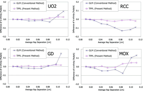
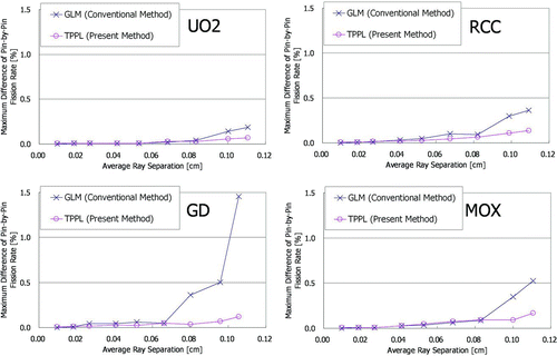
To evaluate the discretization error due to ray separation, detailed divisions for azimuthal and polar angles are used and only the ray separation width is varied. It should be noted that the actual ray separation widths are different from the input values, since widths of macrobands in calculation geometry are different in each calculation geometry. Therefore, input value means the maximum ray separation width. The input condition of ray separation widths (0.01–0.35 cm in input values) corresponds to approximately 0.01–0.12 cm in average ray separation widths. The calculation results are shown in and .
These figures show the trends of k-infinity differences and pin-by-pin fission rate differences with respect to the ray separation widths. The results in the GLM with 0.01 cm are used as the reference results. As described above, the actual ray separation widths are not identical with the input values. Therefore, the average ray separation widths are used as the horizontal axes in those figures. As shown in Figure , the differences of k-infinity become larger when the ray separation widths become coarser in the GLM. The maximum difference is larger than 0.1% Δk/k, and the trends of the differences have oscillation-like behaviors in some cases. On the contrary, in the TPPL, although the differences become slightly larger for coarser ray separation width, the maximum difference is smaller than 0.05% Δk/k. Furthermore, the oscillation-like behaviors in the TPPL are mitigated compared to those in the GLM. As shown in Figure , in the GLM, the differences of fission rate become larger when the ray separation widths become coarser similar to those of k-infinity. The maximum difference on pin-by-pin fission rate is approximately 1.5%. On the contrary, in the TPPL, the differences of fission rate are stably small even if the ray separation widths become coarser, and the maximum difference is smaller than 0.2%. From these results, the improvement of the accuracy by the TPPL is confirmed.
The additional computation time by the TPPL is approximately 5% of the total computation time. The additional memory is approximately 0.4% of the total memory storage at most in the present calculations. Therefore, the TPPL can be applied without significant impact on computational burden. As described above, the differences of k-infinity and fission rate distribution in the TPPL are smaller than 0.05% Δk/k and 0.2%, respectively, even with the coarsest ray separation width. On the other hand, in the GLM, average ray separation should be finer than approximately 0.05 cm to obtain the same accuracy. Computational time of the TPPL with the coarsest width is approximately 40% shorter than that of the GLM with 0.05 cm average width. Thus computational time can be significantly saved by the TPPL. However, it should be reminded that the advantage shown in the present verification calculations is partly attributed to the ray tracing method of the AEGIS code, which performs the ray tracing in each cell type. When the ray tracing is performed in each fuel assembly or whole geometry, estimation of β k and γ k may cause considerable increase of computation time in the TPPL.
4. Conclusions
In this paper, an efficient calculation scheme for MOC named TPPL is newly developed in order to reduce the discretization error due to ray separation. The present paper focuses on the preservation of transmission probability in each segment. The equation for the effective length of characteristics line to preserve the transmission probability can be analytically obtained by the assumption that distribution function of line length in each segment obeys a linear function. To evaluate the effective length, the slope and the intercept of the length distribution in each segment are required. These values can be estimated by the least square fitting with some additional characteristics lines during the ray tracing. When the ray tracing is performed in each cell type, the additional calculation cost of the TPPL is negligible small. In addition to the slope and the intercept, a special function, which consists of the logarithm and hyperbolic sine functions, is required to evaluate the effective length. Although the special function has a complicated form, the additional computation time can be almost eliminated by the tabulation before transport sweep.
The verification calculations are performed in four types of PWR fuel assembly geometries to compare the accuracy between the conventional method (GLM) and TPPL. In the GLM, the maximum difference of k-infinity is larger than 0.1% Δk/k and that of pin-by-pin fission rate is approximately 1.5%. On the other hand, in the TPPL, these differences are smaller than 0.05% Δk/k and 0.2%, respectively. From the verification results, the improvement of the accuracy by the TPPL is confirmed. The increases of computational time and memory are approximately 5% and 0.4% of total, respectively. It is confirmed that the TPPL can be applied without significant impact on computational burden when the ray tracing is performed in each cell type.
References
- Askew , J R . 1972 . A characteristics formulation to the neutron transport equation in complicated geometries , Winfrith : UKAEA . AEEW-M1108
- Villarino , E A , Stammler , R JJ , Ferri , A A and Casal , J J . 1992 . HELIOS: angularly dependent collision probabilities . Nucl Sci Eng , 112 : 16 – 31 .
- Ushio , T , Takeda , T and Mori , M . 2003 . Neutron anisotropic scattering effect in heterogeneous cell calculations of light water reactors . J Nucl Sci Technol , 40 : 464 – 480 . doi: 10.1080/18811248.2003.9715381
- Yamamoto , A , Endo , T , Tabuchi , M , Sugimura , N , Ushio , T , Mori , M , Tatsumi , M and Ohoka , Y . 2010 . AEGIS: an advanced lattice physics code for light water reactor analyses . Nucl Eng Technol , 42 : 500 – 519 . doi: 10.5516/NET.2010.42.5.500
- Févotte , F , Santandrea , S and Sanchez , R . 2007 . “ Improved transmission probabilities for the method of characteristics Proc. Int ” . In Topical Meeting on Mathematics & Computation and Supercomputing in Nuclear Applications Monterey , CA (M&C+SNA2007) Apr 15–19; Accompanied by: Video on CD-ROM
- Sugimura , N , Yamamoto , A , Ushio , T , Mori , M , Tabuchi , M and Endo , T . 2007 . Neutron transport models of AEGIS: an advanced next-generation neutronics design system . Nucl Sci Eng , 155 : 276 – 289 .
- Sartori , E . 1990 . Standard energy group structures of cross section libraries for reactor shielding, reactor cell and fusion neutronics applications: VITAMIN-J, ECCO-33, ECCO-2000 and XMAS, JEF/DOC-315, Revision 3, NEA Data Bank , Gif-sur-Yvette : Nuclear Energy Agency . Cedex
- Yamamoto , A , Tabuchi , M , Sugimura , N , Ushio , T and Mori , M . 2007 . Derivation of optimum polar angle quadrature set for the method of characteristics based on approximation error for the Bickley function . J Nucl Sci Technol , 44 : 129 – 136 . doi: 10.1080/18811248.2007.9711266
