Abstract
In ocean environment, the ship motion significantly affects the natural circulation behavior in ship-based integrated-type reactor. This paper theoretically and experimentally investigated natural circulation characteristics in symmetrical loops under rolling condition. Experiments were carried out on a test loop with a symmetrical configuration by simulating the structure of an accrual reactor. The theoretical results revealed that only angular acceleration contributes to the resultant force under zero power rolling condition. In a closed circuit with a uniform cross-section area, the angular acceleration force integral is proportional to the angular acceleration and the area enclosed by the circuit. The integral value varies over time and causes flow oscillations. However, the angular acceleration force does not influence the flow status in the shared part of the two symmetrical neighbor circuits due to force interactions. Rolling experiments with a zero power load confirmed these results. Full power experiments under rolling condition exhibited observable flow rate and temperature oscillations in each branch of the flow channel. The oscillations in the side flow channels had the same values for both the period and the phase with the variation of rolling angle. The angular acceleration force was the main cause of this. The oscillations in the middle channel had a period half the value of the rolling period. The periodical variation of the vertical component of gravity caused this. The horizontal component of gravity was out-phasing with angular acceleration. Therefore, it alleviated oscillation in the side channels. The experimental results showed that for the same rolling period, as the rolling angle increased, the average flow rate decreased and oscillation amplitudes increased. Also, as the power load increased, the oscillations in the middle channel increased and the oscillation in the side channel decreased.
1. Introduction
Natural circulation is being widely used in primary loop and residual heat removal system of advanced reactors because of its relative safety, facility simplicity, operational convenience, and cost reduction [Citation1, Citation2]. Some ship-based small-scale integrated type reactors have adopted natural circulation processes, such as the Japanese DRX (Deep Sea Research Reactor) [Citation3] and the Korean SMART (System-integrated Modular Advanced Reactor) [Citation4]. However, in ocean environments, ship motions, such as inclining, heaving, and rolling, significantly influence natural circulation. Rolling is a dynamical phenomenon that causes periodical variation in the driving force and also induces extra body forces such as the centrifugal force, the Coriolis force, and the force induced by angular acceleration. The amplitude and direction of these forces vary with time, location, rolling angle, rolling period, rolling center, and local velocity. The circulation flow rate and fluid temperature fluctuate continuously under the action of these body forces. Therefore, the flow and heat transfer process become very complex. An understanding of natural circulation characteristics under rolling condition is crucial for the design and operation of ship-mounted natural circulation systems.
Different groups have conducted experimental and numerical studies on specific systems in order to predict the influences of rolling motion. Pang et al. [Citation5] established the basic theoretical model of natural circulation in nuclear machinery under ocean environment. Gao et al. [Citation6] numerically analyzed the natural circulation characteristics of the separately arranged PWR primary loop in a nuclear-powered ship. The influences of rolling and pitching motion were compared. Murata et al. [Citation7, Citation8] experimentally investigated the heat transfer phenomenon in the core of a simulated marine reactor during rolling motion. Their test apparatus was equipped with the simulated core inner structures and the core bundle consisted of many heater rods. They found that rolling motion enhanced heat transfer in the core and they correlated heat transfer rate using the Richardson number. Based on the same apparatus, Murata et al. [Citation9] carried out experiments on the natural circulation characteristics during rolling motion, with the rolling angle range from 7.5° to 22.5°, and the period ranging from 5 s to 20 s. They found that as the rolling period became shorter, the amplitude of the flow rate oscillations became larger, and the phase lag between the rolling angle and loop flow rate oscillations also became larger. However, during their experiments the flow pattern of the primary coolant in the core was not observed. They estimated the outlines of the primary coolant flow by the temperature and assumed that the core flow rate did not oscillate. Tan et al. [Citation10, Citation11] experimentally studied single-phase natural circulation flow and heat transfer under rolling condition, with the rolling angle ranging from 10° to 20°, and the period ranging from 7.5 s to 12.5 s. They observed that rolling motion caused the natural circulation oscillation and decreased the average mass flow rate. However, their test section contained only one electrical heating tube and the complex flow pattern occurring in the actual reactor was not studied. Yan et al. [Citation12, Citation13] carried out an experimental and numerical study on the operational characteristics of a passive residual heat removal system under rolling motion. The effect of rolling motion upon heat transfer and the resistance coefficient was investigated using the experimental results. The effect of rolling motion upon gravity and additional pressure drop was also theoretically investigated. Generally, these authors all observed that rolling caused regular oscillation in flow and heat transfer in their specific systems. However, the description of the rolling effects requires more clarity and the oscillation mechanisms in different flow channels require more detailed study.
The objective of this paper is to provide insight into the behavior of the natural circulation and the mechanisms of the extra body forces induced by rolling motion. Experiments were carried out on a test loop that had a symmetrical configuration with multi-branch flow channels. This test loop simulated the complex flow patterns of an actual reactor. This paper carried out full-power experiments under rolling angle of 30° and 45° and obtained the oscillations of flow rate and temperatures in different flow channels. The oscillation mechanisms of different flow channels were investigated based on the characteristics of body forces and also on the test results for oscillation amplitude, period, and phase. Furthermore, the effects of rolling angle and power load were analyzed.
2. Test apparatus
The test apparatus consisted of test loops, rolling simulation platform, measurement systems, and power supply systems. The test loop contained a primary loop, secondary loop, and tertiary loop (). The primary loop contained the test section, which was fixed on the rolling simulation platform, while the secondary and the tertiary loop were located on land. The primary loop and secondary loop were connected by soft pipelines.
Figure 1 Test apparatus (a: test loops; b: EH model connection method; c: actual reactor arrangement)
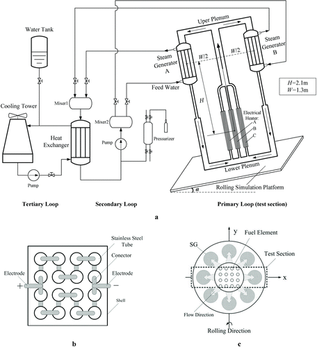
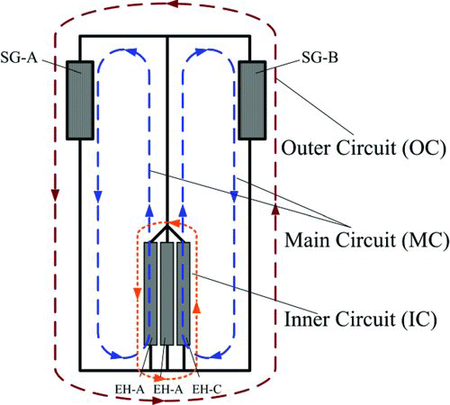
The test section consisted of three electrical heaters (EH), two steam generators (SG), and upper and lower plenums in a symmetrical arrangement. The coolant is demineralized water whose thermal hydraulic parameters are listed in . In the lower plenum water entered the EH, then flowed upward under the driving of bouncy force, and finally mixed in the rising pipe and upper plenum. After separation in the upper plenum, water entered the SG and then flowed back to the lower plenum after being cooled down. EH was made of 16 stainless steel heating tubes with the arrangement, as shown in Figure . EH were parallel connected and a DC was applied.
Table 1 Parameters of test section
The test section was able to simulate the complex flow channel of an actual reactor, although its configuration was still planar. First the test section contained multi-flow circuits including the main circuit (MC), inner circuit (IC), and outer circuit (OC) (). In an actual reactor, the fuel elements form minor flow channels similar to IC, and the SG forms minor flow channels similar to OC. Under the action of ship motion, fluid flows along these minor flow channels and forms complex flow patterns. Second, the primary loop retained the symmetry characteristics of an actual reactor that consists of multi-fuel elements surrounded by the SG (Figure ). This made it possible to investigate the different influences of rolling on the different branch flows.
The secondary and the tertiary loop were used to remove the heat generated by the EH. The secondary loop consisted of a pump, a heat exchanger, two mixers, and a pressurizer. The coolant for the secondary loop was water that driven by a pump rather than natural circulation. The mixers and control valves were used to set the coolant temperature and flow rates of the two circuits to equal values in order to avoid an unbalanced load. The secondary loop was kept at a pressure of 4.0 MPa and prevented the occurrence of two-phase flow in obtaining simplicity of equipment and operation. The pressurizer was filled with high-pressure nitrogen gas in order to adjust and maintain the pressure. The main equipment for the tertiary loop was the cooling tower, through which heat input from the secondary loop was finally emitted into the environment with the coolant circulation.
Ultrasonic flow meters measured the flow of natural circulation at the outlets of each EH module and SG. The meters were accurate to within 0.5% of the measured flow rate value and did not bring extra resistance to the circulation. Orifice-type flow meters measured the flow rates of the secondary and tertiary loops. Thermocouples with a measurement error of ± 1°C measured the temperature. A total of 36 thermocouples were installed at crucial positions throughout the entire test loop, including the inlets and outlets of the EH, SG, and the heat exchanger.
The rolling simulation platform rolled about two perpendicular axes, with period ranging from 13-21s and maximum rolling angle of 45°.
3. Results and discussion
3.1. Benchmark experiments
We carried out benchmark experiments under non-rolling and zero power conditions, respectively, in order to investigate the basic characteristics of natural circulation and rolling effects. The data obtained through these experiments will be used to contrast with the data obtained by full power experiments under large-scale rolling condition.
3.1.1. Non-rolling experiments
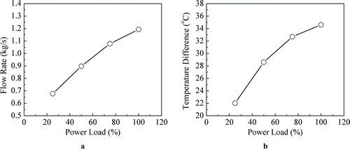
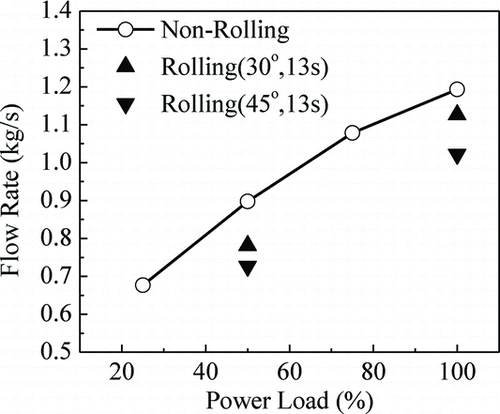
Non-rolling experiments were carried out under the power loads of 25%, 50%, 75%, and 100%, respectively. During experiments we recorded the flow rate and inlet/outlet temperatures of each flow channel, including the EH and SG. With the increase of power load, the flow rates and temperature difference between the inlet and outlet of the EH all increased, as shown in . Under full power load condition, the total flow rate (the sum of SG's flow rates or the sum of EH's flow rates) was 1.19 kg/s, being very close to the design value. Meanwhile, the flow rates and temperatures of branch flow channels kept symmetry, as shown in .
Table 2 Test results under no-rolling condition (100% load)
3.1.2. Zero power load experiments
In order to investigate the rolling effects on flow pattern under low power condition, zero power load experiments were carried out with maximum rolling angles of 30° and 45°, and a period of 13 s. Fluid was maintained at room temperature and atmospheric pressure. In this paper, the rolling angle varied with time as the function
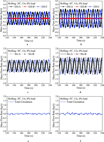
During experiments, the flow rates of EH-A, EH-B, SG-A, and SG-B (Figure ) fluctuated with large amplitudes (). The oscillation periods were all 13 s, the same as rolling period. Fluid only flows along the outer and inner circuit of the test section. The EH-A flow rate always equaled to the negative value of the EH-C flow rate, and the SG-A flow rate always equaled to the negative value – the SG-B flow rate. The total circulation flow rate and EH-B flow rate were always zero. The phase characteristics of oscillation indicate that rolling motion causes the opposite effect on the flows in the symmetrical channel pairs. For example, when rolling motion drives the fluid in SG-A to flow upward, it also drives the fluid in SG-B to flow downward. Asymmetrical flow patterns occurred. These results show that under no-power rolling condition fluid is driven by a periodical force; this force only imposes on side channels (such as SG-A, SG-B, EH-A and EH-C) and do not influence the fluid in the middle channels (such as EH-B).
Figure 4 Flow oscillations under zero power load rolling condition (a: flow rate of EH, 30° 13 s; b: flow rate of EH, 45° 13 s; c: flow rate of SG, 30° 13 s; d: flow rate of SG, 45° 13 s; e: total flow rate, 30° 13 s; f: total flow rate, 45° 13 s)
The mechanism of this phenomenon is analyzed below. For convenience, this paper analyzes the fluid flow mechanisms in the coordinate system attached to the test section (rolling system). In this system, gravity changes direction with the rolling angle variation and is therefore divided into horizontal (GH) and vertical (GV) component. Furthermore, this system is a non-inertial reference system and allows extra body forces, including the centrifugal force (CE), the Coriolis force (CO), and the force caused by angular acceleration (AA). As a result, the body force can be expressed by
Table 3 Body force component expressions and periods
Suppose a fluid with constant density is filled in an arbitrary planar loop L, which is closed, smooth, and has a uniform cross-section area. When L rolls about any axis perpendicular to the plane of L, the resultant force acting on the fluid is given by the integral of ![]() along L (anticlockwise direction is defined as positive)
along L (anticlockwise direction is defined as positive)
The resultant body force acting on the fluid in a closed loop is only related to the cross-section area, density, angular acceleration, and the area enclosed by the loop, despite the loop shape and rolling center position (Equation (Equation3)). The expression is quite simple even though the force field is complex. Only the force caused by angular acceleration contributes to the resultant force. The integrals of gravity and centrifugal force are both zero because of the constant density. Coriolis force is always perpendicular to the flow direction; hence it is not able to drive the flow, too.
The rolling-induced body force exists in all the circuit with positive enclosed area. In two neighbor circuits that have one shared channel, flow is controlled by the co-action of the forces in the individual circuit, which have the same value but in opposite direction, because of symmetry. The pressure difference imposed on the shared part of MCs is kept zero, despite the value and direction of the resultant force caused by rolling motion. This indicates that under zero power load condition, rolling motion does not influence the flow status in the middle channel. In the test section, flow oscillation caused by rolling motion only occurred in OC and IC, whereas the fluid in the middle channel is always at rest.
3.2. Full power rolling experiments
Natural circulation characteristics under rolling condition were experimentally investigated under the conditions shown in . In cases 1–4, the rolling periods were set as T = 13 s, which was the minimum period for the rolling platform. The period of T = 21 s was set for case 5 in order to investigate the influence of rolling period. At the beginning of each experiment, the natural circulation under non-rolling condition with full power input was initialized; then the rolling simulation platform was turned on and the flow rates and temperatures were recorded. Samples were recorded for each experiment ( ).
Table 4 Experiments under full power condition
3.2.1. Flow oscillations
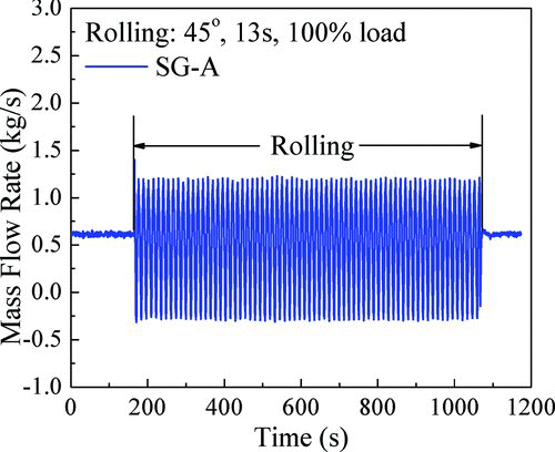
The flow rates through SG-A (left MC) and SG-B (right MC) both fluctuated with a period of T = 13 s (). The oscillations were intense. In case 4, even reverse flow occurred. The relative oscillation amplitude is defined as
Figure 6 Flow oscillations under 100% load rolling (a: rolling angle, case 2; b: rolling angle, case 4; c: rolling angle, case 5; d: mass flow rate of SG, case 2; e: mass flow rate of SG, case 4; f: mass flow rate of SG, case 5; g: mass flow rate of EH, case 2; h: mass flow rate of EH, case 4; i: mass flow rate of EH, case 5; j: total mass flow rate, case2; k: total mass flow rate, case 4; l: total mass flow rate, case 5.)
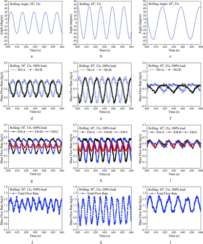
Flow through the EH fluctuated with different characteristics. The relative oscillation amplitude in EH-A and EH-C were about 60%, while that of EH-B was only 20%. The periods of EH-A and EH-C were both 13 s, whereas the period of EH-B was 6.5 s. The flow oscillation of EH-A and SG-A were out-phasing, whereas in zero power load rolling experiments they were in-phase. Total circulation flow fluctuated with a period of 6.5 s and was in-phase with the flow oscillation in EH-B.
Temperature and density differences occurred with power input and the integral values of GV, GH, and CE along a closed loop were no longer zero. Therefore, the comprehensive effect of these forces together with AA influenced the natural circulation process. GV is the driving force that forms natural circulation along MC. Its value varies with the period of T/2 (Table ). If GV act alone, a flow oscillation with a period of T/2 would arise, however, GV has same effect on the flow of symmetrical channel; therefore, the flow pattern remains symmetrical. GH always enhances the circulation in one MC and restrains it in the other MC, having the same effect as AA. GH also has the same period as AA. However, GH and AA have opposite phases. The effect of CE is not significant in this paper because the maximum centrifugal acceleration in the experiments was 0.4 m/s2 (α max = 45°, T = 13 s), which is far less than the acceleration of gravity.
For the side channels, such as EH-A, EH-C, SG-A, and SG-B, the variation of AA was the main cause of oscillation because only AA had the same period and phase as the oscillation. For example, when α = +α m (anticlockwise is positive), AA reached the maximum. Under the driving of AA, the flow in SG-A also reached a maximum (with a 2 s delay), and the flow in SG-B reaches a minimum. This was similar to the zero power load rolling experiments, despite the variation of flow rate curve shape. According to Equation (Equation3), the effect of AA was relative to the area enclosed by the loop and angular acceleration. The area enclosed by the IC was smaller then that enclosed by the OC, therefore the relative oscillation amplitudes of EH-A and EH-C were smaller than those of SG-A and SG-B.
For the middle channels, the flow oscillations were mainly caused by the variation of GV because oscillation and GV both had a period of T/2 and were in phase with each other. When the system reached the original position (α = 0°), GV reached a maximum and formed a crest in both EH-B and total circulation flow rate curves. This happened twice in one rolling period. Therefore, the flow oscillation period in the middle channel had the period of T/2.
3.2.2. Temperature oscillations
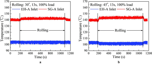
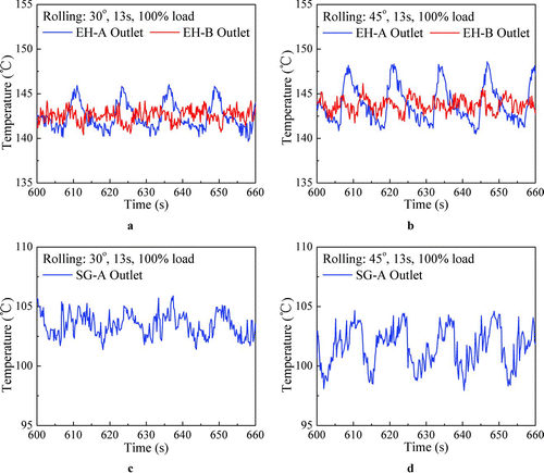
Rolling motion increased the inlet temperature of the SG and decreased the inlet temperature of the EH. The temperature difference between the hot leg and cold leg increased as a result (). Only EH-A and SG-A temperatures were presented, as the inlet temperatures of the EH and SG were uniform because of the full mixing in upper and down plenums. Regular oscillations of inlet temperature caused by rolling motion did not occur. Measurement noise caused the fluctuation because it had no regular period and its amplitude did not change after rolling began.
Observable temperature oscillations occurred at the outlet of the EH and SG (). In case 4, the maximum amplitudes of the temperature oscillations were at EH-A outlet (7°C). Temperature oscillations were mainly caused by the flow oscillations because the power load and parameters of secondary and tertiary loop were all fixed. Therefore, the amplitude, period, and phase characteristics of temperature oscillation were similar to those of flow oscillation.
3.2.3. Influence of rolling angle and rolling period
The intense of rolling motion effects on the natural circulation is mainly relevant to the rolling angle αmax and rolling period T. In considering the branch flow oscillation, we substituted Equation (Equation1) into Equation (Equation3) and provide the resultant force caused by angular acceleration (AA) acting on the fluid in an arbitrary loop:
From Equation (Equation5) we can see that the magnitude of AA that causes the branch flow oscillation is proportional to αmax and T −2. This means that both to increase the rolling angle and shorten the rolling period will introduce larger amplitude of oscillation in the flow rates of branch channels, as shown in Figures . Also we can see that the AA is proportional to the inverse square of rolling period that makes the rolling period more sensitive to the value of AA than rolling angle. For example, in case 5 the rolling angle increased 1.5 times and rolling period decreased 1.6 times in comparison to case 2; however, under such conditions, the branch flow oscillation amplitude of case 2 was much larger than that of case 5 (Figure ).
Meanwhile, in case 5, the periods of flow oscillations in electrical heater A and C were both half the rolling period and the flow oscillations in the three electrical heaters were almost in phase, which was very different with the result of case 2 and case 4 (Figure (g–i)). The reason may be that with the increase of rolling period the influence of AA decreased rapidly (Equation 5) and then the flow oscillations in the electrical heaters was mainly controlled by the vertical component of gravity (GV) whose period was half the rolling period.
Total circulation flow rate decreased with the increase of αmax (). This is because the total circulation was driven by GV, whose integral value along the main circuit (MC) is
where H is the altitude difference between the centers of the EH and SG, Δρ is the density difference between cold leg and cold leg. Equation (Equation6) indicates that an increase of αmax decreases the influence of GV and therefore depresses the total circulation.
3.2.4. Influence of power load
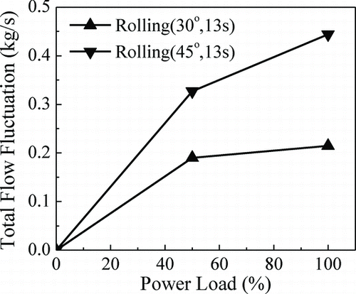
The amplitude of total flow oscillation increased with the increase of the power load (). Meanwhile, the increase rate of flow oscillation amplitude decreases with the increase of power load. This is because a power load increase introduces the increase of Δρ and, according to Equation (Equation6), the oscillation amplitude of ΔpV (driven force of total circulation) increases. This matched the results of Murata [Citation7] and Yan [Citation12].
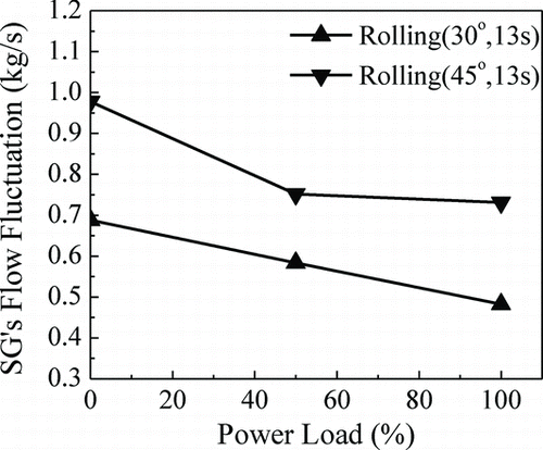
However, this paper found that the oscillation amplitude of the side flow channels decreased with the increase of the power load (). Previous studies have not reported this. The branch flow oscillations were mainly caused by the variation of AA and influenced by GH. AA and GH were out-phasing; hence, they had opposite influences on the circulation. As AA was dominant, GH had the effect of alleviating the oscillation. The integral of GH along the MC is
where W is the width of MC. The density difference Δρ increased as the power load increased, then ΔpH also increased, according to Equation (Equation7). As a result, the branch flow oscillation was further restrained.
4. Conclusions
This paper experimentally investigated natural circulation characteristics in a symmetrical loop under rolling conditions. The conclusions were as follows:
| 1. | The test section had a symmetrical configuration and contained multiple flow channels, including the main circuit, outer circuit, and inner circuit (Figure ). Based on this test section, the complex flow patterns of an actual reactor were studied. For the experiments conducted in this research, the maximum rolling angle was 45°, and the minimum rolling period was 13 s. | ||||
| 2. | Rolling motion introduced periodical resultant force along an arbitrary closed loop under the small power load and negligible density variation conditions. Despite the complexity of the body forces acting on the fluid, only the force caused by angular acceleration contributed to the resultant force, which was proportional to the area enclosed by the loop and the angular acceleration. This result indicates that minimizing the area enclosed by the loop is helpful in restraining the influence of rolling motion. | ||||
| 3. | Two benchmark experiments were carried out. The non-rolling full power experiments verified the design of the test section. The zero power load rolling experiments validated the analysis results. In the later experiments, large flow oscillations occurred in the side channels, but the fluid in middle channel always stayed at rest. This indicates that the force caused by angular acceleration does not influence the flow in the middle channel. | ||||
| 4. | Flow oscillations occurred in every flow channel for the full power rolling experiments. Similar to the zero power load rolling experiments, the variation of the force caused by angular acceleration also dominated oscillation in the side flow channels under full power rolling conditions. The side channels flow oscillation and the force caused by angular acceleration both had a period of T (rolling period). The variation of vertical component of gravity dominated oscillation in the middle channel, which had a period of T/2. The flow oscillations induced temperature oscillations at the outlets of electrical heater and steam generator, which had similar period and phase characteristics to those of the flow oscillations. In case 4 (α max = 45°, T = 13 s), the maximum relative oscillation amplitude of the flow through steam generator was 158% (reverse flow occurred) and that through electrical heater was 60%. The maximum temperature oscillation was 7°C. | ||||
| 5. | The influences of rolling angle, rolling period, and power load were analyzed. As the rolling angle increased or rolling period decreased, the flow oscillation amplitudes increased. The total circulation flow rate decreased with the increase of rolling angle. As power load increased, the density difference between cold leg and hot leg increased and enhanced the influence of gravity. This caused the flow oscillation in the middle channel increased and that in side channel decreased, for the former was induced by the variation of the vertical component of gravity, while the latter was alleviated by the horizontal component of gravity. | ||||
Nomenclature
| A | = |
area enclosed by a loop [m2] |
| AA | = |
body force induced by angular acceleration [N/m3] |
| CE | = |
centrifugal force [N/m3] |
| CO | = |
Coriolis force [N/m3] |
| EH | = |
electrical heater |
| f | = |
volumetric body force [N/m3] |
| g | = |
gravity acceleration [m/s2] |
| GH | = |
horizontal component of gravity [N/m3] |
| GV | = |
vertical component of gravity [N/m3] |
| H | = |
altitude difference between the centers of SG and EH [m] |
| IC | = |
inner circuit |
| MC | = |
main circuit |
| OC | = |
outer circuit |
| p | = |
pressure [Pa] |
|
| = |
position vector [m] |
| S | = |
cross-section area of a closed loop [m2] |
| SG | = |
steam generator |
| t | = |
time [s] |
| T | = |
rolling period [s] |
|
| = |
velocity [m/s] |
| W | = |
loop width [m] |
| Greek letters | = | |
| α | = |
rolling angle [rad] |
| αmax | = |
maximum rolling angle [rad] |
| α′ | = |
angular velocity [rad/s] |
| α′′ | = |
angular acceleration [rad/s2] |
| ρ | = |
density [kg/m3] |
Acknowledgements
The authors gratefully acknowledge supports for this work from Project 11072131 of The National Natural Science Foundation of China and Project 2010Z02275 of Tsinghua University, Beijing, China.
References
- IAEA . 2005 . Natural circulation in water cooled nuclear power plants, IAEA-TECDOC-1474 , Austria : International Atomic Energy Agency .
- IAEA . 2009 . Passive safety systems and natural circulation in water cooled nuclear power plants, IAEA-TECDOC-1624 , Austria : International Atomic Energy Agency .
- Ishida , T and Yoritsune , T . 2002 . Effects of ship motions on natural circulation of deep sea research reactor DRX . Nucl Eng Des , 215 : 51 – 67 . doi: 10.1016/S0029-5493(02)00041-9
- Kim , J H , Kim , T W , Lee , S M and Park , G C . 2001 . Study on the natural circulation characteristics of the integral type reactor for vertical and inclined conditions . Nucl Eng Des , 207 : 21 – 31 . doi: 10.1016/S0029-5493(00)00417-9
- Pang , F G , Gao , P Z and Wang , Z X . 1995 . Theoretical research for effect of ocean conditions on natural circulation . Nucl Power Eng , 16 : 330 – 335 .
- Gao , P Z , Liu , S L and Wang , Z X . 1999 . Effects of pitching and rolling upon natural circulation . Nucl Power Eng , 20 : 228 – 231 .
- Murata , H , Sawada , K and Kobayashi , M . 1990 . Natural circulation characteristics of a marine reactor in rolling motion . Nucl Eng Des , 118 : 141 – 154 . doi: 10.1016/0029-5493(90)90053-Z
- Murata , H , Sawada , K and Kobayashi , M . 2000 . Experimental investigation of natural convection in a core of a marine reactor in rolling motion . J Nucl Sci Technol , 37 : 509 – 517 . doi: 10.1080/18811248.2000.9714924
- Murata , H , Sawada , K and Kobayashi , M . 2002 . Natural circulation characteristics of a marine reactor in rolling motion and heat transfer in the core . Nucl Eng Des , 215 : 69 – 85 . doi: 10.1016/S0029-5493(02)00042-0
- Tan , S C , Su , G H and Gao , P Z . 2009 . Experimental and theoretical study on single-phase natural circulation flow and heat transfer under rolling motion condition . Appl Therm Eng , 29 : 3160 – 3168 . doi: 10.1016/j.applthermaleng.2009.04.019
- Tan , S C , Gao , P Z and Su , G . 2008 . “ Characteristic of natural circulation tTemperature oscillation under rolling motion condition ” . In Proc. ICONE 16 May 11–15
- Yan , B H , Yu , L and Li , Y Q . 2009 . Research on operational characteristics of passive residual heat removal system under rolling motion . Nucl Eng Des , 239 : 2302 – 2310 . doi: 10.1016/j.nucengdes.2009.06.026
- Yan , B H and Yu , L . 2012 . The experimental and theoretical analysis of a natural circulation system in rolling motion . Prog Nucl Energy , 54 : 123 – 131 . doi: 10.1016/j.pnucene.2011.07.005
