Abstract
In this study, a technique has been developed for diagnosing in on-line the state of the steam generator of the fast-breeder reactor (FBR) “Monju” by estimating an unobserved important state variable from observed data. The secondary coolant of liquid sodium faces to water/steam across a thin metal tube wall in the steam generator. Therefore, it is very important to detect a small anomaly of the wall of heat transfer tubes at an early stage. The aim of this study is to develop a technique for diagnosing in on-line a state of the steam generator by estimating an overall heat transfer coefficient, which is an unobserved important state variable, from observed data. This study shows simplified mathematical models of superheater and evaporator to estimate the overall heat transfer coefficient. The applicability of the technique is confirmed by configuring state observer with the mathematical model and noise filter and estimating using simulated data. As the results of the estimations, relative errors of the overall heat transfer coefficient of the superheater and the evaporator are less than ±0.5%.
1. Introduction
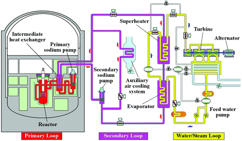
The fast-breeder reactor (FBR) uses liquid sodium as a coolant. It is necessary to handle liquid sodium with caution due to its chemical characteristics. The steam generator, which consists of an evaporator and a superheater, generates steam by the heat of sodium coolant. As shown in , the secondary coolant of liquid sodium from an intermediate heat exchanger flows from the superheater to the evaporator. On the other hand, the water/steam flows from the evaporator to the superheater. The secondary coolant of liquid sodium faces to water/steam across a thin metal tube wall in the steam generator. The sodium–water reaction may happen by a pinhole or crack occurring at the wall of a heat transfer tube. Therefore, it is very important to detect any anomaly of the wall of heat transfer tubes at an early stage.
The traditional inspection techniques for the wall of heat transfer tubes, such as eddy current testing (ECT), can only carry out in a maintenance period and require a great investment of time and a wide range of processes such as cool-down process, coolant drain, inspection preparations, inspection, elevated temperature process and coolant filling. In addition, the sudden anomaly cannot be detected during operation by the traditional inspection techniques [Citation1–Citation4]. Meanwhile, there is a hydrogen meter as one of the traditional techniques detecting anomalies during operation. The hydrogen meter detects the anomalies such as the pinhole and crack by detecting hydrogen gas by the sodium–water reaction. However, the hydrogen meter cannot prevent the sodium–water reaction from occurring.
The aim of this study is to develop a technique for diagnosing in on-line the state of the steam generator by estimating the overall heat transfer coefficient, which is an unobserved important state variable, from observed data such as temperature, pressure and flow rate. This technique can diagnose the steam generator during operation and does not require much time and processes. By occurring erosion-corrosion wastage at the wall of a heat transfer tube, the overall heat transfer coefficient increases due to the decrease in thermal resistance. So, it becomes possible to detect an indication of anomaly of the wall of the heat transfer tube such as a pinhole or crack at an early stage with estimating and monitoring the overall heat transfer coefficient. Thus, the developed technique can prevent the sodium–water reaction from occurring. On the other hand, the overall heat transfer coefficient decreases due to the increase in thermal resistance by adherence of water stain or scale to the wall of the heat transfer tube. So, it becomes possible to grasp a decline of heat transfer efficiency with estimating and monitoring the overall heat transfer coefficient. Therefore, maintenance using the developed technique together becomes safer and more efficient than only time-based maintenance.
This study describes in detail simplified mathematical models of superheater and evaporator to estimate the overall heat transfer coefficient and shows the applicability of the technique confirmed by the estimation using simulated data.
2. Simplified models
2.1. Superheater
The superheater of Japanese prototype FBR “Monju” consists of a cylindrical vessel with a helical heat transfer tube bundle inside. The number of helical heat transfer tubes is 147. The liquid sodium flows through the vessel outside the helical heat transfer tubes and the steam flows inside the helical heat transfer tubes [Citation5,Citation6]. Thus, the superheater has a complicated structure.
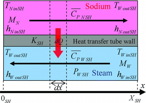
The number of sensors to observe the process values is limited by the complicated structure. The observed process values of the two coolants flowing inside the superheater are temperature, pressure and mass flow rate at the inlet and outlet of the superheater. Then, the structure of the superheater is expressed in a simplified model of countercurrent type as shown in for developing a simplified mathematical model to estimate the overall heat transfer coefficient. As shown in Figure , mass flow rate M, temperature T, pressure P, averaged specific heat under constant pressure ![]() and specific enthalpy h are used for deriving a simplified mathematical model. Provided, however, that the steam inside the superheater is constant in pressure because the pressure loss is negligibly small, heat exchange of the vessel and the air around the superheater is excepted from consideration and all the steam flowing into the superheater is superheated steam. The averaged specific heat under constant pressure and specific enthalpy are calculated from mass flow rate, temperature and pressure at the inlet and outlet of the superheater. Therefore, the overall heat transfer coefficient can be estimated from few observed data with the simplified mathematical model. The simplified mathematical model is applicable to heat exchangers of various plants because the basic structure of them is similar to the structure of Monju superheater.
and specific enthalpy h are used for deriving a simplified mathematical model. Provided, however, that the steam inside the superheater is constant in pressure because the pressure loss is negligibly small, heat exchange of the vessel and the air around the superheater is excepted from consideration and all the steam flowing into the superheater is superheated steam. The averaged specific heat under constant pressure and specific enthalpy are calculated from mass flow rate, temperature and pressure at the inlet and outlet of the superheater. Therefore, the overall heat transfer coefficient can be estimated from few observed data with the simplified mathematical model. The simplified mathematical model is applicable to heat exchangers of various plants because the basic structure of them is similar to the structure of Monju superheater.
2.2. Evaporator
The structure of the evaporator of Japanese prototype FBR “Monju” is similar to that of the superheater. The number of helical heat transfer tubes is 140. The liquid sodium flows through the vessel outside the helical heat transfer tubes and the steam flows inside the helical heat transfer tubes [Citation6,Citation7]. Thus, the structure of the evaporator is as complicated as that of the superheater.
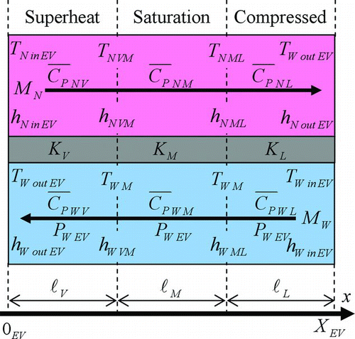
Because the number of sensors to observe the process values is limited by the complicated structure, the observed process values of the two coolants flowing inside the evaporator are temperature, pressure and mass flow rate at the inlet and outlet of the evaporator. Then, structure of the evaporator is expressed in a simplified model of countercurrent type as shown in for developing a simplified mathematical model to estimate the overall heat transfer coefficient. As shown in Figure , mass flow rate M, temperature T, pressure P, averaged specific heat under constant pressure ![]() and specific enthalpy h are used for deriving a simplified mathematical model. Provided, however, that the steam inside the evaporator is constant in pressure because the pressure loss is negligibly small, heat exchange of the vessel and the air around the evaporator is excepted from consideration. In the interior of the evaporator, the state of water changes from compressed water to saturated water vapor and turns to superheated steam by the heat of the secondary coolant of liquid sodium. The overall heat transfer coefficients differ according to the state of water. Therefore, the interior of the evaporator is divided into compressed water region, saturation region and superheat region depending on the state of water, and the overall heat transfer coefficient of each region is estimated. The temperature of saturation region, averaged specific heat under constant pressure and specific enthalpy are calculated from mass flow rate, temperature and pressure at the inlet and outlet of the evaporator.
and specific enthalpy h are used for deriving a simplified mathematical model. Provided, however, that the steam inside the evaporator is constant in pressure because the pressure loss is negligibly small, heat exchange of the vessel and the air around the evaporator is excepted from consideration. In the interior of the evaporator, the state of water changes from compressed water to saturated water vapor and turns to superheated steam by the heat of the secondary coolant of liquid sodium. The overall heat transfer coefficients differ according to the state of water. Therefore, the interior of the evaporator is divided into compressed water region, saturation region and superheat region depending on the state of water, and the overall heat transfer coefficient of each region is estimated. The temperature of saturation region, averaged specific heat under constant pressure and specific enthalpy are calculated from mass flow rate, temperature and pressure at the inlet and outlet of the evaporator.
3. Simplified mathematical models for estimating overall heat transfer coefficient
3.1. Superheater
The simplified mathematical model for estimating the overall heat transfer coefficient of the superheater K SH is derived by considering the heat balance in minute interval dx as shown in Figure . Provided, however, that the mass flow rate and pressure of liquid sodium and steam are temporally constant, and all the steam flowing into the superheater is superheated steam. The heat transfer area A SH and the temperature difference ΔT between liquid sodium and steam in dx are defined as
3.2. Evaporator
In the case of evaporator, the interior of the evaporator is divided into compressed water region, saturation region and superheat region as shown in Figure . Provided, however, that the mass flow rate and pressure of liquid sodium and water/steam are temporally constant, all water flowing into the evaporator is subcooled water, and all the steam flowing out from the evaporator is superheated steam. The overall heat transfer coefficients of compressed water region, saturation region and superheat region of the evaporator are defined as KL , KM and KV , respectively. In the same way as deriving the mathematical model for estimating the overall heat transfer coefficient of the superheater, we obtain the following mathematical models for estimating the overall heat transfer coefficients of the regions of the evaporator as shown in Equations (Equation22)–(Equation24):
It is considered that the adherence of water stain and scale to the wall of a heat transfer tube tends to occur in not superheat region but compressed water region. Then, it is assumed that the overall heat transfer coefficient of the superheat region of evaporator is calculated from that of superheater and the value of it is treated as known. Furthermore, in the saturation region of the evaporator, it is assumed that saturated vapor and saturated water have contact with the wall of the heat transfer tube in the proportion of specific volume of saturated vapor a to that of saturated water b and the overall heat transfer coefficient of the saturation region KM is given by the following equation:
where γ N SH, γ W SH, d SH and λSH are mean heat transfer coefficient between liquid sodium and wall of the heat transfer tube of superheater, heat transfer coefficient between steam and wall of the heat transfer tube of superheater, thickness and thermal conductivity of the heat transfer tube of superheater, respectively. Equation (Equation34) is transformed as the following equation:
By the assumptions, the estimated values of the overall heat transfer coefficient of superheat region vary in the same way as that of superheater. For the same reason, the estimated values of the overall heat transfer coefficient of saturation region vary in the same way as that of superheat region and compressed water region. In this study, we monitor the estimated values of the overall heat transfer coefficient of compressed water region KL for diagnosing the evaporator.
4. Estimation of overall heat transfer coefficient
4.1. Evaluation method
According to experts, it is desirable to be able to monitor 0.5% variation in the overall heat transfer coefficient for diagnosing the abnormality of the steam generator. Because the overall heat transfer coefficient stays fairly constant in a steady operation, it is considered to be able to judge a steam generator as normal if the variations, the so-called relative errors, in the estimated values of the overall heat transfer coefficient are less than ±0.5%. For confirming whether or not the relative errors in the estimated values of the overall heat transfer coefficient are less than ±0.5%, we have estimated an overall heat transfer coefficient with the mathematical models using the simulated data.
The simulated data simulates “Monju” during a steady operating test at 40% electrical power output using plant dynamics analysis code NETFLOW++ [Citation8]. The process signals of mass flow rate, inlet temperature, outlet temperature, inlet pressure and outlet pressure of the two coolants of superheater and evaporator are used for the estimations. The sampling frequency of these process signals is 1 Hz. The sensor noise and specific fluctuation of the process signals in the real observed data of “Monju” provided by the Japan Atomic Energy Agency (JAEA) are simulated by an AR (Auto-Regressive) model and added to the simulated data to conform to the real observed data. The real observed data were obtained during steady operating tests at 40% electric power output in preparation for full operation.
The relative errors of estimated values of the overall heat transfer coefficient are calculated from the following equation:
4.2. Estimation using noise filtered process values by digital filter
We have estimated the overall heat transfer coefficient using noise-filtered and time-averaged process values with a digital filter to reduce the sensor noises from the process signals and to confirm the influence of the sensor noises on the estimated values of the overall heat transfer coefficient. The digital filter is a Butterworth filter, which is one of the low-pass filters.
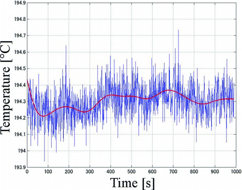
As shown in , the peak frequencies of process signals have been obtained by frequency analysis. The obtained peak frequency of a process signal is considered as not the sensor noise but the specific fluctuation of the process signal [Citation9]. Then, we set a passband edge frequency and a stopband edge frequency for each process signal to be larger than the peak frequency as shown in Table . shows examples of simulated process signal and noise-filtered process signal with Butterworth filter.
Table 1 Peak frequencies of process signals obtained by frequency analysis and setting frequencies of Butterworth filter
Figure 4 A noise-filtered process signal of temperature of liquid sodium at the inlet of evaporator; blue line is simulated process signal and red line is noise-filtered process signal
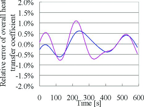
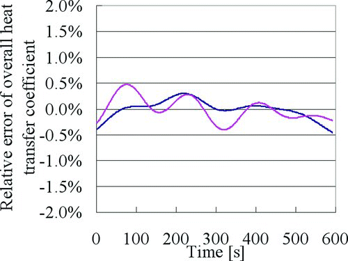
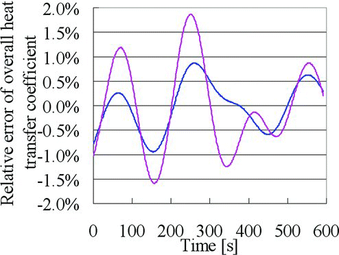
– show the estimated results of the overall heat transfer coefficient using noise-filtered and time-averaged process values per 1 minute, 2 minutes and 4 minutes, respectively. As shown in Figures and , some relative errors of estimated values of the overall heat transfer coefficient are more than ±0.5% in spite of using process signals of the steady operation. These results are thought that the noise reduction of process signals was not enough in the cases of using time-averaged process values per 1 minute and 2 minutes. The rate of relative errors of K SH and KL , which are more than ±0.5% are shown in . As the results of the estimations using time-averaged process values per 1 minute, 40% of relative errors of K SH and 66% of relative errors of KL are more than ±0.5%. As the results of the estimations using time-averaged process values per 2 minutes, 18% of relative errors of K SH and 37% of relative errors of KL are more than ±0.5%. While, as the result of the estimation using time-averaged process values per 4 minutes, all relative errors of estimated values of the overall heat transfer coefficient are less than ±0.5% as shown in Figure . The averaging time of 4 minutes is not long enough to reduce the specific fluctuation of the process signals shown in Table . Therefore, only the sensor noise can be reduced well from the process signals.
Table 2 The rate of relative errors of K SH and KL that are more than ±0.5%
Figure 5 The estimated results of the overall heat transfer coefficient using time-averaged process values per 1 minute; blue line is the relative error of K SH and pink line is the relative error of KL
5. Conclusion
In this study, a technique has been developed for diagnosing in on-line the state of the steam generator of the FBR “Monju” by estimating the overall heat transfer coefficient, which is an unobserved important state variable, from real observed data such as temperature, pressure and flow rate. The traditional inspection techniques for the wall of heat transfer tubes, such as ECT, can only carry out in a maintenance period and require a great investment of time and a wide range of processes. In addition, the sudden anomaly cannot be detected during operation by the traditional inspection techniques. Meanwhile, there is the hydrogen meter as one of the traditional techniques detecting anomalies during operation. However, the hydrogen meter cannot prevent the sodium–water reaction from occurring. The developed technique can diagnose the steam generator during operation and does not require much time and processes. Furthermore, the developed technique can prevent the sodium–water reaction from occurring because monitoring the fluctuation of estimated values of the overall heat transfer coefficient permits an indication of anomaly of the wall of heat transfer tube to be detected at an early stage. Moreover, maintenance using the developed technique together becomes safer and more efficient than only time-based maintenance because it becomes possible to grasp a decline of heat transfer efficiency with estimating and monitoring the overall heat transfer coefficient.
The structures of superheater and evaporator, which constitute the steam generator, are expressed in simple models of countercurrent type for developing mathematical models to estimate the overall heat transfer coefficient. The mathematical models of the overall heat transfer coefficient have been derived by considering the heat balance in the simple models of superheater and evaporator.
We have estimated the overall heat transfer coefficient by the mathematical models using simulated data with artificial noises. The simulated data simulates “Monju” during a steady operating test at 40% electrical power output using plant dynamics analysis code NETFLOW++. The sensor noise and specific fluctuation of the process signals in the real observed data of “Monju” provided by JAEA are simulated by an AR model and added to the simulated data to conform to the real observed data. The real observed data were obtained during steady operating tests at 40% electric power output in preparation for full operation. Therefore, noise-filtered and time-averaged process values are used to reduce the sensor noise from process signals of the simulated data. As the result of the estimations, all relative errors of the overall heat transfer coefficient of the superheater and the evaporator have been able to be estimated as less than ±0.5% that the experts require in the case of using averaged process values per 4 minutes.
In the future, we plan to confirm whether or not the developed technique can detect the occurrence of an anomaly from the simulated data with a small anomaly such as heat transfer anomaly caused by adherence of water stain of 0.1 mm to the wall of a heat transfer tube.
Nomenclature
| x | = |
Distance from inlet [m] |
| dx | = |
Minute interval of heat transfer tube [m] |
|
| = |
Averaged specific heat under constant pressure [J/kg °C] |
| M | = |
Mass flow rate [kg/s] |
| T | = |
Temperature [°C] |
| ΔT | = |
Difference in temperature between liquid sodium and water/steam [°C] |
| P | = |
Pressure [MPa] |
| h | = |
Specific enthalpy [J/kg] |
| x | = |
Length of heat transfer tube [m] |
| ℓ | = |
Length of region [m] |
| R | = |
Circumferential length of heat transfer tube [m] |
| a | = |
Heat transfer area in dx [m2] |
| A all | = |
Total heat transfer area [m2] |
| Q | = |
Total amount of heat transfer [W] |
| K | = |
Overall heat transfer coefficient [W/(m2 °C)] |
|
| = |
Averaged overall heat transfer coefficient [W/(m2 °C)] |
| R | = |
Heat transfer coefficient [W/(m2 °C)] |
| λ | = |
Thermal conductivity [W/(m °C)] |
| d | = |
Thickness of heat transfer tube [m] |
Subscripts
| N | = |
Liquid sodium |
| W | = |
Water/steam |
| SH | = |
Superheater |
| EV | = |
Evaporator |
| L | = |
Compressed water region in evaporator |
| M | = |
Saturation region in evaporator |
| V | = |
Superheat region in evaporator |
| VM | = |
Boundary between superheat region and saturation region in evaporator |
| ML | = |
Boundary between saturation region and compressed water region in evaporator |
| in | = |
Inlet |
| out | = |
Outlet |
Acknowledgements
This present study includes some of the results of “Anomaly detection agents by advanced hybrid processing of Monju process data” entrusted to Okayama University by the Ministry of Education, Culture, Sports, Science and Technology of Japan (MEXT). The authors are grateful to Japan Atomic Energy Agency for providing the observed data of Monju. The authors would like to thank Prof. Hiroyasu Mochizuki of Fukui University and Prof. Makoto Takahashi of Tohoku University for providing the simulated data of Monju with artificial noises.
References
- Onoue , A and Yamada , F. 2002 . Development of inspection technique for future commercialized FBRs , Japan : Japan Nuclear Cycle Development Institute . Japanese
- Onoue , A and Yamada , F. 2003 . Development of inspection technique for future commercialized FBRs , Japan : Japan Nuclear Cycle Development Institute . Japanese
- Onoue , A , Nishi , H , Yamada , F , Teruyama , H , Ishibashi , J , Kageyama , T and Kinjo , H. 2004 . Elemental technology development of the FBR (3) – study of inspection technique and MA incineration technique for the improvement of FBR economy . JNC Tech Rev , 24 : 107 – 118 . Japanese
- Takahashi , K , Shiina , A , Onizawa , T , Ibaki , S , Yamaguchi , T and Tagawa , A. 2009 . Inspection of the steam generator heat transfer tubes for FBR Monju restart . Proceedings of ICONE17 . Jul 12–16 2009 , Brussels , Belgium. pp. 717 – 725 . Accompanied by: Video on CD-ROM
- Technical information of Monju - auxiliary building & secondary loops - superheater Available from: http://www.jaea.go.jp/04/monju/EnglishSite/contents02-3-2.html#AB3
- Technical information of Monju - basic specification Available from: http://www.jaea.go.jp/04/monju/EnglishSite/contents02-1.html#BS7
- Technical information of Monju - auxiliary building & secondary loops - evaporator Available from: http://www.jaea.go.jp/04/monju/EnglishSite/contents02-3-2.html#AB2
- Mochizuki , H. 2010 . Development of the plant dynamics analysis code NETFLOW++ . Nucl Eng Des , 240 : 577 – 587 .
- Udagawa , K , Tomobe , K , Ueda , M and Tamayama , K. 2000 . Evaluation of fluctuation signals on steady state in Monju . JNC Tech Rev , 9 : 1 – 10 . Japanese
