Abstract
Japan sodium-cooled fast reactor (JSFR) is going to adopt an advanced fuel-handling system. From the viewpoint of spent fuel cleaning, a new dry-cleaning process instead of the conventional process with water rinse is under development. In this study, drain performance tests on the JSFR subassembly inner duct and dry-cleaning performance tests with a pin bundle model are summarized. Based on the experimental data of the inner duct and pin bundle model tests, residual sodium on the spent fuel subassembly after argon gas cleaning has been evaluated to be 400 g. Water alkalinity and purification performance have been evaluated and the JSFR water pool system has shown the capability to accept 400 g residual sodium on the spent fuel subassembly after argon gas cleaning.
1. Introduction
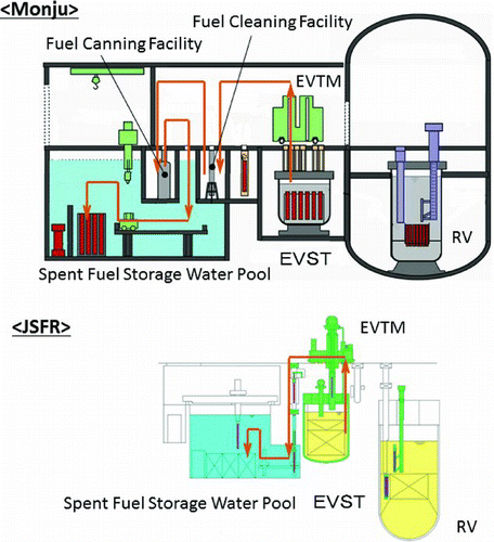
Japan sodium-cooled fast reactor (JSFR) is a commercialized fast reactor concept with 1500 MW electric output and it has challenging targets on safety, economy, and reliability [Citation1]. One of the major features of JSFR is a simplified fuel-handling system. In conventional sodium-cooled fast reactors, fuel-handling systems are rather complicated, since coolant sodium could not be exposed to the open air. The JSFR simplified fuel-handling system has been developed to enhance economic competitiveness [Citation2]. In the previous study, several innovative fuel-handling systems were compared and the present simplified system was selected regarding both safety and economic competitiveness [Citation3]. Spent fuel integrity during the transportation was preliminary evaluated during the comparative study [Citation3]. And toughness against external events was evaluated based on lessons learned from the Tokyo electric power company's Fukushima Dai-ichi nuclear power plant [Citation4]. shows the comparison between Monju and JSFR fuel-handling systems [Citation2,Citation5], from the viewpoint of spent fuel cleaning. In Monju, a spent fuel subassembly accommodated in a sodium pot is unloaded from the reactor vessel to an ex-vessel storage tank (EVST) by an ex-vessel transfer machine (EVTM). After a certain decay storage, a spent fuel subassembly is transported to a fuel-cleaning facility where sodium on the subassembly is made inert by argon gas with steam and rinsed to remove sodium products almost completely. The cleaned subassembly is canned with water at the fuel-canned facility and stored in the spent fuel storage water pool.
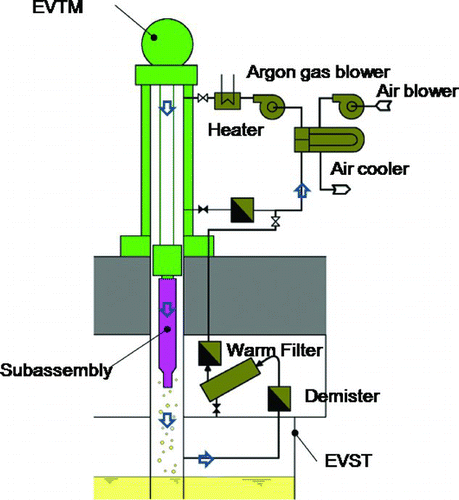
In JSFR, an advanced spent fuel cleaning process is adopted and a spent fuel subassembly is stored in the water pool directly without canning. A concept of the advanced spent fuel cleaning, so-called dry cleaning is shown in . In the dry-cleaning method, an independent facility for spent fuel cleaning like the Monju fuel-cleaning facility is not necessary. The spent fuel picked up from the EVST is held at the EVST guide tube (a tube through which the EVTM accesses to the EVST), and the argon gas circulation is provided during a certain period to blow away sodium on the spent fuel subassembly. After the gas blow, the subassembly is transported to the water pool guide tube by the EVTM. And at the guide tube, residual sodium on the spent fuel subassembly is made inert by argon gas with steam, and immersed into the water pool. Since JSFR spent fuel subassemblies are stored in the water pool without canning, a canning facility can be eliminated in JSFR. By adopting dry cleaning and spent fuel storage without canning, a certain amount of residual sodium is carried into the water pool. Water conditions of the JSFR water pool are managed by the purification system, and the sodium carried into the water pool would be accumulated at the purification system. One major feature of the new cleaning method is that the radioactive liquid waste due to spent fuel cleaning is reduced because the new process is free from spent fuel rinse, which cannot avoid a certain amount of liquid waste.
The JSFR fuel subassembly has a new feature from the viewpoint of fuel handling. It has an inner duct [Citation6] to enhance molten fuel release in case of severe accidents. The sodium drain from the inner duct is an issue, since it has only a small drain hole at the bottom. In this study, inner duct drain tests using inner duct mockups have been conducted to confirm drain performance of the inner duct. To demonstrate the proposed dry-cleaning process, a partial model of a JSFR fuel subassembly, which involves fuel pin bundle, wrapper tube, and inner duct, (pin bundle model) has been manufactured and dry-cleaning performance tests after sodium immersion have been conducted.
2. Inner duct drain test
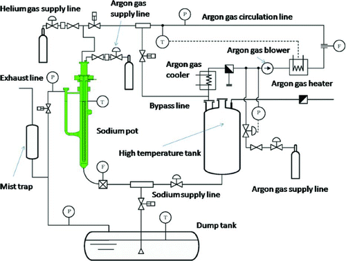
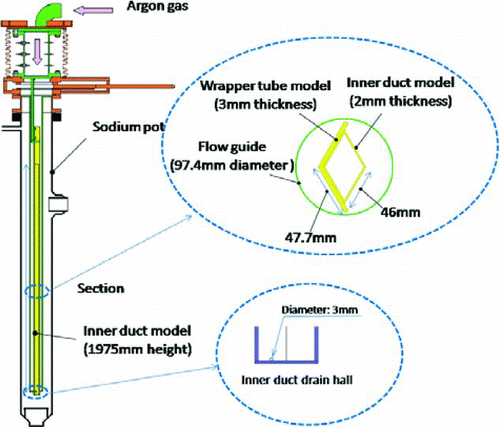
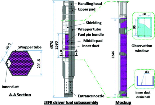
Inner duct drain tests have been conducted to confirm the performance of drain hole on the inner duct before the pin bundle test and the measurement of detail residual sodium around the inner duct including sodium on the duct bottom and the gap between the duct and wrapper tube. The experimental apparatus for the inner duct drain test is shown in . The apparatus has a sodium pot in which an inner duct model with a flow guide is accommodated. The sodium pot is connected to sodium and argon gas lines providing sodium charge/drain at the bottom of the sodium pot. A sketch of an inner duct model is shown in . The cross section of the inner duct is a rhombus with side length 46 mm and thickness 2 mm. There is a drain hole of 3 mm diameter at the bottom of the inner duct. The side length of the inner duct is full scale, while the length of the model (1975 mm) is not full scale (2690 mm) due to the sodium-pot restriction. The inner duct model is attached by a partial wrapper tube model to investigate the residual sodium between the inner duct and wrapper tube.
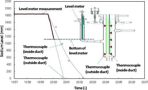
Experimental conditions and result summary are shown in . In all cases, sodium was charged into the sodium pot at 175 °C from the dump tank. Then the sodium-pot temperature was raised at 400 °C and maintained for 48 hours. Before sodium drain, the sodium temperature was lowered to 200 °C simulating EVST sodium temperature. In cases 0–1, 0–2, 0–4, and 0–5, argon gas blow was conducted simulating subassembly cleaning procedure, while other cases 0–3 and 0–6 are not followed by argon gas blow. The sodium level was monitored by a continuous sodium-level monitor and thermocouples installed inside the inner duct model as shown in . Measured sodium level of case 0–3 was also shown in as a sample case. Measured drain times of all test cases were almost the same and around 3 minutes. After the drain or drain followed by gas blow procedure, the inner duct model was pulled out from the sodium pot for residual-sodium measurement, surface observation, and disassemble, after the temperature went down to 50 °C naturally.
Table 1 Summary of inner duct drain tests
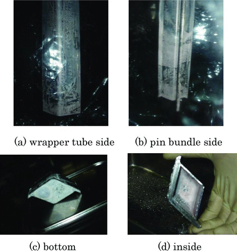
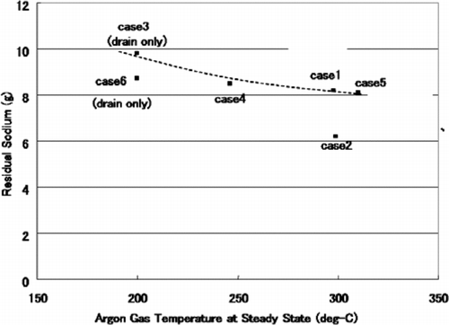
The results of the drain tests are summarized in . After the drain tests, the inner models were disassembled and the residual sodium was measured. The amounts of residual sodium are below 10 g showing sodium drains were successful in all cases. shows the photographs of the inner duct model surfaces after sodium drain in case 0–3. The residual sodium can be observed on the surfaces. The drain holes were generally observed being blockaded except for case 0–5, but those holes blockade were thought to be caused due to sodium surface tension after successful drain. Relation between argon gas temperature and residual-sodium amounts is plotted in . Though the residual sodium amount generally goes down as argon gas temperature increases, differences are not significant from the view point of drain performance.
3. Cleaning test with pin bundle model
Cleaning tests using a partial subassembly model (pin bundle model) have been conducted to demonstrate the performance of the proposed dry-cleaning methods. The experimental apparatus is the same as that of the inner duct drain tests as shown in . The schematic illustration of the pin bundle model is shown in . The section of the model is full scale of the JSFR driver fuel subassembly. The wrapper tube's outer flat–flat width and thickness are 201.6 mm and 5 mm, respectively. The number of fuel pins is 255, and an inner duct with side length of 46 mm is installed. In the previous study on demonstration fast breeder reactor (DFBR) [Citation7], spent fuel cleaning on an entire DFBR subassembly mockup was conducted. In the present study, residual sodium on the pin bundle and inner duct is focused because those design parameters are different from those of DFBR. Then the present partial model only includes fuel pin bundle area with an inner duct, and the height is 2246 mm while the JSFR fuel pin bundle is 2690 mm height.
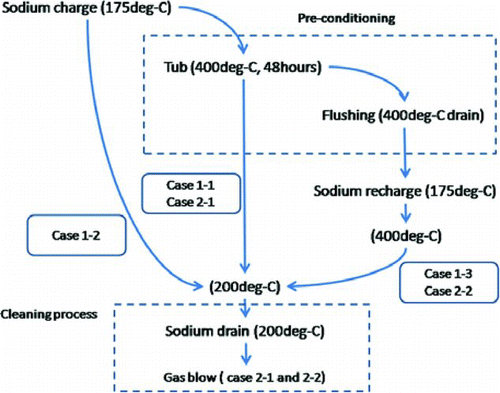
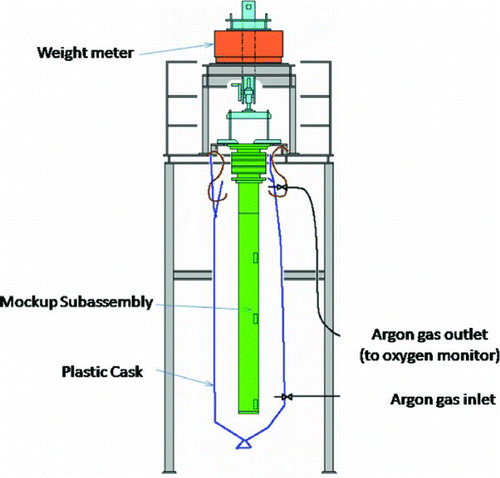
Experimental conditions are summarized in . There are five cases in total: cases 1–1 to 1–3 are without gas blow, and cases 2–1 and 2–2 are with gas blow. The temperature and duration of gas blow down are 250 °C and 20 minutes, respectively, since they do not affect significantly in the inner duct test. Other important parameters are pre-experiment process such as sodium immerse and hot drain in . The experimental procedures are shown in . In the subassembly cleaning test, the pin bundle model is reused repeatedly. Removal of residual sodium and surface condition recovery are extremely important, since those conditions really affect cleaning performance. In almost all cases except for case 1–2, the subassembly was immersed in sodium at 400 °C for 48 hours to remove residual sodium or sodium products formed due to previous test cases. In cases 1–3 and 2–2, sodium was drained at 400 °C and sodium was newly recharged for the cleaning tests. In all cases, sodium is drained at 200 °C, simulating the EVST condition. After the cleaning process, the sodium pot and the pin bundle model temperatures were decreased to discharge the pin bundle model from the sodium pot for weight measurement and surface observation. While the residual sodium was being measured, the pin bundle model was covered with a plastic cask as shown in . The plastic cask is connected to an argon gas line for continuous purge and oxygen level at the outlet of the argon gas line is monitored.
Table 2 Summary of pin bundle model cleaning test
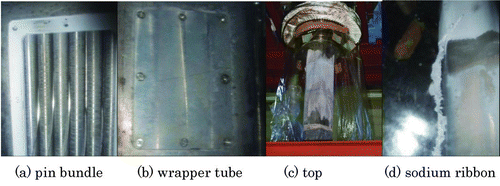
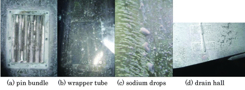
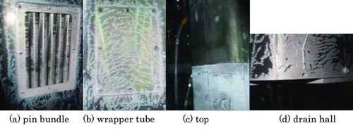
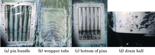
– show photographs of the pin bundle model after dry cleaning. The figures are arranged in the order of experimental cases. In case 1–1, this is the first case of all and without gas blow, there was observed thin sodium films and small drops on the pin bundle and wrapper tube surfaces as shown in and . There is observed a certain amount of residual sodium above the sodium level as shown in and a sodium ribbon is also found as shown in . The residual sodium above the sodium level is thought to be due to sodium-vapor accumulation during 400 °C sodium immersion. In later cases, inert gas purge above the sodium level is reinforced to mitigate sodium-vapor accumulation. The measured residual sodium in case 1–1 is approximately 150 g, excluding sodium ribbon and sodium-vapor accumulation above the sodium level.
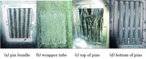
The second as shown in is case 2–1 with gas blow. Surface appearances are not far from those of case 1–1 as shown in and . Sodium-vapor accumulation above the sodium level is successfully mitigated as shown in . There is hardly observed residual sodium in the area above the sodium level. One feature of the case with gas blow is that residual sodium at the bottom of the pin bundle seems slightly thicker than those of other parts as shown in . A cause of this difference is thought to be that the gas blow moves sodium to the bottom of the pin bundle. The amount of the residual sodium is approximately 160 g.
The third is case 1–2 without gas blow. The residual-sodium amount of case 1–2 is 1280 g and this value is extremely larger than those of others. A major reason of this large amount of sodium is thought to be the surface conditions of the pin bundle model. Since case 1–2 was accompanied by neither hot draining nor 400 °C sodium immerse, there could be sodium products on the model surface, and the residual-sodium products might accumulate further sodium on the model surface. Surface sodium on the pin bundle and the wrapper tube is apparently thicker than those of other cases as shown in and . There are also observed large sodium drops as shown in . The inner duct hole is blockaded as shown in . The blockage and certain amount of sodium in the inner duct was confirmed by a wire insertion from the drain hole. The blockage is thought to be caused by the residual sodium in the inner duct. Since case 1–1 is not immersed in the sodium at 400 °C, there could be sodium products on the test model wall, which was not dissolved by sodium at 200 °C. The residual sodium products could clog the drain hole and a major amount of 1280 kg was thought to remain in the inner duct. Later cases 1–3 and 2–1 are accompanied by 400 °C sodium immerse and hot drain to recover surface conditions of the pin bundle model. In fact, the drain hole blockage was not observed in case 1–3 after case 1–2. The accumulated sodium product including the drain hole blockage is thought to be successfully dissolved by 400 °C sodium.
Case 1–3 is almost the same case as case 1–1 without gas blow. Surface appearances as shown in and are similar to those in case 1–1. There is hardly observed residual sodium above the sodium level as shown in and the drain hole seems open as shown in . The residual sodium amount is 80 g that is smaller than that in case 1–1. One reason for the sodium amount difference is thought to come from the sodium-vapor accumulation above the sodium level.
Case 2–2 is the similar case as case 2–1 with gas blow. Surface appearances are similar to those of case 2–1 as shown in –15(d). The amount of residual sodium is 190 g and is similar to that of case 2–1 of 160 g.
The amounts of residual sodium are summarized in . Dry-cleaning process is successful in almost all cases except for case 1–2. The extreme amount of the residual sodium of case 1–2 is thought to come from surface conditions affected by the previous case. Case 1–2 could be excluded from evaluation of the dry-cleaning process because JSFR spent fuel subassemblies are not going to experience gas environment exposure before discharge from the EVST. After irradiated in the core, the spent fuel subassemblies are transported inside the sodium pot to the EVST and stored under sodium in the EVST until the dry-cleaning process. Cases 1–1 and 1–3 provide drain only results. The amounts of residual sodium are 150 g and 80 g, respectively. Cases 2–1 and 2–2 provide results with drain and gas blow. The amounts of residual sodium seem a little bit larger than those of drain only cases. One reason for the difference between with and without gas blow cases could be sodium oxidation during gas blow. From the viewpoint of cleaning performance, the residual-sodium amounts of both with and without gas blow cases are thought to be small enough to be carried in the spent fuel storage pool.
4. Design evaluations
Based on the experimental results of residual-sodium density of each part of the pin bundle model, the amount of residual sodium on the JSFR subassembly was evaluated taking into account uncertainty and design margin. For the handling head, shielding, pin bundle, duct outside, and wrapper tube, residual-sodium density has been evaluated based on residual sodium on the observation windows of the pin bundle model. For the pin bundle, residual-sodium density has been evaluated based on the pin bundle model test. For the duct inside and duct-wrapper tube contact, the inner duct test data have been applied. For the entrance nozzle, residual-sodium data of the previous experiments [Citation7] have been applied since the pin bundle model does not include the entrance nozzle [Citation7]. Taking into account the uncertainty, experimental data have been analyzed statistically evaluating 90% confidence interval (CI). Case 1–2 was excluded from the statistical analysis samples, since the case 1–2 results were strongly affected by the surface conditions of the previous case. shows evaluated residual-sodium density of the JSFR subassembly. From the results, residual-sodium densities are categorized into five groups: pin bundle, side walls and special parts like the duct bottom, duct-wrapper tube contact, and entrance nozzle. On evaluation of uncertainty, t-distribution is assumed. Four cases with and without argon gas blow except for case 1–2 are assumed to be in the same population, since the differences in residual sodium are not clearly different between cases with and without argon gas blow. Evaluating the sodium density on the window plates, there are three windows on the pin bundle model and data from those windows are assumed to be in the same population. General parts without complex structures, which include handling head, shielding, outside of inner duct, and wrapper tube, are evaluated based on sodium densities on the window plates with 90% CI. For the inner duct, residual-sodium amounts on the duct bottom. For the general parts, results show that the 90% CI of the pin bundle model and inner duct tests could be covered 8 g/m2. Major parts of the inner duct are evaluated based on the measured sodium density on each part in the inner duct tests. For the gap at the inner duct bottom, it is assumed that the gap is filled with sodid sodium conservatively. For pin bundle, residual sodium on the pin bundle is assumed to be the remainder of subtraction of general parts and inner duct parts from the total residual sodium on the pin bundle model. As a result, 90% CI of residual-sodium density was evaluated to be 10.09 g/m2 and covered by 11 g/m2. For entrance nozzle, the residual-sodium density is evaluated based on the evaluation on DFBR [Citation7]. Based on the DFBR evaluation, the sodium density at the entrance nozzle including bottom of the pin bundle was evaluated to be 110 g/m2. Based on that residual-sodium density evaluation, the total residual-sodium amount on the JSFR spent fuel subassembly after dry cleaning was evaluated to be approximately 400 g.
Table 3 Evaluation of residual sodium on subassembly
In case 1–2, a drain hole blockage was thought to result from the sodium products obtained in the previous cases. In the plant operation, spent fuel subassemblies are free from those sodium products, since they are stored under sodium with impurity control after refueling. However, from the safety point of view, monitoring of successful drain or improved drain hole is necessary to secure prevention of large residual sodium in the inner duct.
From the viewpoint of the fuel-handling system design, acceptability of the evaluated residual sodium amount has been analyzed. After dry cleaning, the spent fuel subassembly is transported to the water pool guide tube and the residual sodium is inerted by humid argon gas and steam. Experiences in Joyo and Monju [Citation8–Citation11] showed that duration of the sodium inert process would depend on sodium density on spent fuel subassemblies and the inert process duration would be approximately 25 minutes. For the JSFR fuel-handling design, the inert process duration is designed to be 30 minutes conservatively based on the Joyo and Monju experiences.
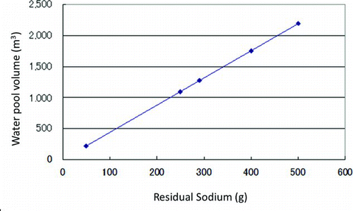
From the view points of water conditions in the water pool, alkalinity has been evaluated. The alkalinity limit of the pool water is pH less than 10 based on the corrosion experiments [Citation12]. Relation between residual sodium and required water pool volume to maintain pH under 9 is shown in . The required water pool volume for the 400 g residual sodium is evaluated to be 1600 m3. Since the JSFR water pool volume is approximately 2000 m3, the water pool has the capability to accept residual sodium of 400 g and the purification system has the capability to accept three spent fuel subassemblies per day. In the JSFR design, spent fuel subassemblies are transported from the EVST to the water pool during power operation and two subassemblies are operated in a day.
5. Conclusions
Performance of the dry-cleaning process is basically confirmed by the above experiments. The inner duct drain tests show that the 3 mm diameter drain hole could provide good drain performance in EVST sodium condition showing amounts of residual sodium below 10 g. The pin bundle cleaning tests show that the dry-cleaning performance is good enough either with or without argon gas blow. Amounts of residual sodium in all cases are below 200 g except the case in which the pre-experimental surface conditions are not well managed. Based on the experimental data of the inner duct and the pin bundle model tests, the residual sodium on the spent fuel subassembly after argon gas cleaning has been evaluated to be 400 g. Water alkalinity and purification performance have been evaluated, and the JSFR water pool system has shown capability to accept 400 g residual sodium on the spent fuel subassembly after argon gas cleaning.
Acknowledgements
The present study includes the results of “Development of fuel-handling system” entrusted to “The Japan Atomic Power Company (JAPC)” by the Ministry of Education, Culture, Sports, Science and Technology of JAPAN (MEXT).
Notes
aArgon gas blow was continued until temperature settled steady. In case 0–2, the gas blow was continued in 1 hour after the temperature had reached the steady state.
bIn cases 0–3 and 0–6, argon gas blow was not used.
aThe pin bundle model was immersed in 400 °C sodium for 48 hours before sodium draining.
bAfter 400 °C sodium immerse, the sodium was drained at 400 °C and sodium was recharged for cleaning tests. In cases 1–1 and 2–1, sodium temperature is decreased to 200 °C after immerse to start cleaning process (200 °C drain).
References
- Uto , N , Sakai , T , Mihara , T , Toda , M , Kotake , S and Aoto , K . 2009 . “ Conceptual design for Japan sodium-cooled fast reactor (1) current status for system design for JSFR ” . In Proceedings of the International Congress on Advances in Nuclear Power Plants Tokyo , , Japan
- Usui , S , Mihara , T , Obara , H and Kotake , S . 2009 . “ Development of advanced loop-type fast reactor in Japan ” . In Proceedings of the International Congress on Advances in Nuclear Power Plants Tokyo , , Japan
- Chikazawa , Y , Uzawa , M , Usui , S , Tozawa , K and Kotake , S . 2012 . Comparison of sodium-cooled reactor fuel-handling systems with and without an ex-vessel storage tank . Nucl Technol , 177 : 293 – 302 .
- Katoh , A , Chikazawa , A and Uzawa , M . 2012 . “ Evaluation and improvement on external-hazard proof of JSFR fuel handling system ” . In Proceedings of the International Congress on Advances in Nuclear Power Plants Chicago , IL
- Suzuki , F , Nagahiro , Y , Funato , H , Fujiki , K and Inoue , T . 1991 . “ Design and construction of the fuel handling and storage facility for the fast breeder reactor Monju ” . In Proceedings of the International Conference on Fast Reactors and Related Fuel Cycles Kyoto , , Japan
- Mizuno , T and Niwa , H . 2004 . Advanced MOX core design study of sodium-cooled reactor in current feasibility study on commercialized fast reactor cycle system in Japan . Nucl Technol , 146 : 155 – 163 .
- Chikazawa , Y , Hori , T , Usui , S , Aizawa , K , Konomura , M and Nishiguchi , Y . 2005 . “ Design study on a fuel handling system in a sodium cooled reactor ” . In JNC TY9400 2005–009 , Japan : Japan Nuclear Cycle Development Institute . Japanese
- Yorihisa , K and Sato , I . 1979 . “ Experimental fast reactor JOYO fundamental test– performance test of the fuel cleaning facility ” . In PNC TN941 79–41(3) , Japan : Power Reactor and Fuel Development Corporation . Japanese
- Suzuki , T , Ito , H , Ebata , K and Kuno , S . 1991 . “ Operational experience of the fuel cleaning facility in JOYO ” . In PNC TN9410 91–155 , Japan : Japan Nuclear Cycle Development Institute . Japanese
- Monju Construction Office . 1996 . “ Operation and maintenance experience on the fuel handling systems and storage facilities of MONJU (1) ” . In PNC TN2410 96–005 , Japan : Japan Nuclear Cycle Development Institute . Japanese
- Obata , H , Taniguchi , H , Iseki , A , Ohuchi , K , Matsusaka , M and Nagahiro , Y . 1992 . “ Sodium cleaning test by spent fuel cleaning system ” . In Transaction of the 1992 Fall Meeting of the Atomic Energy Society of Japan Vol. B14 , Nagoya , , Japan Japanese
- Narita , T , Ukai , S , Kaito , T , Ohtsuka , S and Matsuda , Y. 2008 . Water corrosion resistance of ODS Ferritic-Martensitic steel tubes . J Nucl Sci Technol. , 45 : 99 – 102 . doi: 10.1080/18811248.2008.9711419
