Abstract
The displacement cross-sections, implemented in the particle and heavy ion transport code system (PHITS), have been calculated to estimate the radiation damage in structural materials used at accelerator facilities. The event generator in PHITS was used to calculate displacement cross-sections for 14 elemental targets and two practical alloys irradiated with neutrons at energies from 10−10 MeV to 3 GeV, and protons and deuterons at energies from several keV to 3 GeV. These displacement cross-sections were used to estimate the displacement per atom (DPA) in the target assembly at accelerator driven system (ADS) Target Test Facility (TEF-T) using 400-MeV protons, and in the Type 316 stainless steel target using 40-MeV deuterons. For the target assembly at TEF-T using 400-MeV protons, the DPA value for the proton component was approximately twice higher than that for the neutron component. For the Type 316 target using 40-MeV deuterons, radiation damage took place near the surface of Type 316 because of the Coulomb scattering effect between the incident deuterons and the material.
1. Introduction
As the power of accelerators is increasing, design predictions of the radiation damage for the structural materials become of utmost importance. Currently, there are new material irradiation facilities in the design phase such as the accelerator driven system (ADS) Target Test Facility (TEF-T) [Citation1] at Japan Proton Accelerator Research Complex (J-PARC) and the International Fusion Materials Irradiation Facility (IFMIF) [Citation2]. The TEF-T is a material irradiation facility which can accept proton beams (whose power and energy should not exceed 250 kW and 400 MeV, respectively) into the spallation target of a lead–bismuth eutectic (LBE), in order for the material irradiation and target engineering tests to be conducted. Regarding the IFMIF, a 10 MW–40 MeV beam of deuterons is required to optimize the production of neutrons.
Displacement per atom (DPA) is widely used as an index of displacement damage intensity to evaluate the damage incurred on the structural materials by radiation. This measure is related to the number of the Frenkel pairs, which are defined as a pair of a vacancy and a self-interstitial atom in the irradiated material. These point defects affect the macroscopic material properties, such as hardness. In general, displacement damage is induced by the primary knock on atoms, the so-called PKA, which is produced by the elastic scattering of incident particles, or by residual nuclei that are produced in nuclear reactions. In addition, charged particles can directly produce PKA by Coulomb scattering. The value of DPA can be estimated from the energy and track length of these particles.
To implement the DPA calculation in materials irradiated with high-energy charged particles, we have developed a method that allows calculating the DPA values [Citation3,4] using event generator in the particle and heavy ion transport code system (PHITS) [Citation5]. The procedure for the calculation of the DPA value is as follows. (1)] The kinetic energies of PKA or secondary charged particles, including residual nuclei, are determined using intra-nuclear cascade evaporation models (INCs), INCL4.6/GEM [Citation6,7] or the Quantum Molecular Dynamics model and the evaporation and fission model (JQMD/GEM) [Citation8], in PHITS. In addition, the event generator mode for low-energy neutron irradiations [Citation9] is also used to estimate these energies. The event generator, which conserves the energy and momentum before and after a reaction, is indispensable for this calculation. (2) The damage energy [Citation10], which characterizes the displacement cascade, is then derived from these energies, considering the ratio of energy losses due to the elastic scattering of lattice atoms and the electronic excitation. (3) The displacement cross-section between PKA or the secondary charged particle and the target atom is calculated from the damage energy in each event, using the Norgertt-Robinson-Torrens (NRT) model [Citation10], which predicts only the number of initially displaced atoms produced in the cascades of atom–atom collisions, and the universal one-parameter differential Coulomb scattering cross-section [Citation11]. (4) The DPA value is estimated from the displacement cross-section multiplied by the track length of the charged particle, which is calculated from the particle transport simulation of PHITS.
However, the event-by-event analysis of PKA kinetic energy and Coulomb scattering cross-section is time consuming compared with the DPA calculation method that uses displacement cross-section database multiplied by fluences of incident particles. Therefore, the event-by-event analysis is not suitable for the efficient design of accelerator facilities. Recently, researchers at the Karlsruhe Institute of Technology (KIT) analyzed the data files that include displacement cross-sections, and this data is available for neutron and proton irradiations with energies of up to 3 GeV [Citation12]. The KIT database of displacement cross-sections is listed below:
For KIT data files, the nuclear data taken from ENDF/B-VII [Citation13] was used for the recoil spectra calculation at incident nucleon energies below several MeV, and this data was processed to calculate displacement cross-section using the nuclear data processing system NJOY code [Citation14]. At higher energies, the nuclear recoil spectra were calculated using the model that describes the INC [Citation15–17]. On the other hand, this data is not sufficient for DPA calculations in structural materials at TEF-T, which contain many elements such as C, Si, Mn, Nb, Mo, and Pb. No displacement cross-section data is available at the moment for the deuteron irradiation at IFMIF.
In the present work, we have used event generator (including the event generator mode for low-energy neutron irradiations and INCL4.6/GEM in PHITS) to develop the database of displacement cross-sections for materials that are irradiated with neutrons, protons, and deuterons. The nuclear data, JENDL-4.0 [Citation18], was used for the event generator mode for low-energy neutron irradiations. The database includes 14 elemental targets and Type 316 stainless steels and ferrite steel T91, for neutron, proton, and deuteron energies of up to 3 GeV. The elemental targets used at these facilities are common structural materials, i.e., C, Al, Si, V, Cr, Mn, Fe, Ni, Cu, Nb, Mo, W, Pb, Bi .
In addition, defect production efficiencies (the ratio of survived defects to NRT predictions) were considered for iron, copper, and tungsten, as listed in a previously published article [Citation19]. The calculated displacement cross-sections were compared with the KIT data and with the experimental results. Finally, we applied the calculated displacement cross-sections to the DPA estimations of the TEF-T target irradiated with 400 MeV–250 kW protons and of the Type 316 target irradiated with 40 MeV–10 MW deuterons. The calculated ratio of the atomic parts per million (appm) of helium and hydrogen production to the DPA value (appm/dpa) for proton irradiations is also briefly shown.
2. A method to calculate the displacement cross-section
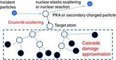
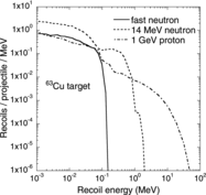
shows an overview of the method that was used to calculate the displacement cross-section [Citation3,4]. The important point is that the PKA and the secondary charged particle, which we collectively term “recoils”, generate the atomic cascade damage via Coulomb scattering. For neutron irradiations with En < 20 MeV, the recoils are created by the event generator mode in each event [Citation9,Citation20]. In the case of high-energy neutron, proton, and deuteron irradiations, the recoils are calculated by using the INCL4.6 that was developed by Boudard et al. [Citation6]. The authors improved the nuclear reaction model induced by the nucleons and by the light clusters, typically from deuterons to alpha particles, and have done this for per nucleon incident energies down to a few MeV. As a result, their model is able to produce satisfactory differential cross-sections for both incident nucleons and incident light clusters, and residue-production cross-sections for cluster-induced reactions at low energy [Citation6]. shows energy spectra of the recoil in copper that was irradiated with fast and 14-MeV neutrons using the event generator mode in PHITS and with 1-GeV protons using the INCL4.6/GEM in PHITS. The energy of fast neutrons is distributed as follows: 53% are in the 0.1 < En < 0.5 MeV range; 29% are in the 0.5 < En < 1 MeV range; and 18% are in the 1 < En < 2 MeV range. The maximal energy of the recoil in copper is about 150 keV for fast neutrons, 2 MeV for 14-MeV neutrons, and 50 MeV for 1-GeV protons, respectively. For 1-GeV protons, recoils produced by the inelastic collisions are dominant in the recoil energy spectrum above about 3 MeV.
Figure 2. The recoil energy spectra produced in copper at fast neutron, 14-MeV neutron and 1-GeV proton irradiations. For fast neutrons, the distribution of energies is 53% in the range 0.1 < En < 0.5 MeV, 29% in the range 0.5 < En < 1 MeV, and 18% in the range 1 < En < 2 MeV, respectively.
The Coulomb scattering part in is described within the classical scattering theory using the screening functions f(t1/2). A universal one-parameter differential scattering cross-section equation in reduced notation is expressed by Lindhard et al. [Citation11] as
(1) where t is a dimensionless collision parameter defined by
(2) where T is the energy that is transferred to the target, θc is the center-of-mass angle of the scattered projectile and Tmax is the maximal transferred energy, given as
(3) where M1 is the projectile mass, M2 is the target mass, and Ep is the energy of the incident charged particles and recoils. The parameter ϵ is the dimensionless energy given as
(4) In the above expression, dc is the unscreened (i.e., Coulomb) collision diameter or distance of the closest approach for a head-on collision, and aTF is the screening distance.
Lindhard et al. considered f(t1/2) to be a simple scaling function and the variable t to be a measure of the depth of penetration into the atom during a collision, with large values of t representing small distances of approach. The function f(t1/2) can be generalized to provide a one-parameter universal differential scattering cross-section equation for inter-atomic potentials such as screened and unscreened Coulomb potentials. The general form is
(5) where λ, m, and q are the fitting variables, with λ = 1.309, m = 1/3 and q = 2/3 for the Thomas–Fermi version [Citation11] of f(t1/2). The value of t1/2 increases with an increase in the dimensionless energy ϵ, the scattering angle in the center of mass (CM) system, and the impact parameter.
The scenarios of various irradiations will be described by using the “damage energy,” Tdamage, to characterize the displacement cascade. The“damage energy” is the energy that is transferred to the lattice atoms, and it is the reduction in energy due to the losses to electronic stopping in the atom-displacement cascade. This energy was given by Norgett et al. [Citation10]:
(6) where T is the energy that is transferred to a target atom, and it is given by EquationEquation (2)
(2) as
(7) where ϵp is the dimensionless projectile energy that is given by EquationEquation (4)
(4) and the projectile energy Ep. The parameters kcascade and g(ϵ) are given as
(8)
(9) The quantity ϵ is the dimensionless transferred energy that is given by EquationEquations (4)
(4) and Equation(7)
(7) . Note that this calculation does not include the self-healing of lattice defects.
To estimate the displacement cross-sections, the NRT formalism [Citation10] is employed as a standard to determine that fraction of the target atom PKA energy that will generate the damage, e.g., further nuclear displacements. The displacement cross-sections, which indicate the Coulomb scattering cross-section multiplied by the number of defects, can be evaluated from the following expression:
(10) where tmax in its dimensionless form is equal to ϵ2 from EquationEquation (2)
(2) when θc = π. The quantity td is the displacement threshold energy in dimensionless form, given by EquationEquation (4)
(4) . Displacement threshold energies, Tthreshold,that are used in the PHITS are summarized in [Citation21]. For most metals, the typical values ranged between 15 and 90 eV.
Table 1. The displacement threshold energies, Tthreshold, used in the PHITS.
The parameter NNRT is the number of defects [Citation11], and it is obtained using the Lindhard slowing-down theory for irradiated materials as
(11) The constant 0.8 in the above formula is the displacement efficiency that is given as being independent of the recoil energy, the target material, or its temperature. The value is intended to compensate for the forward scattering in the displacement cascade of the lattice atoms.
The parameter η in EquationEquation (10)(10) is the defect production efficiency (the ratio of survived defects to NRT predictions) which is based on the investigations by Stoller [Citation22] and Broeders and Konobeyev [Citation19]. These researchers summarized the analyses of the number of survived defects calculated using the molecular dynamics model (MD) and binary collision approximation (BCA). Theoretical considerations, based on the MD and BCA analyses, have shown that during the evolution of a cascade many initial vacancies and interstitials will recombine; these studies also showed that the NRT model overestimates the number of displacements. The authors therefore created the database of displacement cross-sections, in addition to the defect production efficiency for iron, copper, and tungsten, which depends on the damage energy, as shown in . The fitting curves were obtained for the MD results below 15 keV for copper and 30 keV for iron and tungsten [Citation19], and the BCA results above these energies, in the presentation by Konobeyev at the technical meeting of “Primary radiation damage from nuclear reaction to point defects” which was organized by the International Atomic Energy Agency [Citation12].
Figure 3. Defect production efficiency versus the damage energy. Curves were fitted based on the calculation with BCA and MD [Citation19].
![Figure 3. Defect production efficiency versus the damage energy. Curves were fitted based on the calculation with BCA and MD [Citation19].](/cms/asset/9eff135a-c06e-4909-a939-0aff5d346f17/tnst_a_851042_f0003_b.gif)
3. Calculation of displacement cross-section
The 14 elemental targets include displacement cross-sections without the defect production efficiency, σNRT, and three elemental targets include those with defect production efficiency, σBCA–MD. These cross-sections were calculated for the elements of materials as shown below:
σNRT: C, Al, Si, V, Cr, Mn, Fe, Ni, Cu, Nb, Mo, W, Pb, Bi
σBCA–MD: Fe, Cu, W
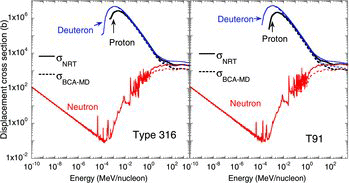
shows the comparison between the σNRT and σBCA–MD displacement cross-sections for iron irradiated with protons, neutrons, and deuterons, for energies ranging from 10−10 MeV to 3 GeV. For incident particle energies above ∼10 keV, the cross-section σBCA–MD was smaller than σNRT, due to the defect production efficiencies. For the irradiation with deuterons, the displacement cross-sections for energies higher than 20 MeV (which are mainly produced by the secondary particles) agree with the data obtained for protons and neutrons, within a factor of 1.5. shows the displacement cross-sections for Type 316 and T91 that were irradiated with neutrons, protons, and deuterons. Type 316 and T91 will be used for sample of beam window and irradiation specimen.
Figure 4. The calculated displacement cross-sections, σNRT and σBCA–MD, for iron irradiated with protons, neutrons, and deuterons.
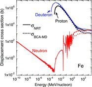
Figure 5. The displacement cross-sections, σNRT and σBCA–MD, for Type 316 and T91 irradiated with protons, neutrons, and deuterons. The cross-section σBCA–MD includes the displacement cross-section for iron only with defect production efficiency.
Sample given in atomic%:
Type 316: Fe (67.44%), Cr (18.4%), Ni (11.52%), Mo (1.47%), Mn (1.0%), C (0.19%)
T91: Fe (87.65%), Cr (9.57%), Si (0.59%), Mo (0.58%), Mn (0.50%), C (0.46%), V (0.22%), Ni (0.19%), Nb (0.05%)
The quantity σBCA–MD of Type 316 and T91 includes σBCA–MD of iron and σNRT of others. The cross-sections of T91 and Type 316 are similar to the cross-section of iron because iron is the main component of these.
shows the comparison between the σBCA–MD that was calculated using the PHITS and the data that was taken from the KIT data file that included the displacement cross-sections [Citation12] for iron and copper that were irradiated with protons and neutrons. For the irradiation with protons, the PHITS results are in a good agreement with the KIT data over a wide range of energies. For the irradiation with neutrons, the agreement between the two sets of results is also satisfactory. On the other hand, there is little difference between the results obtained for the neutrons with energies ranging from 10−3 to 10−2 MeV. It might be due to the difference in nuclear data used in the calculation of displacement cross-sections. JENDL-4.0 was used for the event generator mode in PHITS and ENDF/B-VII was used for KIT data. It may also result from different processes of nuclear elastic scattering in the event generator mode and the data processing with NJOY code. Note that the neutron resonance cross-section for the PHITS results disagrees with the KIT data because of the different meshes of neutron energy.
Figure 6. The displacement cross-sections versus incident energy of protons (black line) and neutrons (red line). Solid and dashed lines are the results that were calculated from the PHITS and KIT data [Citation12], respectively.
![Figure 6. The displacement cross-sections versus incident energy of protons (black line) and neutrons (red line). Solid and dashed lines are the results that were calculated from the PHITS and KIT data [Citation12], respectively.](/cms/asset/198d749f-7122-4dcc-aedb-5b8458c9a036/tnst_a_851042_f0006_oc.jpg)
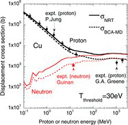
summarizes displacement cross-sections in aluminum and copper that were irradiated with fast neutrons [Citation23] and 14-MeV neutrons [Citation24], and in copper and tungsten that were irradiated with 1.1- and 1.94-GeV protons [Citation3,Citation25]. For the PHITS calculations, the cross-section σBCA–MD for aluminum was derived with the averaged ⟨η⟩ as given in [Citation19] because the equation of η with the energy dependence for aluminum was not found in the literature search [Citation19]. The experimental data of damage-resistivity rate at low temperature, around 4 K, are also shown. Conventionally, based on the measurements of the radiation-produced increase in resistivity at around 4 K to freeze the motion of interstitials, the experimental displacement cross-sections are derived using the measured increase in resistivity and the Frenkel pair resistivity, which is given by material studies [Citation19]. In general, the cross-section σNRT was larger than the experimentally obtained value by a factor of 2–3, while the cross-section σBCA–MD was in a good agreement with the experimental data, within a factor of 2. It indicates that the recombination between initial vacancies and interstitials, simulated by the BCA and MD analyses, is observed in the experiment.
shows the displacement cross-sections for protons and neutrons versus the incident energy, for energies ranging from 0.1 MeV to 3 GeV. The defect production efficiency, η, was set as 1 for the σNRT curves (solid lines), and η was included for the σBCA–MD curves (dashed lines). For protons with energies above 20 MeV, the secondary particles are more dominant than the PKA produced by the incident particles, and the contribution of the Coulomb scattering for the secondary particles increases as a function of energy. At low proton energies, there is data that was derived by Jung from the experimental electron, light ion and neutron damage rates [Citation26], and the PHITS results are in good agreement with the data. In all cases, the difference between the σBCA–MD and the σNRT increases with increasing energy. This results from the damage energy dependency on η as shown in , i.e., η decreases with damage energy related to the recoil and changes from 0.3 to 0.5. In order to validate the displacement cross-sections in the energy range from 20 MeV to 1 GeV, experimental data for this energy range is needed.
4. Application to radiation damage in materials
4.1. TEF-T target assembly
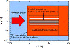
The TEF-T target, shown in , is a walled structure made of T91 with LBE flowing inside [Citation1]. Eight irradiation specimens are placed within the target filled with LBE. The specimens are made of Type 316 and T91 as candidate materials of the beam window of the ADS. The lifetime of these materials depends on the displacement damage. Therefore, it is of interest to assess the effect of the PHITS-calculated displacement cross-sections on the estimation of the radiation damage to the beam window and the specimens of the TEF-T target. For this purpose, the cross-sections are folded into calculated proton and neutron fluences in the PHITS. The 400-MeV protons collide with the beam window, and protons and neutrons affect the radiation damage at the target assembly. We assumed a Gaussian beam profile with full width at half-maximum of 3.71 cm and 4500 hours/year of operation at the beam power of 250 kW [Citation1].
Table 2. The calculated and experimental displacement cross-sections in aluminum and copper irradiated with fast neutrons [Citation23] and 14-MeV neutrons [Citation24], and in copper and tungsten irradiated with 1.1- and 1.94-GeV protons [Citation3,Citation25]. For the PHITS calculations, the cross-section σBCA–MD for aluminum was derived with the averaged ⟨η⟩ given as in [Citation19].
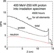
As an example of the calculated results, shows the depth dependence of the DPA value for 0.2 × 4 × 15 cm irradiation specimen irradiated by 400 MeV–250 kW proton beam with 4500 hours of irradiation time and using σNRT. The proton component of the DPA value includes the defect production from projectiles and secondary charged particles. The neutron component includes the defect production from secondary charged particles created by the neutron scatterings. In the case of 400-MeV proton beams, nuclear collisions occur before the stopping range is reached, and displacement cross-section contributions for charged particles created by protons and neutrons increase the overall DPA value at target depths. The DPA value for the proton component is approximately twice higher than that for the neutron component. The peak structure is seen at around 13.5 cm corresponding to the stopping
Table 3. The DPA values and the ratio of the atomic parts per million (appm) of helium and hydrogen production to DPA value at the top of irradiation specimen and the center of beam windows for TEF-T calculated using σNRT and σBCA–MD. The calculated data taken from the ESS report [Citation27,Citation29] at the center of a stainless steel beam window of spallation source at ESS are also listed.
length for 400-MeV protons in Type 316. On the other hand, DPA contribution for protons is clearly seen over 13.5 cm. Since the stopping length for 400-MeV proton in LBE is 1 cm longer than that in Type 316, scattered protons in LBE come into Type 316 over 13.5 cm.
Figure 9. Depth dependence of the DPA value for 0.2 × 4 × 15 cm irradiation specimen irradiated by 400 MeV–250 kW proton beam with 4500 hours of irradiation time and using σNRT.
Predicting helium and hydrogen in structural materials is also important [Citation27]. Here these values are reported without detailed discussions. Calculations of gas production in Type 316 and T91 were performed using the INCL4.6/GEM in PHITS, which results in a good agreement with the experimental results of helium production [Citation28]. lists the DPA values and the appm of helium and hydrogen production at the center of the beam window and at the top of the irradiation specimen in the TEF-T target assembly, calculated using the σNRT and σBCA–MD cross-sections. For each material, these are the ones that are most damaged by the radiation. Note that the cross-section σBCA–MD for Type 316 and T91 includes the displacement cross-section for iron only. The maximal DPA values that were obtained using the σNRT for the irradiation specimen and the beam window at TEF-T were estimated to be 13.5 and 12.1 dpa, respectively. These values obtained by σNRT are twice higher than those obtained by σBCA–MD. It is convenient to express the helium and hydrogen production and the DPA value in terms of appm/dpa [Citation27]. It should be mentioned that the radiation damage induced by spallation reactions is particularly characterized by a large He/dpa ratio in appm/dpa, compared to the value of ∼0.5 appm/dpa in fission reactor [Citation27]. To compare with other calculated results, also lists the DPA values taken from the European Spallation Source (ESS) report [Citation27,Citation29] without defect production efficiencies and appm of helium and hydrogen production at the center of a stainless steel beam window of spallation source at the ESS with 1.3 GeV–5 MW proton beam.
shows the calculated appm/dpa ratio that was obtained using the standard NRT estimation without defect production efficiencies for hydrogen and helium at the center of beam window at the TEF-T assembly. Calculated results were compared to other calculated results that were reported in the ESS report [Citation27,Citation29] and were obtained using a stainless steel irradiated with 1.3-GeV protons, and to results that were calculated by Lu et al. using an iron irradiated with 0.8, 1.0, and 2.0-GeV protons [Citation27,Citation30], respectively. Our calculated ratio for helium production with 400-MeV incident protons is an extrapolation of these reported values, and is satisfactorily consistent with them.
Figure 10. Comparisons of various data on appm/dpa ratios without defect production efficiencies as a function of the energy of incident protons (this work with a T91 beam window irradiated with 400-MeV protons, the ESS report data that was obtained by using a stainless steel irradiated with 1.3-GeV protons [Citation27,Citation29], and results that were calculated by Lu et al. using an iron irradiated with 0.8-, 1.0-, and 2.0-GeV protons [Citation27, Citation30]).
![Figure 10. Comparisons of various data on appm/dpa ratios without defect production efficiencies as a function of the energy of incident protons (this work with a T91 beam window irradiated with 400-MeV protons, the ESS report data that was obtained by using a stainless steel irradiated with 1.3-GeV protons [Citation27,Citation29], and results that were calculated by Lu et al. using an iron irradiated with 0.8-, 1.0-, and 2.0-GeV protons [Citation27, Citation30]).](/cms/asset/1bd5b44d-3654-46c6-b51b-251f0f1e6a5c/tnst_a_851042_f0010_b.gif)
4.2. DPA estimations for Type 316 irradiated with deuterons
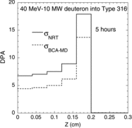
For the design of IFMIF, we considered the accidental case of a beam that projects directly onto the Type 316 beam pipe. The dimension of calculation is same as in , but a walled structure and LBE are replaced with air. shows DPA distributions in 0.2 × 4 × 15 cm Type 316 irradiated with the beam of deuterons that had the incident energy of 40 MeV and power of 10 MW [Citation2]; these distributions were obtained using the σNRT and σBCA–MD. The duration of irradiation was 5 hours. Note that the cross-section σBCA–MD for Type 316 irradiated with deuterons includes the displacement cross-section for iron only. Radiation damage takes place near the surface of Type 316, corresponding to the so-called Bragg peak, because it is dominated by the Coulomb scattering effect between the beam of incident deuterons and the material. Maximal DPA values that were obtained using the σNRT and σBCA–MD were estimated to be 17.9 and 13.7 dpa, respectively. Regarding the effect of recombination of radiation-produced defects, we should take into account that NRT prediction should be regarded as maximal values under ideal conditions with low temperature and in which there is no thermal spontaneous defect recombination [Citation27].
5. Summary
We used the event generator mode and INCL4.6/GEM in the PHITS code to calculate the displacement cross-sections for 14 elements that were irradiated with neutrons at energies ranging from 10−10 MeV to 3 GeV, and protons and deuterons at energies ranging from several keV to 3 GeV. Recoil energies were obtained using the event generator mode for neutron incidences with energies ranging from 10−10 to 20 MeV, and using INCL4.6/GEM for other particles. The number of defects was calculated with NRT model and the defect production efficiency for iron, copper, and tungsten (the ratio of survived defects, calculated based on the results of molecular dynamics and binary collisions available in the literature, to NRT predictions). We found that displacement cross-sections calculated using the event generators were in good agreement with the KIT data and the experimental results. Calculated displacement cross-sections were used to calculate the DPA values in the beam window and the irradiation specimen developing at ADS TEF-T using 400-MeV protons, and in Type 316 using 40-MeV deuterons. In the case of the target assembly at TEF-T, the DPA value for the proton component was approximately twice higher than that for the neutron component. For the Type 316 target using 40-MeV deuteron, radiation damage took place near the surface of Type 316 because of the Coulomb scattering effect between the incident deuterons and the material. We also showed the calculated ratio of the appm of helium and hydrogen production to the DPA value (appm/dpa) for proton irradiations. These results were consistent with the calculated results for the ESS target irradiated with 1.3-GeV protons and an iron irradiated with 0.8-, 1.0-, and 2.0-GeV protons. Thus, the calculated displacement cross-sections, implemented in PHITS, can be applied to estimate the DPA values in structural materials used at accelerator facilities for neutron, proton, and deuteron irradiations.
Acknowledgements
We would like to express our gratitude to Drs T. Sawai, T. Fukahori, and C. Konno of Japan Atomic Energy Agency (JAEA) for their advice on the method for calculating the displacement cross-sections.
References
- Pyeon CH, editor. Current status on research and development of accelerator-driven system and nuclear transmutation technology in Asian countries: KURRI-KR(CD)-40, ISSN 1349-7960; 2013.
- IFMIF International Team. An activity of the International Energy Agency (IEA) implementing agreement for a program of research and development on fusion materials. IFMIF comprehensive design Report; 2004.
- Iwamoto Y, Niita K, Sawai T, Ronningen RM, Baumann T. Improvement of radiation damage calculation in PHITS and tests for copper and tungsten irradiated with protons and heavy-ions over a wide energy range. Nucl Instruments Methods B. 2012;274:57–64.
- Iwamoto Y, Niita K, Sawai T, Ronningen RM, Baumann T. Displacement damage calculations in PHITS for copper irradiated with charged particles and neutrons. Nucl Instruments Methods B. 2013;303:120–124.
- Sato T, Niita K, Matsuda N, Hashimoto S, Iwamoto Y, Noda S, Ogawa T, Iwase H, Nakashima H, Fukahori T, Okumura K, Kai T, Chiba S, Furuta T, Sihver L. Particle and heavy ion transport code system PHITS, version 2.52. J Nucl Sci Technol. 2013;50:913–923.
- Boudard A, Cugnon J, David JC, Leray S, Mancusi D. New potentialities of the Liege intranuclear cascade model for reactions induced by nucleons and light charged particles. Phys Rev C. 2013;87:014606.
- Furihata S. Statistical analysis of light fragment production from medium energy proton-induced reactions. Nucl Instruments Methods B. 2000;171:251–258.
- Niita K, Chiba S, Maruyama T, Maruyama T, Takada H, Fukahori T, Nakahara Y, Iwamoto A. Analysis of the (N,Xn’) reactions by quantum molecular-dynamics plus statistical decay model. Phys Rev C. 1995;52:2620–2635.
- Niita K, Iwamoto Y, Sato T, Matsuda N, Sakamoto Y, Nakashima H, Iwase H, Shiver L. Event generator models in the particle and heavy ion transport code system: PHITS. J Korean Phys Soc. 2011;59:827–832.
- Norgett MJ, Robinson MT, Torrens IM. A proposed method of calculating displacement dose rates. Nucl Eng Des. 1975;33:50–54.
- Lindhard J, Nielsen V, Scharff M, Thomsen P. Integral equations governing radiation effects (notes on atomic collisions, III). Mat Fys Medd Dan Vid Selsk. 1963;33:1–42.
- Konobeyev AYu, Fischer U. What we can improve in the calculation of displacement cross-sections. Technical meeting of primary radiation damage from nuclear reaction to point defects. Vienna, Austria: IAEA Headquarters; 1–4 October 2012. Available from: http://www-nds.iaea.org/CRPdpa/dpa.html
- Chadwick MB, Oblozinsky P, Herman M, Greene NM, McKnight RD, Smith DL, Young PG, MacFarlane RE, Hale GM, Frankle SC, Kahler AC, Kawano T, Little RC, Madland DG, Moller P, Mosteller RD, Page PR, Talou P, Trellue H, White MC, Wilson WB, Arcilla R, Dunford CL, Mughabghab SF, Pritychenko B, Rochman D, Sonzogni AA, Lubitz CR, Trumbull TH, Weinman JP, Brown DA, Cullen DE, Heinrichs DP, McNabb DP, Derrien H, Dunn ME, Larson NM, Leal LC, Carlson AD, Block RC, Briggs JB, Cheng ET, Huria HC, Zerkle ML, Kozier KS, Courcelle A, Pronyaev V, van der Marck SC. ENDF/B-VII.0: next generation evaluated nuclear data library for nuclear science and technology. Nucl Data Sheets 2006;107:2931–3059.
- MacFarlane RE, Muir DW. The NJOY nuclear data processing system version 91. 1994; LA-12740-M.
- Konobeyev AYu, Fischer U. Advanced evaluations of displacement and gas production cross-sections for chromium, iron, and nickel up to 3 GeV incident particle energy. International Meeting on Nuclear Applications of Accelerators (AccApp’11); 2011 April 3–7; Knoxville, TN, USA.
- Broeders CHM, Konobeyev AYu. Displacement cross-sections for tantalum and tungsten irradiated with protons at energies up to 1GeV. J Nucl Mater. 2005;336:201–209.
- Broeders CHM, Konobeyev AYu, Villagrasa C. Neutron displacement cross-sections for tantalum and tungsten at energies up to 1 GeV. J Nucl Mater. 2005;342:68–76.
- Shibata K, Iwamoto O, Nakagawa T, Iwamoto N, Ichihara A, Kunieda S, Chiba S, Furutaka K, Otuka N, Ohasawa T, Murata T, Matsunobu H, Zukeran A, Kamada S, Katakura J. JENDL-4.0: a new library for nuclear science and engineering]. J Nucl Sci Technol. 2011;48:1–30.
- Broeders CM, Konobeyev AYu. Defect production efficiency in metals under neutron irradiation. J Nucl Mater. 2004;328:197–214.
- Iwamoto Y, Niita K, Sato T, Matsuda N, Iwase H, Nakashima H, Sakamoto Y. Application and validation of event generator in the PHITS code for the low-energy neutron-induced reactions. Prog Nucl Sci Technol. 2011;2:931–935.
- Fukahori T, Chiba S, Shibata K, Ikeda Y, Aruga T. Watanabe Y, Murata T, Yamano N, Kawai M. JENDL PKA/KERMA file for IFMIF project. Proceedings of the Tenth International Symposium on Reactor Dosimetry; 1999 Sept. 12–17; Osaka, Japan.
- Stoller RE. The role of cascade energy and temperature in primary defect formation in iron. J Nucl Mater. 2000;276:22–32.
- Horak JA, Blewitt TH. Isochronal recovery of fast neutron irradiated metals. J Nucl Mater. 1973/74;49:161–180.
- Guinan MW, Kinney JH, Van Konynenburg RA. Defect production and recovery in fcc metals irradiated at 4.2 K. J Nucl Mater. 1985;133–134: 357–360.
- Greene GA, Snead CL, Jr, Finfrock CC, Hanson AL, James MR, Sommer WF, Pitcher EJ, Waters LS. Direct measurements of displacement cross sections in copper and tungsten under irradiation by 1.1-GeV and 1.94-GeV protons at 4.7 K. Proceedings of Sixth International Meeting on Nuclear Applications of Accelerator Technology (AccApp’03); 2004; Ja Grange Park, Illinois, USA. p. 881–892.
- Jung P. Atomic displacement functions of cubic metals. J Nucl Matter. 1983;117:70–77.
- Filges D, Goldenbaum F. Handbook of spallation research, theory, experiments and applications. Berlin (Germany): Wiley-VCH Verlag GmbH KGaA; 2009. p. 215–232.
- Ammon K, Leya I, Lavielle B, Gilabert E, David J-C, Herpers U, Michel R. Cross sections for the production of helium, neon and argon isotopes by proton-induced reactions on iron and nickel. Nucl Instruments Methods B 2008;266:2–12.
- Bauer G, Broome T, Filges D, Jones H, Lengeler H, Letchford A, Rees G, Stechemesser H, Thomas G. The European spallation source study, Vol. III. Report ESS-96-53-M, ESS Council, 1996.
- Lu W, Wechsler MS, Dai Y. The NCSU radiation damage database: proton-induced damage energy and applications to radiation damage at SINQ. J Nucl Mater. 2006;356:280–286.

